Advertisement
Quick Start
The basic procedures required to power on CEM310/311:
(1). Require DC +4.75V~20V power at minimum 6.75A (4.75V) and 1.6A
(20V). Make sure the power is OFF before connecting the
CEM310/311.
(2). Check to ensure the onboard switch SW1 is set to default (ON (up)
position).
(3). Attach thermal solution to the CEM310/311, refer to section Installing
Thermal Solution.
(4). Install the CEM310/311 onto COM Express
CEB94008 or CEB94017 baseboard.
(5). Properly install all necessary peripheral devices such as hard disk,
display, keyboard and etc. to the baseboard.
(6). Firmly attach power supply to the baseboard power connector.
(7). Turn on the system power.
(8). Press power button on the baseboard to start CEM310/311.
4
TM
baseboard, for example,
9418D310000E
©
Copyright 2018 Axiomtek Co., Ltd.
Version A3 October 2018
Printed in Taiwan
CEM310 / CEM311 Quick Installation Guide
Checklist
CEM310/311 Board x1
Quick Installation Guide x1
Note: Please contact your local vendors if any damaged or missing items. DO
NOT apply power to the board if there is any damaged component.
Please refer to the product information DVD for the complete user's
manual, drivers and utilities. User's manual and related documents are
in Acrobat PDF format.
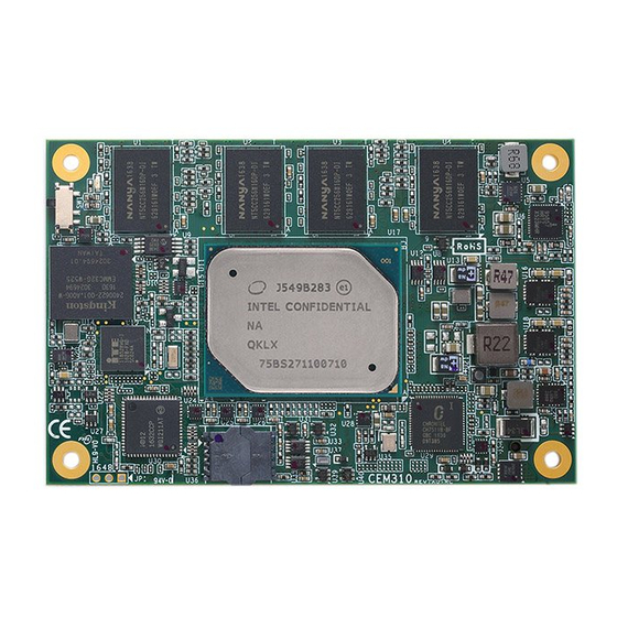
Module Layout
T
op View
9418D310000E
©
Copyright 2018 Axiomtek Co., Ltd.
Version A3 October 2018
Printed in Taiwan
Product Information DVD x1
1
Advertisement
Table of Contents

Related Manuals for AXIOMTEK CEM310


Summary of Contents for AXIOMTEK CEM310
- Page 1 (2). Check to ensure the onboard switch SW1 is set to default (ON (up) position). Note: Please contact your local vendors if any damaged or missing items. DO (3). Attach thermal solution to the CEM310/311, refer to section Installing NOT apply power to the board if there is any damaged component. Thermal Solution.
- Page 2 All heat generating components are thermally conducted to the heatspreader in order to avoid hot spots. Below images illustrate how to install the thermal solution on CEM310/311. 1. There is a protective plastic covering on the thermal pads. This must be removed before the heatspreader can be mounted.
Need help?
Do you have a question about the CEM310 and is the answer not in the manual?
Questions and answers