
Related Manuals for AXIOMTEK CEM313


Summary of Contents for AXIOMTEK CEM313
- Page 1 CEM312/313 ® Intel Atom E3950/E3940/E3930, ® ® Pentium N4200 and Celeron N3350 COM Express Type 6 Compact Module User’s Manual...
-
Page 2: Disclaimers
Axiomtek does not make any commitment to update the information in this manual. Axiomtek reserves the right to change or revise this document and/or product at any time without notice. No part of this document may be reproduced, stored in a retrieval system, or transmitted, in any form or by any means, electronic, mechanical, photocopying, recording, or otherwise, without the prior written permission of Axiomtek Co., Ltd. -
Page 3: Esd Precautions
Wear a wrist-grounding strap, available from most electronic component stores, when handling modules and components. Trademarks Acknowledgments Axiomtek is a trademark of Axiomtek Co., Ltd. ® Windows is a trademark of Microsoft Corporation. AMI is a trademark of American Megatrend Inc. -
Page 4: Table Of Contents
Table of Contents Disclaimers ..................... ii ESD Precautions ................... iii Chapter 1 Introduction ..........1 Features ....................1 Specifications ..................2 Utilities Supported ................3 Chapter 2 Module and Pin Assignments ....5 Module Dimensions and Fixing Holes ..........5 Module Layout .................. - Page 5 Appendix A Watchdog Timer and GPIO ....57 About Watchdog Timer ..............57 How to Use Watchdog Timer ............57 About GPIO ..................57 Sample Program ................58 Appendix B BIOS Flash Utility ........ 59...
- Page 6 This page is intentionally left blank.
-
Page 7: Chapter 1 Introduction
Introduction ® The CEM312 is a new COM Express Type 6 Compact Module supporting Intel Atom quad core x7-E3950, x5-E3940 and dual core x5-E3930. Meanwhile, CEM313 is a new COM ® ® ® Express Type 6 Compact Module supporting Intel... -
Page 8: Specifications
1.60GHz. ® - Intel Atom quad core x5-E3940 1.60GHz. ® - Intel Atom dual core x5-E3930 1.30GHz. CEM313 ® ® - Intel Pentium quad core N4200 1.10GHz. ® ® - Intel Celeron dual core N3350 1.10GHz. -
Page 9: Utilities Supported
CEM312/313 COM Express Type 6 Compact Module Power Management ACPI (Advanced Configuration and Power Interface). Form Factor Compact module 95mm x 95mm. Utilities Supported Chipset driver Graphics driver Ethernet utility and driver Trusted execution engine ... - Page 10 CEM312/313 COM Express Type 6 Compact Module This page is intentionally left blank. Introduction...
-
Page 11: Module And Pin Assignments
CEM312/313 COM Express Type 6 Compact Module Chapter 2 Module and Pin Assignments Module Dimensions and Fixing Holes Top View Module and Pin Assignments... - Page 12 CEM312/313 COM Express Type 6 Compact Module Bottom View Module and Pin Assignments...
-
Page 13: Module Layout
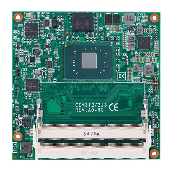
CEM312/313 COM Express Type 6 Compact Module Module Layout Top View Module and Pin Assignments... - Page 14 CEM312/313 COM Express Type 6 Compact Module Bottom View Module and Pin Assignments...
-
Page 15: Installing Thermal Solution
CEM312/313 COM Express Type 6 Compact Module Installing Thermal Solution For thermal dissipation, a thermal solution enables the CEM312/313’s components to dissipate heat efficiently. All heat generating components are thermally conducted to the heatsink in order to avoid hot spots. Figure below illustrates how to install the thermal solution on CEM312/313. - Page 16 CEM312/313 COM Express Type 6 Compact Module When installing CEM312/313 on CEB94006 or CEB94011, please add stand-off and secure with nut. Then, use the screws to secure heatsink plate to CEM312/313. Note Module and Pin Assignments...
-
Page 17: Switch Settings
CEM312/313 COM Express Type 6 Compact Module Switch Settings Properly configure switch settings on the CEM312/313 to meet your application purpose. Below you can find a summary table of all switches and onboard default settings. Once the default switch setting needs to be changed, please do it under power-off condition. -
Page 18: Connectors
CEM312/313 COM Express Type 6 Compact Module Connectors Signals go to the other parts of the system through connectors. Loose or improper connection might cause problems, please make sure all connectors are properly and firmly connected. Here is a summary table which shows connectors on the hardware. Connector Description SODIMM1... - Page 19 CEM312/313 COM Express Type 6 Compact Module Signal Signal Signal Signal GND (FIXED) GND (FIXED) GND (FIXED) GND (FIXED) GBE0_MDI3- GBE0_ACT# GBE0_MDI3+ LPC_FRAME# USB_SSRX0- USB_SSTX0- GBE0_LINK100# LPC_AD0 USB_SSRX0+ USB_SSTX0+ GBE0_LINK1000# LPC_AD1 GBE0_MDI2- LPC_AD2 USB_SSRX1- USB_SSTX1- GBE0_MDI2+ LPC_AD3 USB_SSRX1+ USB_SSTX1+ GBE0_LINK# N.C.
- Page 20 CEM312/313 COM Express Type 6 Compact Module Signal Signal Signal Signal N.C. N.C. N.C. N.C. GPO2 N.C. TYPE2# PCIE_TX3+ PCIE_RX3+ N.C. N.C. PCIE_TX3- PCIE_RX3- N.C. N.C. GND (FIXED) GND (FIXED) GND (FIXED) GND (FIXED) PCIE_TX2+ PCIE_RX2+ N.C. N.C. PCIE_TX2- PCIE_RX2- N.C.
-
Page 21: Chapter 3 Hardware Description
CEM312/313 COM Express Type 6 Compact Module Chapter 3 Hardware Description Microprocessor ® ® The CEM312/313 supports Intel Atom x7-E3930, x5-E3940/E3950 and Pentium N4200 ® ® and Celeron N3350 processors which enable your system to operate under Windows and Linux environments. The system performance depends on the microprocessor. You must install the thermal solution or cooler carefully and properly to prevent damage. -
Page 22: I/O Port Address Map
CEM312/313 COM Express Type 6 Compact Module I/O Port Address Map ® ® ® The Intel Pentium /Celeron N4200/N3350 and Atom E3930/E3940/E3950 processors communicate via I/O ports. The I/O port addresses are available for assigning to other devices via I/O expansion cards. ®... -
Page 23: Interrupt Controller (Irq) Map
CEM312/313 COM Express Type 6 Compact Module Interrupt Controller (IRQ) Map ® The interrupt controller (IRQ) mapping list (with CEB94006 baseboard under Windows 10) is shown as follows: Hardware Description... - Page 24 CEM312/313 COM Express Type 6 Compact Module Hardware Description...
- Page 25 CEM312/313 COM Express Type 6 Compact Module Hardware Description...
- Page 26 CEM312/313 COM Express Type 6 Compact Module Hardware Description...
- Page 27 CEM312/313 COM Express Type 6 Compact Module Hardware Description...
- Page 28 CEM312/313 COM Express Type 6 Compact Module Hardware Description...
- Page 29 CEM312/313 COM Express Type 6 Compact Module Hardware Description...
- Page 30 CEM312/313 COM Express Type 6 Compact Module Hardware Description...
- Page 31 CEM312/313 COM Express Type 6 Compact Module Hardware Description...
-
Page 32: Memory Map
CEM312/313 COM Express Type 6 Compact Module Memory Map ® The memory (with CEB94006 baseboard under Windows 10) mapping list is shown as follows: Hardware Description... -
Page 33: Ami Bios Setup Utility
CEM312/313 COM Express Type 6 Compact Module Chapter 4 AMI BIOS Setup Utility The AMI UEFI BIOS provides users with a built-in setup program to modify basic system configuration. All configured parameters are stored in a flash chip to save the setup information whenever the power is turned off. - Page 34 CEM312/313 COM Express Type 6 Compact Module Hot Keys Description Left/Right The Left and Right <Arrow> keys allow you to select a setup screen. The Up and Down <Arrow> keys allow you to select a setup screen or Up/Down sub-screen.
-
Page 35: Main Menu
CEM312/313 COM Express Type 6 Compact Module Main Menu When you first enter the setup utility, you will enter the Main setup screen. You can always return to the Main setup screen by selecting the Main tab. System Time/Date can be set up as described below. -
Page 36: Advanced Menu
CEM312/313 COM Express Type 6 Compact Module Advanced Menu The Advanced menu also allows users to set configuration of the CPU and other system devices. You can select any of the items in the left frame of the screen to go to the sub menus: ►... - Page 37 CEM312/313 COM Express Type 6 Compact Module Serial Port Configuration You can use this screen to select options for the Serial Port Configuration, and change the value of the selected option. A description of the selected item appears on the right side of the screen.
- Page 38 CEM312/313 COM Express Type 6 Compact Module Serial Port 1 (UART1) Serial Port Enable or disable serial port 1. The optimal setting for base I/O address is 248h and for interrupt request line is IRQ7. Serial Port 2 (UART2) Serial Port Enable or disable serial port 2.
- Page 39 CEM312/313 COM Express Type 6 Compact Module Hardware Monitor This screen is for fan speed control and hardware health status monitoring. This screen displays the temperature of system and CPU, fan speed in RPM and system voltages (VBAT, +3.3V, +3.3VSB and +5VSB). Smart Fan Mode Select Set Smart Fan mode.
- Page 40 CEM312/313 COM Express Type 6 Compact Module ACPI Settings You can use this screen to select options for the ACPI configuration, and change the value of the selected option. A description of the selected item appears on the right side of the screen.
- Page 41 CEM312/313 COM Express Type 6 Compact Module Trusted Computing You can use this screen for TPM (Trusted Platform Module) configuration. It also shows current TPM status information. Security Device Support Enable or disable BIOS support for security device. The default is Disabled. Once the Security Device Support is enabled, you will see the following screen.
- Page 42 CEM312/313 COM Express Type 6 Compact Module CPU Configuration This screen shows the CPU Configuration, and you can change the value of the selected option. Intel Virtualization Technology Enable or disable Intel Virtualization Technology. When enabled, a VMM (Virtual Machine Mode) can utilize the additional hardware capabilities.
- Page 43 CEM312/313 COM Express Type 6 Compact Module SATA Configuration In the SATA Configuration menu, you can see the currently installed hardware in the SATA ports. During system boot up, the BIOS automatically detects the presence of SATA devices. Chipset SATA Enable or disable SATA controller.
- Page 44 CEM312/313 COM Express Type 6 Compact Module USB Configuration USB Devices Display all detected USB devices. Mass Storage Devices Mass storage device emulation type. Auto option enumerates devices according to their media format. Optical drives are emulated as CDROM, drives with no media will be emulated according to a drive type.
- Page 45 CEM312/313 COM Express Type 6 Compact Module Serial Port Console Redirection You can use this screen to select options for Serial Port Console Redirection, and change the value of the selected option. A description of the selected item appears on the right side of the screen.
- Page 46 CEM312/313 COM Express Type 6 Compact Module Console Redirection Settings AMI BIOS Setup Utility...
- Page 47 CEM312/313 COM Express Type 6 Compact Module Utility Configuration BIOS Flash Utility BIOS flash utility configuration. For more detailed information, please refer to Appendix B. Device Configuration A description of selected item appears on the right side of the screen. For items marked with “”, please press <Enter>...
- Page 48 CEM312/313 COM Express Type 6 Compact Module Onboard DIO Configuration A description of selected item appears on the right side of the screen. For items marked with “”, please press <Enter> for more options. AMI BIOS Setup Utility...
- Page 49 CEM312/313 COM Express Type 6 Compact Module DIO Modification Enable or disable digital I/O modification. The default is Disabled. DIO port 1-8 Select this option to open DIO status sub screen. AMI BIOS Setup Utility...
- Page 50 CEM312/313 COM Express Type 6 Compact Module If DIO Modification is disabled, you are not allowed to change input/output setting. The DIO status sub screen is as follows: If DIO Modification is enabled, you can load manufacture default and access to the DIO status sub screen to change input/output setting, see image below.
-
Page 51: Chipset Menu
CEM312/313 COM Express Type 6 Compact Module Chipset Menu The Chipset menu allows users to change the advanced chipset settings. You can select any of the items in the left frame of the screen to go to the sub menus: ►... - Page 52 CEM312/313 COM Express Type 6 Compact Module North Bridge This screen shows system memory information and allows users to configure parameters of North Bridge chipset. LCD Control This item allows you to select LCD panel control options. Please press <Enter> to go to the sub menus.
- Page 53 CEM312/313 COM Express Type 6 Compact Module DDI0 Signal Select Select the DDI0 signal output to DisplayPort or HDMI/DVI. DDI1 Signal Select Select the DDI1 signal output to DisplayPort or HDMI/DVI. LVDS Panel Type Select LVDS panel resolution for the display device by selecting the appropriate setup item.
- Page 54 CEM312/313 COM Express Type 6 Compact Module South Bridge This screen allows users to configure parameters of South Bridge chipset. Wake on Lan Enable or disable integrated LAN to wake the system. AMI BIOS Setup Utility...
-
Page 55: Security Menu
CEM312/313 COM Express Type 6 Compact Module Security Menu The Security menu allows users to change the security settings for the system. Setup Administrator Password Set setup administrator password. User Password Set user password. AMI BIOS Setup Utility... -
Page 56: Boot Menu
CEM312/313 COM Express Type 6 Compact Module Boot Menu The Boot menu allows users to change boot options of the system. Setup Prompt Timeout Number of seconds to wait for setup activation key. 65535(0xFFFF) means indefinite waiting. Bootup NumLock State Use this item to select the power-on state for the keyboard NumLock. - Page 57 CEM312/313 COM Express Type 6 Compact Module Boot Mode Use this item for boot mode settings. UEFI Boot: Select support to boot any UEFI-capable OS. Legacy Boot: Select support to boot non UEFI-capable OS that expects a legacy BIOS interface.
- Page 58 CEM312/313 COM Express Type 6 Compact Module Note that the Primary IGFX Boot Display option appears only if Legacy Mode is selected, see images below. Primary IGFX Boot Display Select the video device which will be activated during POST (Power-On Self Test). The default is Auto.
- Page 59 CEM312/313 COM Express Type 6 Compact Module Backlight Control Use this item to select backlight control mode. AMI BIOS Setup Utility...
-
Page 60: Save & Exit Menu
CEM312/313 COM Express Type 6 Compact Module Save & Exit Menu The Save & Exit menu allows users to load your system configuration with optimal or fail-safe default values. Save Changes and Exit When you have completed the system configuration changes, select this option to leave Setup and continue to boot to operating system. - Page 61 CEM312/313 COM Express Type 6 Compact Module Discard Changes Select this option to quit Setup without making any permanent changes to the system configuration. Select Discard Changes from the Save & Exit menu and press <Enter>. Select Yes to discard changes. ...
- Page 62 CEM312/313 COM Express Type 6 Compact Module This page is intentionally left blank. AMI BIOS Setup Utility...
-
Page 63: Appendix A Watchdog Timer And Gpio
CEM312/313 COM Express Type 6 Compact Module Appendix A Watchdog Timer and GPIO B.1 About Watchdog Timer Software stability is major issue in most application. Some embedded systems are not watched by human for 24 hours. It is usually too slow to wait for someone to reboot when computer hangs. -
Page 64: Sample Program
CEM312/313 COM Express Type 6 Compact Module B.4 Sample Program Assembly sample code : dx,fa18 ; Set DIO 0-7 to Output al,00 dx,al dx,fa19 ; Set DIO 4-7 to High al,f0 dx,al dx,fa18 ; Set DIO 0-7 to Input al,ff dx,al dx,fa19 ;... -
Page 65: Appendix Bbios Flash Utility
Please read and follow the instructions below carefully. In your USB flash drive, create a new folder and name it “Axiomtek”, see figure below. Copy BIOS ROM file (e.g. CEM312X.005) to “Axiomtek” folder. - Page 66 Select the USB drive containing BIOS ROM file you want to update using the <> or <> key. Then press <Enter> to get into “Axiomtek” folder. Now you can see the BIOS ROM file on the screen, press <Enter> to select.
- Page 67 CEM312/313 COM Express Type 6 Compact Module Please wait while BIOS completes the entire flash update process: erase data, write new data and verify data. 10. When you see the following figure, press <Enter> to finish the update process. After that the system will shut down and restart immediately.
Need help?
Do you have a question about the CEM313 and is the answer not in the manual?
Questions and answers