AXIOMTEK CEM130 User Manual
Amd ryzen embedded v1000 processor com express type 6 compact module
Hide thumbs
Also See for CEM130:
- Quick installation manual (2 pages) ,
- Quick installation manual (2 pages)

Related Manuals for AXIOMTEK CEM130


Summary of Contents for AXIOMTEK CEM130
- Page 1 CEM130 AMD Ryzen Embedded V1000 Processor COM Express Type 6 Compact Module User’s Manual...
-
Page 2: Disclaimers
Axiomtek does not make any commitment to update the information in this manual. Axiomtek reserves the right to change or revise this document and/or product at any time without notice. No part of this document may be reproduced, stored in a retrieval system, or transmitted, in any form or by any means, electronic, mechanical, photocopying, recording, or otherwise, without the prior written permission of Axiomtek Co., Ltd. -
Page 3: Esd Precautions
Wear a wrist-grounding strap, available from most electronic component stores, when handling modules and components. Trademarks Acknowledgments Axiomtek is a trademark of Axiomtek Co., Ltd. ® Windows is a trademark of Microsoft Corporation. AMI is a trademark of American Megatrend Inc. -
Page 4: Table Of Contents
Table of Contents Disclaimers ..................... ii ESD Precautions ................... iii Chapter 1 Introduction ..........1 Features ....................1 Specifications ..................2 Utilities Supported ................3 Block Diagram ..................4 Chapter 2 Module and Pin Assignments ....5 Module Dimensions and Fixing Holes ..........5 Module Layout .................. - Page 5 Boot Menu ..................46 Save & Exit Menu ................47 Appendix A Watchdog Timer and GPIO ....49 About Watchdog Timer ..............49 How to Use Watchdog Timer ............49 About GPIO ..................49 Sample Program ................50...
- Page 6 This page is intentionally left blank.
-
Page 7: Chapter 1 Introduction
DDR-2400/3200 SO-DIMM up to 32GB and also provides maximum up to 7 lanes of PCI-Express, Gigabit Ethernet, HD audio interface, LVDS LCD and 2 configurable DDI for more flexible digital display options. The CEM130 also supports wide voltage input for various applications. -
Page 8: Specifications
CEM130 COM Express Type 6 Compact Module Specifications V1202B / 2.3GHz (12-25W). V1605B / 2.0GHz (12-25W). V1756B / 3.25GHz (35-54W). V1807B / 3.35GHz (35-54W). BIOS American Megatrends Inc. BIOS. UEFI Legacy Free. -
Page 9: Utilities Supported
CEM130 COM Express Type 6 Compact Module Power Management ACPI (Advanced Configuration and Power Interface). Operating Temperature Range -20°C to +60°C (-4°F to +140°F). Form Factor Compact module 95mm x 95mm. Utilities Supported ... -
Page 10: Block Diagram
CEM130 COM Express Type 6 Compact Module Block Diagram Introduction... -
Page 11: Module And Pin Assignments
CEM130 COM Express Type 6 Compact Module Chapter 2 Module and Pin Assignments Module Dimensions and Fixing Holes Top View Module and Pin Assignments... - Page 12 CEM130 COM Express Type 6 Compact Module Bottom View Side View Module and Pin Assignments...
-
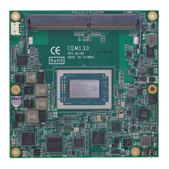
Page 13: Module Layout
CEM130 module, please be reminded that maximum height of SO-DIMM socket placed on bottom side of CEM130 is 4.0mm. With SO-DIMM module installed, maximum height from module to CEM130 PCB bottom side would be 4.8mm. - Page 14 CEM130 COM Express Type 6 Compact Module Bottom View Module and Pin Assignments...
-
Page 15: Installing Thermal Solution
Before installing the heatsink to the CPU module, please apply thermal grease on the CPU die. This CPU module has assembly holes for installing heatsink plate. Use the appropriate screws to secure the heatsink plate to the CEM130. Be careful not to over-tighten the screws. - Page 16 CEM130 COM Express Type 6 Compact Module When installing CEM130 on CEB94011, please add stand-off and secure with nut. se the screws to secure the heatsink plate to the CEM130 Then, u Note Standoff Module and Pin Assignments...
-
Page 17: Switch Settings
Type 6 Compact Module Switch Settings Properly configure switch settings on the CEM130 to meet your application purpose. Below you can find a summary table of all switches and onboard default settings. Once the default switch setting needs to be changed, please do it under power-off condition. -
Page 18: Connectors
CEM130 COM Express Type 6 Compact Module Connectors Signals go to the other parts of the system through connectors. Loose or improper connection might cause problems, please make sure all connectors are properly and firmly connected. Here is a summary table which shows connectors on the hardware. - Page 19 CEM130 COM Express Type 6 Compact Module Signal Signal Signal Signal GND (FIXED) GND (FIXED) GND (FIXED) GND (FIXED) GBE0_MDI3- GBE0_ACT# GND (FIXED) GND (FIXED) LPC_FRAME#/ GBE0_MDI3+ USB_SSRX0- USB_SSTX0- ESPI_CS0# LPC_AD0/ GBE0_LINK100# USB_SSRX0+ USB_SSTX0+ ESPI_IO_0 LPC_AD1/ GBE0_LINK1000# GND (FIXED) GND (FIXED)
- Page 20 CEM130 COM Express Type 6 Compact Module Signal Signal Signal Signal LPC_SERIRQ/ CB_RESET# DDI3_PAIR3- DDI2_PAIR3- ESPI_CS1# GND (FIXED) GND (FIXED) GND (FIXED) GND (FIXED) PCIE_TX5+ PCIE_RX5+ PEG_RX0+ PEG_TX0+ PCIE_TX5- PCIE_RX5- PEG_RX0- PEG_TX0- GPI0 GPO1 TYPE0# PEG_LANE_RV# PCIE_TX4+ PCIE_RX4+ PEG_RX1+ PEG_TX1+...
- Page 21 CEM130 COM Express Type 6 Compact Module Signal Signal Signal Signal A105 VCC_12V B105 VCC_12V C105 VCC_12V D105 VCC_12V A106 VCC_12V B106 VCC_12V C106 VCC_12V D106 VCC_12V A107 VCC_12V B107 VCC_12V C107 VCC_12V D107 VCC_12V A108 VCC_12V B108 VCC_12V C108...
- Page 22 CEM130 COM Express Type 6 Compact Module This page is intentionally left blank. Module and Pin Assignments...
-
Page 23: Chapter 3 Hardware Description
You must install the thermal solution or cooler carefully and properly to prevent damage. BIOS The CEM130 uses AMI Plug and Play BIOS with a single 64Mbit SPI Flash. System Memory The CEM130 supports two 260-pin DDR4 SO-DIMM sockets for maximum memory capacity up to 32GB. -
Page 24: I/O Port Address Map
CEM130 COM Express Type 6 Compact Module I/O Port Address Map The I/O port addresses are as follows: Hardware Description... -
Page 25: Interrupt Controller (Irq) Map
CEM130 COM Express Type 6 Compact Module Interrupt Controller (IRQ) Map The interrupt controller (IRQ) mapping list is shown as follows: Hardware Description... - Page 26 CEM130 COM Express Type 6 Compact Module Hardware Description...
- Page 27 CEM130 COM Express Type 6 Compact Module Hardware Description...
- Page 28 CEM130 COM Express Type 6 Compact Module Hardware Description...
- Page 29 CEM130 COM Express Type 6 Compact Module Hardware Description...
-
Page 30: Memory Map
CEM130 COM Express Type 6 Compact Module Memory Map The memory mapping list is shown as follows: Hardware Description... -
Page 31: Ami Bios Setup Utility
CEM130 COM Express Type 6 Compact Module Chapter 4 AMI BIOS Setup Utility The AMI UEFI BIOS provides users with a built-in setup program to modify basic system configuration. All configured parameters are stored in a flash chip to save the setup information whenever the power is turned off. - Page 32 CEM130 COM Express Type 6 Compact Module Hot Keys Description Left/Right The Left and Right <Arrow> keys allow you to select a setup screen. The Up and Down <Arrow> keys allow you to select a setup screen or Up/Down sub-screen.
-
Page 33: Main Menu
CEM130 COM Express Type 6 Compact Module Main Menu When you first enter the setup utility, you will enter the Main setup screen. You can always return to the Main setup screen by selecting the Main tab. System Time/Date can be set up as described below. -
Page 34: Advanced Menu
CEM130 COM Express Type 6 Compact Module Advanced Menu The Advanced menu also allows users to set configuration of the CPU and other system devices. You can select any of the items in the left frame of the screen to go to the sub menus: ►... - Page 35 CEM130 COM Express Type 6 Compact Module EC DIO Configuration You can use this screen to select options for Digital I/O (DIO) Configuration. A description of selected item appears on the right side of the screen. For items marked with “”, please press <Enter>...
- Page 36 CEM130 COM Express Type 6 Compact Module If DIO Modification is enabled, you can load manufacture default and access to the DIO status sub screen to change inputs/outputs setting, see images below. AMI BIOS Setup Utility...
- Page 37 CEM130 COM Express Type 6 Compact Module Serial Port Configuration You can use this screen to select options for the Serial Port Configuration, and change the value of the selected option. A description of the selected item appears on the right side of the screen.
- Page 38 CEM130 COM Express Type 6 Compact Module Serial Port 1 (UART1) Serial Port Enable or disable serial port 1. The optimal setting for base I/O address is 248h and for interrupt request line is IRQ11. Serial Port 2 (UART2) Serial Port Enable or disable serial port 2.
- Page 39 CEM130 COM Express Type 6 Compact Module Hardware Monitor This screen is for fan speed control and hardware health status monitoring. This screen displays the temperature of system and CPU, fan speed in RPM and system voltages (VBAT, +3.3V, +3.3V standby and +5V).
- Page 40 CEM130 COM Express Type 6 Compact Module ACPI Settings You can use this screen to select options for the ACPI configuration, and change the value of the selected option. A description of the selected item appears on the right side of the screen.
- Page 41 CEM130 COM Express Type 6 Compact Module Trusted Computing You can use this screen for TPM (Trusted Platform Module) configuration. It also shows current TPM status information. Security Device Support Enable or disable BIOS support for security device. AMI BIOS Setup Utility...
- Page 42 CEM130 COM Express Type 6 Compact Module CPU Configuration This screen shows CPU Configuration, and you can change the value of the selected option. SVM Mode Enable or disable SVM (Secure Virtual Machine) mode. Once enabled, you will be able to install a virtual machine on your system.
- Page 43 CEM130 COM Express Type 6 Compact Module SATA Configuration In the SATA Configuration menu, you can see the currently installed hardware in the SATA ports. During system boot up, the BIOS automatically detects the presence of SATA devices. ...
- Page 44 CEM130 COM Express Type 6 Compact Module Serial Port Console Redirection You can use this screen to select options for Serial Port Console Redirection, and change the value of the selected option. A description of the selected item appears on the right side of the screen.
- Page 45 CEM130 COM Express Type 6 Compact Module Console Redirection Settings AMI BIOS Setup Utility...
-
Page 46: Chipset Menu
CEM130 COM Express Type 6 Compact Module Chipset Menu The Chipset menu allows users to change the advanced chipset settings. You can select any of the items in the left frame of the screen to go to the sub menus: ►... - Page 47 CEM130 COM Express Type 6 Compact Module North Bridge This screen displays system memory information. And it also allows users to configure parameters of North Bridge chipset. Graphics Configuration Open sub menu for parameters related to graphics configuration. AMI BIOS Setup Utility...
- Page 48 CEM130 COM Express Type 6 Compact Module Graphics Configuration Primary Video Adaptor Select Integrated Graphics (IGD) or External Graphics (PEG). IGD UMA Frame Size Set Integrated Graphics (IGD) UMA Frame Buffer Size, see image below DDI1 Signal Select Select the DDI1 signal output to DisplayPort or HDMI.
- Page 49 CEM130 COM Express Type 6 Compact Module DDI3 Signal Select Select the DDI3 signal output to DisplayPort or HDMI. LVDS Panel Device Enable or disable LVDS panel support. Once enabled, you will be able to go further for LVDS Panel Type setting.
- Page 50 CEM130 COM Express Type 6 Compact Module South Bridge This screen shows the AMD Reference Code Version information. AMI BIOS Setup Utility...
-
Page 51: Security Menu
CEM130 COM Express Type 6 Compact Module Security Menu The Security menu allows users to change the security settings for the system. Administrator Password Set administrator password. User Password Set user password. AMI BIOS Setup Utility... -
Page 52: Boot Menu
CEM130 COM Express Type 6 Compact Module Boot Menu The Boot menu allows users to change boot options of the system. Setup Prompt Timeout Number of seconds to wait for setup activation key. 65535(0xFFFF) means indefinite waiting. Bootup NumLock State Use this item to select the power-on state for the keyboard NumLock. -
Page 53: Save & Exit Menu
CEM130 COM Express Type 6 Compact Module Save & Exit Menu The Save & Exit menu allows users to load your system configuration with optimal or fail-safe default values. Save Changes and Exit When you have completed the system configuration changes, select this option to leave Setup and continue to boot to operating system. - Page 54 CEM130 COM Express Type 6 Compact Module Discard Changes Select this option to quit Setup without making any permanent changes to the system configuration. Select Discard Changes from the Save & Exit menu and press <Enter>. Select Yes to discard changes.
-
Page 55: Appendix A Watchdog Timer And Gpio
CEM130 COM Express Type 6 Compact Module Appendix A Watchdog Timer and GPIO A.1 About Watchdog Timer Software stability is major issue in most application. Some embedded systems are not watched by human for 24 hours. It is usually too slow to wait for someone to reboot when computer hangs. -
Page 56: Sample Program
CEM130 COM Express Type 6 Compact Module A.4 Sample Program Assembly sample code : dx,fa31 ; Set DIO 0-7 to Output al,00 dx,al dx,fa32 ; Set DIO 4-7 to High al,f0 dx,al dx,fa31 ; Set DIO 0-7 to Input al,ff...
Need help?
Do you have a question about the CEM130 and is the answer not in the manual?
Questions and answers