
Related Manuals for Harvest TEC 720


Summary of Contents for Harvest TEC 720
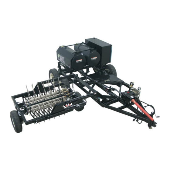
- Page 1 Owner’s Manual Model 720 Dew Simulator Natural Dew Simulation Machine Forage Harvester Model 720 Dew Simulator Owner’s Manual -18 5/18...
- Page 2 (intentionally blank)
-
Page 3: Table Of Contents
Model 720 Dew Simulator Table of Contents Page Introduction Requirements Safety Safety Decal Definitions Safety Decal Locations Setup 8-12 Unloading the Machine Connecting the Reel Connecting Hoses Connecting Perimeter Nozzle Hoses Preparing the Water Supply Trailer Hooking up Tractor, Dew Sim & Trailer Tank... - Page 4 Maintenance Schedule Preventative Maintenance Maintenance Details Heater Coil Descaling Procedure Winterizing Procedures Troubleshooting 33-36 Pin Outs 36-41 Parts Breakdown 42-59 Tine Assembly Valve Assembly Valve Exploded View Valve Trip Assembly Cross Tube Assembly Trip Assembly Cam Mount Assembly Reel Dumbbell Assembly X-Tube Bearing Assembly Perimeter Nozzle Pump Assembly Perimeter Nozzle Pump Feed...
-
Page 5: Introduction
Introduction The new Model 720 Dew Simulator allows for the precise addition of hot water mist to windrowed alfalfa. The windrow will be as soft as if it had just received the ideal amount of dew. By spraying into the windrow prior to baling, moisture is added to all of the plant material. -
Page 6: Safety
Keep your Dew Simulator in proper working condition. Unauthorized modifications to the system may impair the function and/or safety of the machine. Carefully read and understand all of the safety signs before installing or servicing the 720 Dew Simulator. Safety Decal Definitions... -
Page 7: Safety Decal Locations
Safety Decal Locations... -
Page 8: Setup
Setup Unloading the machine 1. Unload the reel skid assembly and the cart assembly shown below and remove packaging. The reel skid is designed to be handled from the front side (valves to right side) with pallet forks. Reel Skid Assembly Cart Assembly 2. -
Page 9: Connecting The Reel
Connecting the Reel 1. Position the reel skid assembly next to the cart assembly and lower the lift arm partial with the hydraulics and position the reel so it is aligned, *side with valves goes towards the cart (below left). Reel &... -
Page 10: Connecting Hoses
Connecting Hoses Lower the reel from the transport position to the field operating position so both reel tires are on the ground. Connect the stainless steel 3/4” water line attached to the back of the lift arm to the elbow attached to the swivel (below). -
Page 11: Preparing The Water Supply Trailer
Preparing the Water Supply Trailer The 720 Dew Simulator will require a water supply trailer (not included). The following step will explain the installation of the supply, return fittings and hoses. 1. Install the 2” bulkhead (connector in the bottom of the tank. Then install the 2” elbow (003-EL2020) fitting in the bulk head. -
Page 12: Hooking Up Tractor, Dew Sim & Trailer Tank
Hooking up Tractor, Dew Sim, and Trailer Tank 1. Connect the tractor to the cart assembly with a 1-1/4” draw pin (below). 2. Adjust the front hitch position to level the cart assembly to the tractor drawbar. The cleats can be moved up or down as needed. -
Page 13: Machine Setup
Machine Setup Installing Tines & Tips The reel assembly is shipped with 65 tines installed each with a size MW11 tip (below left). There are 20 plugs installed on the reel assembly as well that can be removed by using a 3/8” Allen wrench and replaced with additional tines &... -
Page 14: Tip Rate Chart - Mw5 & Mw11 Tips
(# of trips active) conditions. If tips need to be changed, a 7/16” wrench or socket will be required to remove the tip currently installed. MW5 and MW11 tips, as well as additional tines, can be purchased as spare parts from Harvest Tec. -
Page 15: Drive Chain
Drive Chain The Model 720 Dew Simulator comes with a drive chain installed, which allows the reel to be ground driven at a rate where rotation of the reel matched forward movement. This gearing allows the tines to enter and exit the windrow without significant disturbance or movement of the windrowed material. -
Page 16: Trip Sections
Trip Sections The trip sections shown (left) will determine when each cross tube section will spray as the reel assembly rotates. Trip active Trip inactive Adjusting Trip Sections Adjust trip sections that are active based on windrow size/shape/and condition. If the windrow is tall and fluffy, adjust the sections so the tines turn on as soon as they enter the windrow. -
Page 17: Operating Perimeter Nozzles
Adjusting Trip Sections (continued) Reverse View Reel Trip Section Front View Reel Trip Section Adjustment Bolts -Loosen and raise in slot, tighten to activate section -Loosen and slide down in slot to deactivate section Operation of Perimeter Nozzles The perimeter nozzles are used to apply ambient temperature (non-heated) water in a course spray as a supplement to the heated reel spray when evaporative conditions are high, either due to extremely low humidity or the presence of wind. -
Page 18: Perimeter Nozzle Gpm
Perimeter Nozzle GPM XR11008VS XR11008VS (x2) (x4) 0.80 1.60 0.98 1.96 1.13 2.26 1.26 2.53 1.39 2.77 1.50 2.99 1.60 3.20 1.70 3.39 1.79 3.58 Description of Electric Valves and Sensors 2Way Valve The 2way valve is located on the pressurized side of the pump outlet at the rear of the pump. -
Page 19: Arm Switch
Arm Switch Located towards the front of the machine on the right side of the lift arm (shown below). This is a mechanical switch that senses when the reel lift arm is in the field operating position. The arm switch is active when it senses the lift arm. -
Page 20: Installing Controls
Installing Controls 1. Attach power harness (006-7718) to tractor battery and route to the area of the drawbar. 2. Connect red wire (006-4580M) to 12VDC+ keyed source in cab and ground and run to tractor draw bar. 3. Connect power harness to connectors on cart harness (006-7720). 4. -
Page 21: Initial Operation
Initial Operation Turning on the Dew Simulator The Dew Simulator controller will turn on with the key in the tractor. In order for the controller to turn on, it must be connected to the cart harness. Priming the system 1. Initial priming of the system should be done with the heaters turned off. Ensure Heater 1 and Heater 2 are in the off position. -
Page 22: Setting Pressures
Determining Operation Settings (continued) Based on the inputted values in the field, moisture, and machine setup settings, the Target GPM and SET PRESSURE values will be calculated. **Depending upon the number of tines installed (somewhat a function of windrow width) and the Target GPM, reference the tip charts to confirm that your tip size is correct. If you tend to operate at lower GPM’s (<9GPM), it may be beneficial to run the MW5 tips. -
Page 23: Control Box
Operating (continued) While operating, ensure that the gauge pressure that you set remains close to the Set Pressure value (calculated by the control). You can also observe your target vs actual GPM on the lower right side of the main screen of the controller. -
Page 24: Field Setup Screen Steps
Field Setup Screen Steps 1. Input the estimated Tons/Acre expected to be produced in the field by pressing Ton/Acre. When selecting any of the input tabs the screen shown on right will appear to input your information. Pressing Enter will save the information. 2. -
Page 25: Main Screen
Main Screen: Tab Descriptions 1. Heater #1: Used to turn on the heater located on the left of the Dew Simulator (closest to diesel tank). o PTO must be running, flow meter must have reading, flow switch must sense flow, and arm switch or arm override must be active for heater to turn ON 2. -
Page 26: Arm Override
Heater #1 Prior to turning on heaters lift reel assembly 12” above the ground. Turn on Heater #1 by pressing the OFF button. ON will display and appear in Blue when Heater #1 is active Heater is firing when the indicator light back on the heater is illuminated ... -
Page 27: Warming Valve
Arm Override (continued) **For system priming and diagnostics, the arm switch can be overridden by the “ARM OVERRIDE” button on the controller. Activating that button will cause the 2way valve to close and allow flow to go through the heaters regardless of the lift arm position. -
Page 28: Target Psi
Target PSI (Display) Once the setup screen has had the information inputted the Target PSI will display. After the PSI info is displayed, go to the Dew Simulator and adjust the PSI regulation valve (shown right). *Tractor PTO needs to be at operating speed for this. Target GPM / Actual GPM (Display) Once the setup screen has had the information inputted the Target Gallons per Minute (GPM) will display. -
Page 29: Removal Of The Ground Drive Chain
Disconnect the coupler and connect to the fill source. Harvest Tec recommends that you have an inline screen on your fill source. Open the ball valve and begin filling. When filling is completed, shut off the fill source and close the 2" ball valve. -
Page 30: Using Surfactant
Using Surfactant The Harvest Tec 720 Dew Simulator is designed to add moisture to windrowed hay and works best with a surfactant added to the water. The surfactant will improve coverage and speed the absorption rate. While some Feed Grade surfactants will work with the Dew Simulator, Harvest Tec has tested and recommends Schaeffer Oil WET-SOL 233. -
Page 31: Heater Coil Descaling Procedure
Before you begin -- There are different types of coil cleaning chemicals. It is recommended you contact Harvest Tec for the supply of the descaling kit, descaling chemicals, and instructions for use of these chemicals. In the event that this is not possible, the instructions below should be closely followed: 1. -
Page 32: Winterizing Procedures
NOTE: Failure to properly winterize your machine may result in serious and costly damage to wetted components (pump, heater coils, reel components) of your Model 720 dew simulator if your machine is exposed to freezing temperatures. Outlined is the recommended method for all occasions during freezing weather, including long-term storage. -
Page 33: Troubleshooting
Troubleshooting 1. Pump runs, but no flow or pressure at reel. Possible Cause Solution 1a. Water supply is turned off. 1a. Turn water supply on. 1b. 2 way valve is open 1b. Reel is in transport position or reel is suspended above the ground, Arm Switch is not activated. - Page 34 Troubleshooting (continued) 4. Operating pressure excessive < 1250 PSI Possible Cause Solution 4a. Restricted discharge nozzle or plumbing 4a. Clean/Replace nozzles or components 4b. Pressure relief valve set to high, or PTO speed too high 4b. Reduce pressure setting, reduce PTO speed 4c.
- Page 35 9b. Do not change the size of the blower fan or remove the altered. increment rings from the static disc on the burner gun assembly. If the fuming condition is too excessive and cannot be removed by air band adjustment, contact Harvest Tec. NOTE: delayed ignition will also create excessive fumes.
-
Page 36: Pin Outs
Troubleshooting (continued) 10. Excessive temperature of discharge water. Possible Cause Solution 10a. T_in or T_out temperature sensors not 10a. If either temperature sensor is not functioning properly, working properly, system not receiving proper replace feedback 10b. Water pump delivery volume has decreased. 10b. - Page 37 Heater Harness 006-720E Connection H1 Pin 1 H1 12V+ Pin 2 Black H1 Gnd Pin 3 Not Used Connection H2 Pin 1 H2 12V+ Pin 2 Black H2 Gnd Pin 3 Not Used Heater Wiring 006-720F Pin 1 H 12V+ Pin 2 Black H Gnd...
- Page 38 Control to Drawbar Harness 006-7722 Pin 1 Yellow / White Flow Meter Sig Pin 2 Orange Key 12V+ Pin 3 White Arm Override 12V+ Pin 4 Green H1R1- Pin 5 Yellow H2R2- Pin 6 Blue 457R+ Arm – Sig+ Pin 7 Green / White Pin 8 Gray...
- Page 39 Dew Simulator Cart Harness 006-7720 B-Cab Controller Connector Pin 1 Yellow / White Flow Meter Sig Pin 2 Orange Key 12V+ White Arm Override Pin 3 12V+ Pin 4 Green H1R1- Pin 5 Yellow H2R2- Pin 6 Blue 457R+ Arm – Sig+ Pin 7 Green / White Pin 8...
- Page 40 Dew Simulator Cart Harness 006-7720 F- 4210 Pump 1/4" MQC Purple 4210_12V+ 1/4" FQC Black 4210_Gnd Dew Simulator Cart Harness 006-7720 G- Warmup Valve 12V+ Black Bat Gnd White Sig+ Dew Simulator Cart Harness 006-7720 H – Heater Power Bat 12V+ Black Bat Gnd Dew Simulator Cart Harness 006-7720...
- Page 41 Dew Simulator Cart Harness 006-7720 J- T_Out Sensor Pin 1 12V+ Pin 2 Not Used Pin 3 Blue/ White Tin_Sig+ Pin 4 Not Used Dew Simulator Cart Harness 006-7720 K- T_in Sensor Pin 1 Key +12V Pin 2 Bat +12V Pin 3 Not Used Pin 4...
-
Page 42: Parts Breakdown
Parts Breakdown Tine Assembly Ref Description Part # Tine Assembly 001-7202 Tip for Tines (MW11) 004-7125 Tips of Tines (MW5) 004-7123 Valve Assembly Ref Description Part # Description Part # Elbow 1/4" x 1/4” 003-DS1414EL Valve Assembly 001-7204 3 3/4” Brass Standoff Valve Hose 8”... -
Page 43: Valve Exploded View
Valve Assembly Exploded View Ref Description Part # Valve Block 001-7204VD Valve Ball 001-7104VF Valve Spring 001-7104VG Spring Retainer 001-7104VH Quad Ring 001-7104VL Plunger Pin 001-7104VE Valve Plate 001-7204VB Valve Screws 001-7204VK Roller Bracket 001-7104VA Roller 001-7204VI Roller Pin 001-7204VJ Stop Pin 001-7204VC Stop Pin Nut... -
Page 44: Cross Tube Assembly
Cross Tube Assembly 9-Tine Cross Tube Assembly (x5) 8-Tine Cross Tube Assembly (x5) Ref Description Part # Description Part # X-Tube Bearing Holder 001-7243A X-Tube Bearing Insert 001-7243B 8-Tine X-Tube 001-7207 9-Tine X-Tube 001-7206 1 1/2” Cam Bearing Plastic Bearing Washer 008-4527 008-7121 1 1/2"... -
Page 45: Cam Mount Assembly
Cam Mount Assembly Description Part # Description Part # 5/8”-11 Flange Bolt Cam Side Bracket 001-7209 Hardware 5/8”-11 Flange Nut Cam Track Back Plate 001-7203A Hardware Cam Track Outside Ring 001-7203B Idler Sprocket 001-7125 5/8”-11 x 3” Bolt Cam Track Inner Ring 001-7203C Hardware 9/16”... -
Page 46: X-Tube Bearing Assembly
X-Tube Bearing Assembly Description Part # Description Part # X-Tube Holder 001-7243A 1/4"-20 1/2" Bolt Hardware X-Tube Insert 001-7243B 1/4"-Lock Washer Hardware 3/8”-16 1 1/4" Bolt 3/8”-16 Flange Nut Hardware Hardware Perimeter Nozzle Pump Assembly Description Part # Description Part # Pump Bracket 001-7224A 3/4"... -
Page 47: Perimeter Nozzle Pump Feed
Perimeter Nozzle Pump Feed Description Part # 1” x 1” HD 003-A100100HP 1” Tee 003-TT100HP 1” x 3/4" Elbow 003-EL10034HP 1” PVC Suction Tubing 002-9005 Perimeter Nozzle Assembly Description Part # Description Part # Nozzle Bracket 001-7227 Tip Strainer 004-1203-100 1/4"... -
Page 48: Reel Assembly
Reel Assembly Description Part # Description Part # Key 3/8” x 3/8” x 1 1/2" Reel Frame Assembly 001-7218 001-7124D 1 1/2” Drive Sprocket 001-7124C Rim - 4 Bolt 008-7130 1 1/2" Bearing Bolt 008-7137 Rim Bolts for 4 Bolt 008-7130B Drive Wheel Shaft 001-7241... -
Page 49: Lift Arm Assembly
Lift Arm Assembly Description Part # Description Part # Reel Pin 1 1/4" x 4 7/8” 001-7216A 1 1/4" Thrust Bushing 008-7146B Manifold Assembly – Refer to Parts Brkdn Lift Arm Assembly 001-7211 Cart Pin 1 ¼” x 5 3/4" 3/8”... -
Page 50: Perimeter Nozzle Manifold Assembly
Perimeter Nozzle Manifold Assembly Description Part # Description Part # 4” Gauge 002-2208Z 1/2" Street Elbow 003-SE12HP Backing Plate 001-7225 1/2" Nipple 003-M1212HP Valve Manifold Brkt 001-7228 1/2" Ball Valve 002-2212 1/2” x 3/4" BH Fitting 003-A1234HP 1/2" Elbow 003-EL1212HP 1/4"... -
Page 51: Limit Switch Assembly
Limit Switch Assembly Description Part # Limit Switch Lift Arm 006-7200LS Limit Switch Bracket 001-7221 3/8”-16 Flange Nut Hardware 3/8”-16 Bolt Hardware Nozzle Backing Plate 001-7225 Pump Assembly – Need updated drawing Description Part # Description Part # Pump 1540E 007-7227 Driveline Key 001-7227B... -
Page 52: Cart Assembly
Cart Assembly 12 13 Description Part # Description Part # Cart Frame Assembly 001-7220 Tire 008-7240 Pump Assembly 001-7227 Cart Rim 008-7231 PTO Shield 001-7248 Rear Filter Brkt Asm Clevis Assembly 001-7219 Dump Valve Assm Limit Switch Assembly 001-7223 Flow Sensor Assm Pump Assm -Refer to Parts Breakdown Flange Bolt Hardware... -
Page 53: Flow Switch Assembly
Flow Switch Assembly Description Part # Description Part # 3/4" x 1/2” Reduc 3/4" x 3/4" Elbow (90) 003-DSSE34 003-DSRB3412 3/4" Tee 003-DSTT34 Temp Probes 006-4732 3/4" x 1/2" Nipple 003-DSM3412 1/2" x 3/4" Elbow (45) 003-DSEL1234S Flow Switch 006-4731 Pump Discharge Front Description Part #... -
Page 54: Pump Discharge Rear
Pump Discharge Rear Description Part # Description Part # Unloader Valve 002-7133 3/4" Tee 003-DSBT34 1/2" Socket Plug 003-DSP12 1/2" x 3/4" Elbow 003-EL1234HP 3/4" x 1/2" Fitting 003-DSM3412 1/2" Ball Valve 002-2203DV 3/4" x 3/4" Elbow (90 deg) 003-DSSE34 Unloader Valve Knob 002-7135L –... -
Page 55: Hi Temp Dump Valve Assembly
HI Temp Dump Valve Assembly Description Part # Description Part # HI Temp Valve Bkt 001-7224C 3/4" Tee 003-DSTT34 Valve Clamp Bkt 001-7224D 3/4" x 3/4" Nipple 003-DSM3434 3/4" x 3/4” Swivel 3/4" Heater Hose 002-9719 003-DSM3434S 1/2" x 3/4" Fitting 003-DSEL1234 3/4"... -
Page 56: Heater Skid Assembly - Front View
Heater Skid Assembly – Front View Description Part # Description Part # Heater Skid 001-7213 Heat Shield Bracket 001-7215B 3/8” x 3/8 Elbow Skid Clamp 001-7214 003-EL3838BF Diesel Tank 001-7212 Fuel Sight Hose 002-9709 Heater Assembly 007-7200 HS Rear Bracket 001-7215C Heat Shield 001-7215A... -
Page 57: Heater Skid Assembly - Rear View
Heater Skid Assembly – Rear View Description Part # Description Part # Filter Bracket Assem. – Refer to Pts Brkdn 3/8” Tee 003-TT38BF Flow Switch Assem. – Refer to Pts Brkdn Fuel Hose 1/4" ID 002-9711 Warmup Valve Assem. – Refer to Pts Brkdn Fuel Hose 3/8”... -
Page 58: Burner Motor Replacement Parts
Burner Motor Replacement Parts Description Part # Description Part # Burner Igniter 007-7203 Tip (optional) 007-7207-4.5 Fuel Pump 007-7204 Complete Burner Assembly 007-7201 Nozzle Assembly 007-7206 Tip (Standard) 007-7207-4.0 Burner Shut Off Valve 007-7205 Fuel Filter 007-7208 Burner Motor 007-7202... -
Page 59: Trailer Parts
Trailer Parts Description Part # Description Part # 2” Valve 3/4" Cam Socket 002-2204E 002-2220 2” x 2” Fitting 3/4" Cam Plug 002-2204B 003-A2020 2” Hose Clamp 3/4" Brass Valve 002-2200B 003-9006 3/4” Heater Hose 2” x 2” Elbow 002-9719 003-EL2020 2”... -
Page 60: Notes
Notes... - Page 61 Notes...
- Page 62 Harvest Tec, Inc. within 30 days of the failure. If it is determined that a non-Harvest Tec branded hay preservative has been used inside the Harvest Tec applicator system where the failure occurred, then Harvest Tec reserves the right to deny the warranty request at their discretion.
- Page 63 HARVEST TEC, INC. P.O. BOX 63 2821 HARVEY STREET HUDSON, WI 54016 USA PHONE: 715-386-9100 FAX: 715-381-1792 Email: info@harvesttec.com...
Need help?
Do you have a question about the 720 and is the answer not in the manual?
Questions and answers