Table of Contents
Advertisement
Quick Links
Download this manual
See also:
Operating Manual
Advertisement
Table of Contents

Related Manuals for Harvest TEC 600SS


Summary of Contents for Harvest TEC 600SS
- Page 1 Installation Manual Model 600SS Moisture Sensor Kit for Small Square Balers Forage Harvester 600SS-16-INST-BLE 5/18...
- Page 2 Council of 17 May 2006 and other applicable European Directives including Directive 2004/108/EC on the Electromagnetic compatability. The application of preservatives for hay Harvest Tec system will be turned on after being installed on a farm press has been declard in conformity with the Machinery Directive.
-
Page 3: Table Of Contents
600SS Installation Manual Table of Contents Page Introduction System Requirements Tools Needed Installation of the Moisture Sensor Installation of Dual Channel Processor Installation of the Star Wheel and Bale Rate Sensors Two-Tie Balers Three-Tie Balers Installation of End of Bale Sensor... -
Page 4: Introduction
Monitoring System has been designed to be operated through an Apple iPad (not included) using the Hay App. As well as the option to plug directly into most tractors that have an ISOBUS Monitor. The 600SS Moisture Monitoring System offers these advantages by operating through an Apple iPad: 1. -
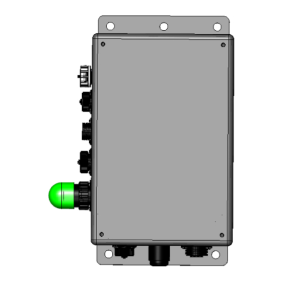
Page 5: Installation Of Dual Channel Processor
Installation of the Dual Channel Processor Follow the instructions below to mount the Dual Channel Processor (DCP) on to your specific baler model and type. The locations shown are examples of mounting the DCP on the twine box (looking at the back of the baler). -
Page 6: Installation Of The Star Wheel And Bale Rate Sensors
Installation of the Star Wheels & Bale Rate Sensors Two-Tie Balers The pair of star wheels will need to mount on the bottom side as close to the front of the bale chute as possible and at least 3/8" away from any metal. They will need to maintain a safe distance away from the twine. The star wheels will require two holes to be drilled per block, when drilling make sure to keep the wheel square to the bale chamber. -
Page 7: Three-Tie Balers
Installation of the Star Wheels & Bale Rate Sensors (continued) Three-Tie Balers The pair of star wheels will need to mount on the top as close to the knotters as possible and at least 3/8" away from any metal. They will need to maintain a safe distance away from the twine. The star wheels will require two holes to be drilled per block, when drilling make sure to keep the wheel square to the bale chamber. -
Page 8: Installation Of End Of Bale Sensor
Installation of End of Bale Sensor The end of bale sensor determines the position of the needles on the baler. When the needles cycle, the sensor communicates this information to the Dual Channel Processor. This information is used for job records and will be used by the optional Bale Identification system. -
Page 9: Installation Of The Stroke Counter Sensor
Installation of Stroke Counter Sensor The stroke counter sensor determines how many plunger strokes were used to make a bale. This sensor works in combination with the end of bale sensor and sends the information to the DCP. The information will be saved in your Job Records and will also be displayed on the screen in Automatic or Manual mode. - Page 10 Installation of Stroke Counter Sensor (continued) AGCO, New Idea, Massey Ferguson Open the left access panel as shown in Figure 9. The end of the sensor (A) will be aligned with the bolt head (B). With the tractor turned off and the PTO disconnected from the tractor, rotate the balers flywheel so that the bolt head (B) is at it lowest position.
-
Page 11: Bluetooth Receiver
Installation of Stroke Counter Sensor (continued) New Holland 200, 300 Series, 565 and BC5050 John Deere, Welger Balers, Freeman Locate the gathering fork area shown below on the baler (Figure 11). The area is shown standing at the front of the baler and looking to the back. -
Page 12: Wiring Diagram
Wiring Diagram A. Locate the tractor power/communication harness (006-6650TM(E)). B. Connect the red power wire with the 50 amp fuse to the positive side of the battery (12 volt). a. The power harness must be connected to the battery! The unit will draw more amps than convenience outlets can handle. -
Page 13: Pin Outs
Pin Outs Power/Comm Harness 006-6650TM(E) at Hitch Pin 1 Red +12V Power to TSD Pin 2 Red +12V Power to DCP Pin 3 Orange Keyed Power Pin 4 Gray Shield Pin 5 Green HT Can Low Pin 6 Yellow HT Can Hi Pin 7 Orange Can1 Hi Pin 8 Black... - Page 14 Pin Outs (continued) Main Power Connector on DCP Pin 1 Red +12V Power from tractor Pin 2 Black Ground from tractor Pin 3 Orange Keyed power Star Wheel and Bale Rate Sensor connector on DCP Pin 1 Blue +12V Power Pin 2 Orange Ground Pin 3 Black...
-
Page 15: Common Questions
Common Questions 1. How do I turn the system on/off? To turn the system ON open the Hay App, then select the active system for the baler you are using. Press the Wake Up tab if the system was put into Standby mode when last used. If not in Standby mode, select Automatic or Manual mode to begin. -
Page 16: Troubleshooting
5. Short in wire between star 5. Replace wire. wheels and DCP. 6. Check hay with hand tester 6. Contact Harvest Tec if conditions to verify. persist. Moisture readings erratic. 1. Test bales with hand tester to verify that DCP has more variation than hand tester. -
Page 17: Parts Breakdown
Parts Breakdown for 600SS Series Control and Harnesses Ref Description Part Number End Of Bale Sensor 006-7400 Terminating Connector w green cap 006-5650Z DCP Shield/Cover 001-5650X DCP Main Control LS 600 AUTO 006-6671SS DCP Baler Harness 30 FT 006-6650LS2(E) DCP Tractor Harness... -
Page 18: Star Wheels And Bale Rate Sensors
Star Wheels and Bale Rate Sensors Description Part# Description Part# Block cover 006-4641B Star wheel block 006-4641D Electronic swivel 006-4642A Star wheel sensor 030-4641C Twine guard – left Swivel insert w/ Ref # 10 001-4645 Twine guard – right (prox) Snap ring (per side) 006-4641K 001-4644... -
Page 19: Optional Ipad Mini Mounting Kit
Optional iPad Mini Mounting Kit (030-2014MK) Description Part # Suction cup mount 001-2012SCM Ram mount 001-2012H iPad Mini spring load cradle (Mini 1,2,3) 001-2012SLC 16 gauge power wire 006-4723P Female spade connector Hardware Eye loop connector Hardware iPad Mini Charger 12V 001-2012P iPad Mini 4 case 001-2012C4... -
Page 20: Optional Ipad Display Kit
Optional iPad Display Kit (030-4670DK) Description Part # Ref Description Part # Suction cup mount 001-2012SCM iPad Mini Charger 12V 001-2012P Ram mount 001-2012H iPad Mini 4 case 001-2012C4 iPad Mini spring load 001-2012SLC iPad Mini 4 006-4670IP cradle (Mini 1,2,3) 16 gauge power wire 006-4723P 4 amp fuse... -
Page 21: Notes
Notes... - Page 22 Notes...
-
Page 23: Warranty Statement
Harvest Tec, Inc. within 30 days of the failure. If it is determined that a non-Harvest Tec branded hay preservative has been used inside the Harvest Tec applicator system where the failure occurred, then Harvest Tec reserves the right to deny the warranty request at their discretion. - Page 24 HARVEST TEC, INC. P.O. BOX 63 2821 HARVEY STREET HUDSON, WI 54016 PHONE: 715-386-9100 1-800-635-7468 FAX: 715-381-1792 Email: info@harvesttec.com...
Need help?
Do you have a question about the 600SS and is the answer not in the manual?
Questions and answers