
Related Manuals for Nortel BCM50e


Summary of Contents for Nortel BCM50e
- Page 1 BCM50e Integrated Router Configuration - Advanced BCM50e Business Secure Router Document Number: N0115789 Document Version: 1.0 Date: August 2006...
- Page 2 Nortel. Trademarks Nortel, Nortel (Logo), the Globemark, and This is the way, This is Nortel (Design mark) are trademarks of Nortel. Microsoft, MS, MS-DOS, Windows, and Windows NT are registered trademarks of Microsoft Corporation.
-
Page 3: Table Of Contents
Getting to know your BCM50e Integrated Router ....29 Introducing the BCM50e Integrated Router ....... . . 29 Features . - Page 4 Embedded FTP and TFTP Servers ....... . . 36 Applications for the BCM50e Integrated Router ......36 Secure broadband internet access and VPN .
- Page 5 Ethernet Encapsulation ..........68 BCM50e Integrated Router Configuration - Advanced...
- Page 6 6 Contents PPPoE Encapsulation ..........70 Outgoing Authentication Protocol .
- Page 7 System Status ............146 BCM50e Integrated Router Configuration - Advanced...
- Page 8 8 Contents System information and console port speed ....... 148 System Information .
- Page 9 Verifying settings ..........202 Appendix B BCM50e Integrated Router Configuration - Advanced...
- Page 10 10 Contents Triangle Route ..........203 The Ideal Setup .
- Page 11 Example commands ..........277 Appendix J BCM50e Integrated Router Configuration - Advanced...
- Page 12 Enhanced DHCP option commands introduction ......278 Specifying the Nortel BCM50 IP address ......278 Nortel BCM50 DHCP server options .
- Page 13 Menu 12. 1: Edit IP Static Route ....... . 84 BCM50e Integrated Router Configuration - Advanced...
- Page 14 14 Figures Figure 29 Menu 14- Dial-in User Setup ........87 Figure 30 Menu 14.1- Edit Dial-in User .
- Page 15 Menu 26.1 Schedule Set Setup ....... 188 BCM50e Integrated Router Configuration - Advanced...
- Page 16 16 Figures Figure 99 Applying Schedule Sets to a Remote Node (PPPoE) ....190 Figure 100 WIndows 95/98/Me: network: configuration ..... . 192 Figure 101 Windows 95/98/Me: TCP/IP properties: IP address .
- Page 17 Figure 144 Example VPN responder IPSec log ......295 BCM50e Integrated Router Configuration - Advanced...
- Page 18 18 Figures N0115789...
- Page 19 TCP/IP Filter Rule Menu fields ....... . 124 BCM50e Integrated Router Configuration - Advanced...
- Page 20 20 Tables Table 30 Generic Filter Rule Menu fields ....... 129 Table 31 SNMP Configuration Menu Fields .
- Page 21 Log categories and available settings ......302 Table 85 Brute force password guessing protection commands ....305 BCM50e Integrated Router Configuration - Advanced...
- Page 22 22 Tables N0115789...
-
Page 23: Preface
Select or Choose means for you to use one of the predefined choices. The SMT menu titles and labels are written in Bold Times New Roman font. Menu choices are written in Bold Arial font. BCM50e Integrated Router Configuration - Advanced... -
Page 24: Related Publications
Hard-copy technical manuals You can print selected technical manuals and release notes free, directly from the Internet. Go to www.nortel.com/documentation. Find the product for which you need documentation. Then locate the specific category and model or version for your hardware or software product. Use Adobe Reader to open the manuals and release notes, search for the sections you need, and print them on most standard printers. -
Page 25: Usa And Canada Authorized Distributors
Telephone: *European Free phone 00800 800 89009 European Alternative: United Kingdom +44 (0)870-907-9009 Africa +27-11-808-4000 Israel 800-945-9779 Calls are not free from all countries in Europe, Middle East, or Africa. Fax: 44-191-555-7980 E-mail: emeahelp@nortel.com BCM50e Integrated Router Configuration - Advanced... -
Page 26: Cala (Caribbean & Latin America)
APAC (Asia Pacific) Service Business Centre & Pre-Sales Help Desk: +61-2-8870-5511 (Sydney) Technical Support - GNTS Telephone: +612 8870 8800 Fax: +612 8870 5569 E-mail: asia_support@nortel.com Australia 1-800-NORTEL (1-800-667-835) 010-6510-7770 China India 011-5154-2210 Indonesia 0018-036-1004 Japan 0120-332-533 Malaysia 1800-805-380 New Zealand... - Page 27 Preface Thailand 001-800-611-3007 Service Business Centre & +61-2-8870-5511 Pre-Sales Help Desk BCM50e Integrated Router Configuration - Advanced...
- Page 28 Preface N0115789...
-
Page 29: Getting To Know Your Bcm50E Integrated Router
This chapter introduces the main features and applications of the Business Secure Router. Introducing the BCM50e Integrated Router The BCM50e Integrated Router is an ideal secure gateway for all data passing between the Internet and the Local Area Network (LAN). By integrating Network Address Translation (NAT), firewall and Virtual Private... -
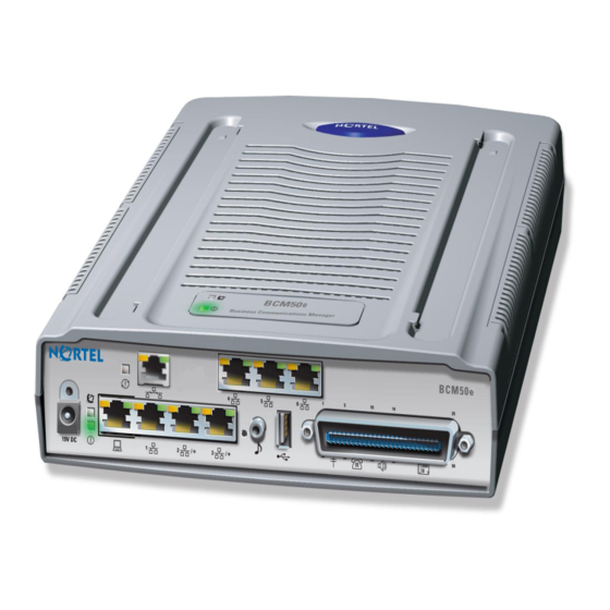
Page 30: Physical Features
Physical features 4-Port switch A combination of switch and router makes your BCM50e Integrated Router a cost effective and viable network solution. You can connect up to four computers or phones to the Business Secure Router without the cost of a switch. Use a switch to add more than four computers or phones to your LAN. -
Page 31: Autonegotiating 10/100 Mb/S Ethernet Wan
Chapter 1 Getting to know your BCM50e Integrated Router 31 Autonegotiating 10/100 Mb/s Ethernet WAN The 10/100 Mb/s Ethernet WAN port attaches to the Internet via broadband modem or router and automatically detects if it is on a 10 or a 100 Mb/s Ethernet. -
Page 32: Ssh
32 Chapter 1 Getting to know your BCM50e Integrated Router The Business Secure Router uses the SSH (Secure Shell) secure communication protocol to provide secure encrypted communication between two hosts over an unsecured network. HTTPS HyperText Transfer Protocol over Secure Socket Layer, or HTTP over SSL is a web protocol that encrypts and decrypts web sessions. -
Page 33: Universal Plug And Play (Upnp)
Chapter 1 Getting to know your BCM50e Integrated Router 33 Universal Plug and Play (UPnP) Using the standard TCP/IP protocol, the Business Secure Router and other UPnP-enabled devices can dynamically join a network, obtain an IP address, and convey its capabilities to other devices on the network. -
Page 34: Ip Alias
34 Chapter 1 Getting to know your BCM50e Integrated Router IP Alias Using IP Alias, you can partition a physical network into logical networks over the same Ethernet interface. The Business Secure Router supports three logical LAN interfaces via its single physical Ethernet LAN interface with the Business Secure Router itself as the gateway for each LAN network. -
Page 35: Port Forwarding
Chapter 1 Getting to know your BCM50e Integrated Router 35 Port Forwarding Use this feature to forward incoming service requests to a server on your local network. You can enter a single port number or a range of port numbers to be forwarded, and the local IP address of the desired server. -
Page 36: Upgrade Business Secure Router Firmware
Applications for the BCM50e Integrated Router Secure broadband internet access and VPN You can connect a cable, DSL, or other modem to the BCM50e Integrated Router via Ethernet WAN port for broadband Internet access. The Business Secure Router also provides IP address sharing and a firewall protected local network with traffic management. -
Page 37: Figure 1 Secure Internet Access And Vpn Application
Chapter 1 Getting to know your BCM50e Integrated Router 37 Figure 1 Secure Internet Access and VPN Application BCM50e Integrated Router BCM50e Integrated Router Configuration - Advanced... - Page 38 38 Chapter 1 Getting to know your BCM50e Integrated Router N0115789...
-
Page 39: Chapter 2 Introducing The Smt
=0, ethernet address: 00:A0:C5:22:1A:03 initialize ch =1, ethernet address: 00:A0:C5:22:1A:04 Press ENTER to continue... Logging on to the SMT The logon screen appears after you press [ENTER], prompting you to enter the username, as shown in Figure BCM50e Integrated Router Configuration - Advanced... -
Page 40: Navigating The Smt Interface
40 Chapter 2 Introducing the SMT Type the username (nnadmin is the default) and press [ENTER]. The logon screen prompts you to enter the password. Figure 3 SMT Login Enter Username : XXXX Enter Password : XXXX Type the password (PlsChgMe! is the default) and press [ENTER]. As you type the password, the screen displays an X for each character you type. -
Page 41: Main Menu
[ENTER] to exit the SMT interface. Main menu After you enter the password, the SMT displays the Business Secure Router Main Menu, as shown in Figure 4. Not all models have all the features shown. BCM50e Integrated Router Configuration - Advanced... -
Page 42: Figure 4 Main Menu
42 Chapter 2 Introducing the SMT Figure 4 Main menu Business Secure Router Main Menu Getting Started Advanced Management 1. General Setup 21. Filter and Firewall Setup 2. WAN Setup 22. SNMP Configuration 3. LAN Setup 23. System Security 4. Internet Access Setup 24. -
Page 43: Changing The System Password
Retype your new system password in the Retype to confirm field for confirmation and press [ENTER]. Note that as you type a password, the screen displays an asterisk * for each character you type. BCM50e Integrated Router Configuration - Advanced... -
Page 44: Smt Menus At A Glance
44 Chapter 2 Introducing the SMT SMT menus at a glance Figure 6 SMT overview N0115789... -
Page 45: Smt Menu 1 - General Setup
First System DNS Server= From ISP IP Address= N/A Second System DNS Server= From ISP IP Address= N/A Third System DNS Server= From ISP IP Address= N/A Edit Dynamic DNS= No Press ENTER to confirm or ESC to cancel: BCM50e Integrated Router Configuration - Advanced... -
Page 46: Table 4 General Setup Menu Fields
Example System name Choose a descriptive name for identification purposes. Business Nortel recommends you enter your computer name in Secure Router this field. This name can be up to 30 alphanumeric characters long. Spaces, dashes - and underscores _ are accepted. - Page 47 VPN peer. Enter the DNS server IP address in the field to the right. With a private DNS server, you must also configure the first DNS server entry in SMT menu 3.1 to use DNS Relay. BCM50e Integrated Router Configuration - Advanced...
-
Page 48: Configuring Dynamic Dns
48 Chapter 2 SMT menu 1 - general setup Table 4 General setup menu fields Field Description Example You must also configure a VPN branch office rule since the Business Secure Router uses a VPN tunnel when it relays DNS queries to the private DNS server. One of the rule’s IP policies must include the LAN IP address of the Business Secure Router as a local IP address and the IP address of the DNS server as a... -
Page 49: Figure 8 Configure Dynamic Dns
Enter the password assigned to you. Enable Wildcard Your Business Secure Router supports DYNDNS Wildcard. Press [SPACE BAR] and then [ENTER] to select Yes or No This field is N/A when you choose DDNS client as your service provider. BCM50e Integrated Router Configuration - Advanced... - Page 50 50 Chapter 2 SMT menu 1 - general setup Table 5 Configure dynamic DNS menu fields Field Description Example Offline This field is only available when CustomDNS is selected in the DDNS Type field. Press [SPACE BAR] and then [ENTER] to select Yes. http://www.dyndns.org/ When Yes is selected, traffic is redirected to a URL that you have...
-
Page 51: Wan Setup
This chapter describes how to configure the WAN using menu 2. Introduction to WAN setup This chapter explains how to configure settings for your WAN port. WAN setup From the main menu, enter 2 to open menu 2 BCM50e Integrated Router Configuration - Advanced... -
Page 52: Table 6 Mac Address Cloning In Wan Setup
52 Chapter 3 WAN Setup Figure 9 Menu 2 Menu 2 - WAN Setup MAC Address: Assigned By= Factory default IP Address= N/A Dial-Backup: Active= No Port Speed= 115200 AT Command String: Init= at&fs0=0 Edit Advanced Setup= No Press ENTER to Confirm or ESC to Cancel: Press Space Bar to Toggle. -
Page 53: Lan Setup
With Menu 3, you can specify the filter sets that you wish to apply to the LAN traffic. You seldom need to filter the LAN traffic, however, the filter sets are useful to block certain packets, reduce traffic, and prevent security breaches. BCM50e Integrated Router Configuration - Advanced... -
Page 54: Tcp/Ip And Dhcp Ethernet Setup Menu
54 Chapter 4 LAN setup Figure 11 Menu 3.1: LAN port filter setup Menu 3.1 – LAN Port Filter Setup Input Filter Sets: protocol filters= device filters= Output Filter Sets: protocol filters= device filters= Press ENTER to Confirm or ESC to Cancel: TCP/IP and DHCP ethernet setup menu From the main menu, enter 3 to open Menu 3 - LAN Setup to configure TCP/IP (RFC 1155) and DHCP Ethernet setup. -
Page 55: Figure 13 Figure 21-4 Menu 3.2: Tcp/Ip And Dhcp Ethernet Setup
DHCP server. If set to None, the DHCP server will be disabled. Configuration: Client IP Pool This field specifies the first of the contiguous 192.168.1.2 Starting Address addresses in the IP address pool. BCM50e Integrated Router Configuration - Advanced... - Page 56 56 Chapter 4 LAN setup Table 7 DHCP Ethernet setup menu fields Field Description Example Size of Client IP This field specifies the size or count of the IP Pool address pool. First DNS Server The Business Secure Router passes a DNS Second DNS (Domain Name System) server IP address (in the Server...
-
Page 57: Ip Alias Setup
You must use menu 3.2 to configure the first network. Move the cursor to the Edit IP Alias field, press [SPACE BAR] to choose Yes and press [ENTER] to configure the second and third network. Press [ENTER] to open Menu 3.2.1 - IP Alias Setup, as shown in Figure BCM50e Integrated Router Configuration - Advanced... -
Page 58: Figure 14 Menu 3.2.1: Ip Alias Setup
58 Chapter 4 LAN setup Figure 14 Menu 3.2.1: IP Alias setup Menu 3.2.1 - IP Alias Setup IP Alias 1= No IP Address= N/A IP Subnet Mask= N/A RIP Direction= N/A Version= N/A Incoming protocol filters= N/A Outgoing protocol filters= N/A IP Alias 2= No IP Address= N/A IP Subnet Mask= N/A... - Page 59 Filters incoming traffic between this node and the Business Secure Router. Outgoing Protocol Enter the filter sets you wish to apply to the Filters outgoing traffic between this node and the Business Secure Router. BCM50e Integrated Router Configuration - Advanced...
- Page 60 60 Chapter 4 LAN setup N0115789...
-
Page 61: Internet Access
4 screens, depending on whether you chose Ethernet, PPTP or PPPoE Encapsulation. Contact your ISP to determine which encapsulation type you should use. Ethernet encapsulation If you choose Ethernet in menu 4 you will see Figure BCM50e Integrated Router Configuration - Advanced... -
Page 62: Figure 15 Menu 4: Internet Access Setup (Ethernet)
62 Chapter 5 Internet access Figure 15 Menu 4: internet access setup (Ethernet) Menu 4 - Internet Access Setup ISP's Name= ChangeMe Encapsulation= Ethernet Service Type= Standard My Login= N/A My Password= N/A Retype to Confirm= N/A Login Server IP= N/A IP Address Assignment= Dynamic IP Address= N/A IP Subnet Mask= N/A... -
Page 63: Configuring The Pptp Client
Note: The Business Secure Router supports only one PPTP server connection at any given time. To configure a PPTP client, you must configure the My Login and Password fields for a PPP connection and the PPTP parameters for a PPTP connection. BCM50e Integrated Router Configuration - Advanced... -
Page 64: Configuring The Pppoe Client
64 Chapter 5 Internet access After configuring My Login and Password for PPP connection, press [SPACE BAR] and then [ENTER] in the Encapsulation field in Menu 4 -Internet Access Setup to choose PPTP as your encapsulation option. This brings up the screen show in Figure Figure 16 Internet access setup (PPTP) Menu 4 - Internet Access Setup... -
Page 65: Figure 17 Internet Access Setup (Pppoe)
PPPoE server. If you need a PPPoE service name to identify and reach the PPPoE server, go to menu 11 and enter the PPPoE service name provided to you in the Service Name field. BCM50e Integrated Router Configuration - Advanced... -
Page 66: Basic Setup Complete
WebGUI. You can also define additional firewall rules or modify existing ones, but exercise extreme caution in doing so. See the chapters on N0115788 firewalls in BCM50e Integrated Router Configuration - Basics ( ) for more information on the firewall. -
Page 67: Chapter 6 Remote Node Setup
From the main menu, select menu option 11 to open Menu 11 Remote Node Setup (Figure 18). Enter 1 to open Menu 11.1 Remote Node Profile and configure the setup for your regular ISP. BCM50e Integrated Router Configuration - Advanced... -
Page 68: Remote Node Profile Setup
68 Chapter 6 Remote Node setup Figure 18 Menu 11 Remote Node Setup Menu 11 - Remote Node Setup 1. ChangeMe (ISP, SUA) 2. -GUI (BACKUP_ISP, SUA) Enter Node # to Edit: Remote Node profile setup This section explains how to configure the remote node profile menu. Ethernet Encapsulation There are two variations of menu 11.1 depending on whether you choose Ethernet Encapsulation or PPPoE Encapsulation. -
Page 69: Figure 19 Menu 11.1: Remote Node Profile For Ethernet Encapsulation
Press [SPACE BAR] and then [ENTER] to select from Standard Standard, RR-Toshiba (Road Runner Toshiba authentication method) or RR-Manager (Road Runner Manager authentication method). Choose one of the Road Runner methods if your ISP is Time Warner's Road Runner; otherwise choose Standard. BCM50e Integrated Router Configuration - Advanced... -
Page 70: Pppoe Encapsulation
70 Chapter 6 Remote Node setup Table 13 Fields in menu 11.1 Field Description Example Service Name If you are using PPPoE encapsulation, then type the poellc name of your PPPoE service here. Only valid with PPPoE encapsulation. Outgoing This field is applicable for PPPoE encapsulation only. Enter the logon name assigned by your ISP when the My Login Business Secure Router calls this remote node. -
Page 71: Outgoing Authentication Protocol
If you encounter a case where the peer disconnects right after a successful authentication, make sure that you specify the correct authentication protocol when connecting to such an implementation. BCM50e Integrated Router Configuration - Advanced... -
Page 72: Nailed-Up Connection
72 Chapter 6 Remote Node setup Nailed-Up Connection A nailed-up connection is a dial-up line where the connection is always up, regardless of traffic demand. The Business Secure Router does two things when you specify a nailed-up connection. The first is that idle timeout is disabled. The second is that the Business Secure Router tries to bring up the connection when turned on and whenever the connection is down. -
Page 73: Pptp Encapsulation
Enter the IP address of the WAN Ethernet port. 10.0.0.140 My IP Mask Enter the subnet mask of the WAN Ethernet port. 255.255.255.0 My Server IP Addr Enter the IP address of the ANT modem. 10.0.0.138 BCM50e Integrated Router Configuration - Advanced... -
Page 74: Edit Ip
74 Chapter 6 Remote Node setup Table 15 Fields in Menu 11.1 (PPTP Encapsulation) Field Description Example Connection ID/ Enter the connection ID or connection name in the N:My ISP Name ANT. It must follow the “c:id” and “n:name” format. This field is optional and depends on the requirements of your DSL modem. -
Page 75: Figure 22 Menu 11.1.2: Remote Node Network Layer Options For Ethernet Encapsulation
If you have a Static IP Assignment, enter the IP address Address assigned to you by your ISP. (Rem) IP If you have a Static IP Assignment, enter the subnet mask Subnet Mask assigned to you. BCM50e Integrated Router Configuration - Advanced... - Page 76 RIP Direction Press [SPACE BAR] and then [ENTER] to select the RIP None direction from Both/ None/In Only/Out Only. The default (default) for RIP on the WAN side is None. Nortel recommends that you do not change this setting. N0115789...
-
Page 77: Remote Node Filter
For more information about defining the filters, refer to Chapter 11, “Filter configuration,” on page 117. For PPPoE or PPTP encapsulation, you have the additional option of specifying remote node call filter sets. BCM50e Integrated Router Configuration - Advanced... -
Page 78: Figure 23 Menu 11.1.4: Remote Node Filter (Ethernet Encapsulation)
78 Chapter 6 Remote Node setup Figure 23 Menu 11.1.4: Remote Node filter (Ethernet Encapsulation) Menu 11.1.4 - Remote Node Filter Input Filter Sets: protocol filters= device filters= Output Filter Sets: protocol filters= device filters= Enter here to CONFIRM or ESC to CANCEL: Figure 24 Menu 11.1.4: Remote Node filter (PPPoE or PPTP Encapsulation) Menu 11.1.4 - Remote Node Filter Input Filter Sets:... -
Page 79: Figure 25 Menu 11.1: Remote Node Profile
Select Yes and press [ENTER] to configure Menu 11.1.5 — Traffic Redirect Setup. Press [ENTER] at the message “Press ENTER to Confirm...” to save your configuration, or press [ESC] at any time to cancel. BCM50e Integrated Router Configuration - Advanced... -
Page 80: Traffic Redirect Setup
80 Chapter 6 Remote Node setup Traffic Redirect setup Configure parameters that determine when the Business Secure Router forwards WAN traffic to the backup gateway using Menu 11.1.5 — Traffic Redirect Setup. Figure 26 Menu 11.1.5: Traffic Redirect setup Menu 11.1.5 - Traffic Redirect Setup Active= Yes Configuration: Backup Gateway IP Address= 0.0.0.0... - Page 81 After you complete this menu, press [ENTER] at the prompt “Press [ENTER] to confirm or [ESC] to cancel” to save your configuration or press [ESC] to cancel and go back to the previous screen. BCM50e Integrated Router Configuration - Advanced...
- Page 82 82 Chapter 6 Remote Node setup N0115789...
-
Page 83: Ip Static Route Setup
Figure 27 Menu 12: IP Static Route Setup Menu 12 - IP Static Route Setup 1. Reserved 2. ________ 3. ________ 4. ________ 5. ________ 6. ________ 7. ________ 8. ________ 9. ________ 10. ________ 11. ________ BCM50e Integrated Router Configuration - Advanced... -
Page 84: Figure 28 Menu 12. 1: Edit Ip Static Route
84 Chapter 7 IP Static Route Setup 12. ________ Enter selection number: Now, enter the index number of the static route that you want to configure. Figure 28 Menu 12. 1: Edit IP Static Route Menu 12.1 - Edit IP Static Route Route #: 2 Route Name= ? Active= No... - Page 85 RIP broadcasts. After you complete filling in this menu, press [ENTER] at the message “Press ENTER to Confirm…” to save your configuration, or press [ESC] to cancel. BCM50e Integrated Router Configuration - Advanced...
- Page 86 86 Chapter 7 IP Static Route Setup N0115789...
-
Page 87: Chapter 8 Dial-In User Setup
22. ________ 30. ________ 7. ________ 15. ________ 23. ________ 31. ________ 8. ________ 16. ________ 24. ________ 32. ________ Enter Menu Selection Number: Type a number and press [ENTER] to edit the user profile. BCM50e Integrated Router Configuration - Advanced... -
Page 88: Figure 30 Menu 14.1- Edit Dial-In User
88 Chapter 8 Dial-in User Setup Figure 30 Menu 14.1- Edit Dial-in User Menu 14.1 - Edit Dial-in User User Name= test Active= Yes Password= ******** Press ENTER to Confirm or ESC to Cancel: Leave name field blank to delete profile Table 20 describes the fields in Figure... -
Page 89: Network Address Translation (Nat)
(Figure 32 on page 91). Figure 31 shows you how to apply NAT for Internet access in menu 4. Enter 4 from the main menu to go to Menu 4 - Internet Access Setup. BCM50e Integrated Router Configuration - Advanced... -
Page 90: Figure 31 Menu 4: Applying Nat For Internet Access
90 Chapter 9 Network Address Translation (NAT) Figure 31 Menu 4: Applying NAT for Internet Access Menu 4 - Internet Access Setup ISP's Name= ChangeMe Encapsulation= Ethernet Service Type= Standard My Login= N/A My Password= N/A Retype to Confirm= N/A Login Server= N/A IP Address Assignment= Dynamic IP Address= N/A... -
Page 91: Figure 32 Menu 11.1.2: Applying Nat To The Remote Node
When you select this option the SMT uses Address SUA Only Mapping Set 255 (menu 15.1 - “Address Mapping Sets” on page 92). Choose SUA Only if you have just one public WAN IP address for your Business Secure Router. BCM50e Integrated Router Configuration - Advanced... -
Page 92: Nat Setup
92 Chapter 9 Network Address Translation (NAT) NAT setup Use the address mapping sets menus and submenus to create the mapping table used to assign global addresses to computers on the LAN. You can see two NAT address mapping sets in menu 15.1. You can only configure Set 1. Set 255 is used for SUA. -
Page 93: Sua Address Mapping Set
Enter Menu Selection Number: SUA Address Mapping Set Enter 255 to display the screen shown in Figure 35 (see “SUA (Single User Account) Versus NAT” on page 89). The fields in this menu cannot be changed. BCM50e Integrated Router Configuration - Advanced... -
Page 94: Figure 35 Menu 15.1.255: Sua Address Mapping Rules
94 Chapter 9 Network Address Translation (NAT) Figure 35 Menu 15.1.255: SUA Address Mapping Rules Menu 15.1.255 - Address Mapping Rules Set Name= SUA Local Start IP Local End IP Global Start IP Global End IP Type --------------- --------------- --------------- --------------- ------ 0.0.0.0... -
Page 95: User-Defined Address Mapping Sets
Name field means that this is a required field and you must enter a name for the set. Note: The entire set is deleted if you leave the Set Name field blank and press [ENTER] at the bottom of the screen. BCM50e Integrated Router Configuration - Advanced... -
Page 96: Ordering Your Rules
96 Chapter 9 Network Address Translation (NAT) Figure 36 Menu 15.1.1: First Set Menu 15.1.1 - Address Mapping Rules Set Name= NAT_SET Local Start IP Local End IP Global Start IP Global End IP Type --------------- --------------- --------------- --------------- ------ Action= Edit Select Rule= Press ENTER to Confirm or ESC to Cancel:... -
Page 97: Table 23 Fields In Menu 15.1.1
37, Menu 15.1.1.1 - Address Mapping Rule in which you can edit an individual rule and configure the Type, Local and Global Start/End IPs. Note: An IP End address must be numerically greater than its corresponding IP Start address. BCM50e Integrated Router Configuration - Advanced... -
Page 98: Figure 37 Menu 15.1.1.1: Editing Or Configuring An Individual Rule In A Set
98 Chapter 9 Network Address Translation (NAT) Figure 37 Menu 15.1.1.1: Editing or configuring an individual rule in a set Menu 15.1.1.1 Address Mapping Rule Type= One-to-One Local IP: Start= = N/A Global IP: Start= = N/A Press ENTER to Confirm or ESC to Cancel: Table 24 describes the fields in Figure... -
Page 99: Configuring A Server Behind Nat
Follow these steps to configure a server behind NAT: Enter 15 in the main menu to go to Menu 15 - NAT Setup. Enter 2 to go to Menu 15.2 - NAT Server Setup. BCM50e Integrated Router Configuration - Advanced... -
Page 100: Figure 38 Menu 15.2: Nat Server Sets
100 Chapter 9 Network Address Translation (NAT) Figure 38 Menu 15.2: NAT Server Sets Menu 15.2 - NAT Server Setup Default Server: 0.0.0.0 Rule Act. Start Port End Port IP Address ------------------------------------------------------ 0.0.0.0 0.0.0.0 0.0.0.0 0.0.0.0 0.0.0.0 0.0.0.0 0.0.0.0 0.0.0.0 0.0.0.0 0.0.0.0 Select Command= None... -
Page 101: Figure 39 15.2.1: Nat Server Configuration
Enter a port number in the Start Port field. To forward only one port, enter it again in the End Port field. To specify a range of ports, enter the last port to be forwarded in the End Port field. BCM50e Integrated Router Configuration - Advanced... -
Page 102: Figure 40 Menu 15.2: Nat Server Setup
102 Chapter 9 Network Address Translation (NAT) Enter the inside IP address of the server in the IP Address field. In the following figure, you have a computer acting as an FTP, Telnet and SMTP server (ports 21, 23 and 25) at 192.168.1.33. Press [ENTER] at the “Press ENTER to confirm …”... -
Page 103: General Nat Examples
Figure 42, you only need one rule where all your ILAs (Inside Local addresses) map to one dynamic IGA (Inside Global Address) assigned by your ISP. Figure 42 NAT Example 1 BCM50e Integrated Router BCM50e Integrated Router Configuration - Advanced... -
Page 104: Figure 43 Menu 4: Internet Access & Nat Example
104 Chapter 9 Network Address Translation (NAT) Figure 43 Menu 4: Internet access & NAT example Menu 4 - Internet Access Setup ISP's Name= ChangeMe Encapsulation= Ethernet Service Type= Standard My Login= N/A My Password= N/A Login Server IP= N/A IP Address Assignment= Dynamic IP Address= N/A IP Subnet Mask= N/A... -
Page 105: Example 2: Internet Access With An Inside Server
In this case, you do exactly as shown in Figure 44 (use the convenient pre-configured SUA Only set), and also go to menu 15.2 to specify the Inside Server behind the NAT as shown in Figure BCM50e Integrated Router Configuration - Advanced... -
Page 106: Example 3: Multiple Public Ip Addresses With Inside Servers
106 Chapter 9 Network Address Translation (NAT) Figure 45 Menu 15.2: Specifying an inside server Menu 15.2 - NAT Server Setup Default Server: 192.168.1.10 Rule Act. Start Port End Port IP Address ------------------------------------------------------ 0.0.0.0 0.0.0.0 0.0.0.0 0.0.0.0 0.0.0.0 0.0.0.0 0.0.0.0 0.0.0.0 0.0.0.0 0.0.0.0... -
Page 107: Figure 46 Nat Example 3
Start IP as 10.132.50.1 (our first IGA). (see Figure 48). Repeat the previous step for rules 2 to 4 as outlined above. When finished, menu 15.1.1 looks like as shown in Figure BCM50e Integrated Router Configuration - Advanced... -
Page 108: Figure 47 Example 3: Menu 11.1.2
108 Chapter 9 Network Address Translation (NAT) Figure 47 Example 3: Menu 11.1.2 Menu 11.1.2 - Remote Node Network Layer Options IP Address Assignment= Dynamic IP Address= N/A IP Subnet Mask= N/A Gateway IP Addr= N/A Network Address Translation= Full Feature Metric= N/A Private= N/A RIP Direction= None... -
Page 109: Figure 48 Example 3: Menu 15.1.1.1
Chapter 9 Network Address Translation (NAT) 109 Figure 48 Example 3: Menu 15.1.1.1 Menu 15.1.1.1 Address Mapping Rule Type= One-to-One Local IP: Start= 192.168.1.10 = N/A Global IP: Start= 10.132.50.1 = N/A Press ENTER to Confirm or ESC to Cancel: BCM50e Integrated Router Configuration - Advanced... -
Page 110: Figure 49 Example 3: Final Menu 15.1.1
110 Chapter 9 Network Address Translation (NAT) Figure 49 Example 3: Final Menu 15.1.1 Menu 15.1.1 - Address Mapping Rules Set Name= Example3 Local Start IP Local End IP Global Start IP Global End IP Type --------------- --------------- --------------- --------------- ------ 1. -
Page 111: Configuring Trigger Port Forwarding
Configuring Trigger Port forwarding Note: Only one LAN computer can use a trigger port (range) at a time. Enter 3 in menu 15 to display Menu 15.3 — Trigger Port Setup, shown in Figure BCM50e Integrated Router Configuration - Advanced... -
Page 112: Figure 51 Menu 15.3: Trigger Port Setup
112 Chapter 9 Network Address Translation (NAT) Figure 51 Menu 15.3: Trigger Port Setup Menu 15.3 - Trigger Port Setup Incoming Trigger Rule Name Start Port End Port Start Port End Port ---------------------------------------------------------------------- 1. Real Audio 6970 7170 7070 7070 Press ENTER to Confirm or ESC to Cancel: Table 26 describes the fields in... - Page 113 Enter a port number or the ending port number in a range of port 7070 numbers. Press [ENTER] at the message “Press ENTER to Confirm...” to save your configuration, or press [ESC] at any time to cancel. BCM50e Integrated Router Configuration - Advanced...
- Page 114 114 Chapter 9 Network Address Translation (NAT) N0115789...
-
Page 115: Introducing The Firewall
[SPACE BAR] and then [ENTER] to select Yes in the Active field to activate the firewall. The firewall must be active to protect against Denial of Service (DoS) attacks. Use the WebGUI to configure firewall rules. BCM50e Integrated Router Configuration - Advanced... -
Page 116: Figure 53 Menu 21.2: Firewall Setup
116 Chapter 10 Introducing the firewall Figure 53 Menu 21.2: Firewall Setup Menu 21.2 - Firewall Setup The firewall protects against Denial of Service (DoS) attacks when it is active. Your network is vulnerable to attacks when the firewall is turned off. Refer to the User’s Guide for details about the firewall default policies. -
Page 117: Chapter 11 Filter Configuration
LAN side. Call filtering is used to determine if a packet is allowed to trigger a call. Remote node call filtering is only applicable when using PPPoE encapsulation. Outgoing packets must undergo data filtering before they encounter call filtering as shown in Figure BCM50e Integrated Router Configuration - Advanced... -
Page 118: Filter Structure
118 Chapter 11 Filter configuration Figure 54 Outgoing packet filtering process C a ll F ilt e r in g A c t iv e D a t a B u ilt - in U s e r - d e f in e d D a t a m a t c h m a t c h... -
Page 119: Figure 55 Filter Rule Process
You can apply up to four filter sets to a particular port to block multiple types of packets. With each filter set having up to six rules, you can have a maximum of 24 rules active for a single port. BCM50e Integrated Router Configuration - Advanced... -
Page 120: Configuring A Filter Set
120 Chapter 11 Filter configuration Configuring a Filter Set The Business Secure Router includes filtering for NetBIOS over TCP/IP packets by default. To configure another filter set, follow the procedure below. Enter 21 in the main menu to open menu 21. Figure 56 Menu 21: Filter and Firewall Setup Menu 21 - Filter and Firewall Setup 1. -
Page 121: Figure 57 Menu 21.1: Filter Set Configuration
21.1.1 - Filter Rules Summary. The screen shown in Figure 58 shows the summary of the existing rules in the filter set. Table 27 Table 28 contain a brief description of the abbreviations used in the previous menus. BCM50e Integrated Router Configuration - Advanced... -
Page 122: Table 27 Abbreviations Used In The Filter Rules Summary Menu
122 Chapter 11 Filter configuration Table 27 Abbreviations used in the Filter Rules Summary Menu Field Description The filter rule number: 1 to 6. Active: “Y” means the rule is active. “N” means the rule is inactive. Type The type of filter rule: “GEN” for Generic, “IP” for TCP/IP. Filter Rules These parameters are displayed here. -
Page 123: Configuring A Filter Rule
IP and the upper layer protocol, for example, UDP and TCP headers. To configure TCP/IP rules, select TCP/IP Filter Rule from the Filter Type field and press [ENTER] to open Menu 21.1.1.1 - TCP/IP Filter Rule, as shown in Figure BCM50e Integrated Router Configuration - Advanced... -
Page 124: Figure 58 Menu 21.1.1.1: Tcp/Ip Filter Rule
124 Chapter 11 Filter configuration Figure 58 Menu 21.1.1.1: TCP/IP Filter Rule Menu 21.1.1.2 - TCP/IP Filter Rule Filter #: 1,2 Filter Type= TCP/IP Filter Rule Active= Yes IP Protocol= 0 IP Source Route= No Destination: IP Addr= IP Mask= Port #= Port # Comp= None Source: IP Addr=... - Page 125 No, the packet is disposed of according to the action fields. If More is Yes, then Action Matched and Action Not Matched will be N/A. BCM50e Integrated Router Configuration - Advanced...
- Page 126 126 Chapter 11 Filter configuration Table 29 TCP/IP Filter Rule Menu fields Field Description Options Press [SPACE BAR] and then [ENTER] to select a None logging option from the following: Action None – No packets are logged. Matched Action Matched - Only packets that match the rule Action Not parameters are logged.
-
Page 127: Figure 59 Executing An Ip Filter
IP Protocol Matched Check Src & Not Matched Dest Port Matched More? Action Not Matched Action Matched Check Next Rule Check Next Rule Drop Forward Drop Forward Drop Packet Check Next Rule Accept Packet BCM50e Integrated Router Configuration - Advanced... -
Page 128: Configuring A Generic Filter Rule
128 Chapter 11 Filter configuration Configuring a Generic Filter Rule This section shows you how to configure a generic filter rule. With generic rules you can filter non-IP packets. For IP packets, it is generally easier to use the IP rules directly. -
Page 129: Table 30 Generic Filter Rule Menu Fields
Action Not Matched - Only packets that do not match the Matched rule parameters are logged. Both Both – All packets are logged. Action Select the action for a packet matching the rule. Check Next Matched Rule Forward Drop BCM50e Integrated Router Configuration - Advanced... -
Page 130: Example Filter
Business Secure Router via Telnet. See the included disk for more Filter Rules example. Figure 61 Telnet filter Example BCM50e Integrated Router Enter 21 from the main menu to open Menu 21 - Filter and Firewall Setup. Enter 1 to open Menu 21.1 - Filter Set Configuration. -
Page 131: Figure 9 Menu 2
The action is to drop the packet (m = D) if the action is matched and to forward the packet immediately (n = F) if the action is not matched, whether or not there are more rules to be checked (there are none in this example). BCM50e Integrated Router Configuration - Advanced... -
Page 132: Figure 63 Example Filter Rules Summary: Menu 21.1.3
132 Chapter 11 Filter configuration Figure 63 Example Filter Rules Summary: Menu 21.1.3 Menu 21.1.3 - Filter Rules Summary # A Type Filter Rules M m n - - ---- --------------------------------------------------------------- - 1 Y IP Pr=6, SA=0.0.0.0, DA=0.0.0.0, DP=23 N D F Enter Filter Rule Number (1-6) to Configure: 1 After you have created the filter set, you must apply it. -
Page 133: Filter Types And Nat
Figure 64 Protocol and Device Filter Sets Firewall Versus Filters Firewall configuration is discussed in Chapter 10, “Introducing the firewall,” on page 115 chapters of this manual. Further comparisons are also made between filtering, NAT and the firewall. BCM50e Integrated Router Configuration - Advanced... -
Page 134: Applying A Filter
This section shows you where to apply the filters after you design them. The Business Secure Router already has filters to prevent NetBIOS traffic from triggering calls, and block incoming Telnet, FTP and HTTP connections. Note: Nortel recommends that you apply filters if you do not activate the firewall. Applying LAN Filters LAN traffic filter sets are useful to block certain packets, reduce traffic and prevent security breaches. -
Page 135: Applying Remote Node Filters
Figure 66 Filtering Remote Node Traffic Menu 11.1.4 – Remote Node Filter Setup Input Filter Sets: protocol filters= device filters= Output Filter Sets: protocol filters= device filters= Press ENTER to Confirm or ESC to Cancel: BCM50e Integrated Router Configuration - Advanced... - Page 136 136 Chapter 11 Filter configuration N0115789...
-
Page 137: Chapter 12 Snmp Configuration
SNMP terminology for password. Figure 67 Menu 22: SNMP Configuration Menu 22 - SNMP Configuration SNMP: Get Community= Set Community= Trusted Host= 0.0.0.0 Trap: Community= Destination= 0.0.0.0 Press ENTER to Confirm or ESC to Cancel: BCM50e Integrated Router Configuration - Advanced... -
Page 138: Snmp Traps
138 Chapter 12 SNMP Configuration Table 31 describes the SNMP configuration parameters. Table 31 SNMP Configuration Menu Fields Field Description Example Get Community Type the Get community, which is the password for Public the incoming Get- and GetNext requests from the (default) management station. - Page 139 (for example, download new files, CI command "sys reboot", and others). For fatal error: A trap is sent with the message of the fatal code if the system reboots because of fatal errors. BCM50e Integrated Router Configuration - Advanced...
- Page 140 140 Chapter 12 SNMP Configuration N0115789...
-
Page 141: Chapter 13 System Security
2. RADIUS Server 4. IEEE802.1x Enter Menu Selection Number: Nortel recommends you change the default password. If you forget your password, you have to restore the default configuration file. For more information, see “Restoring the factory-default configuration settings” in BCM50e... -
Page 142: Configuring External Radius Server
142 Chapter 13 System security Configuring external RADIUS server Enter 23 in the main menu to display Menu 23 – System security. Figure 69 Menu 23 system security Menu 23 - System Security 1. Change Password 2. RADIUS Server 4. IEEE802.1x Enter Menu Selection Number: From Menu 23- System Security, enter 2 to display Menu 23.2 –... -
Page 143: Table 33 Menu 23.2 System Security: Radius Server
After you complete this menu, press [ENTER] at the prompt “Press ENTER to confirm or ESC to cancel” to save your configuration or press [ESC] to cancel and go back to the previous screen. BCM50e Integrated Router Configuration - Advanced... - Page 144 144 Chapter 13 System security N0115789...
-
Page 145: System Information And Diagnosis
Secure Router. These tools include updates on system status, port status and log and trace capabilities. Select menu 24 in the main menu to open Menu 24 - System Maintenance, as shown in Figure BCM50e Integrated Router Configuration - Advanced... -
Page 146: System Status
146 Chapter 14 System information and diagnosis Figure 71 Menu 24: System Maintenance Menu 24 - System Maintenance 1. System Status 2. System Information and Console Port Speed 3. Log and Trace 4. Diagnostic 5. Backup Configuration 6. Restore Configuration 7. -
Page 147: Figure 72 Menu 24.1: System Maintenance: Status
Cols The number of collisions on this port. Tx B/s Shows the transmission speed in Bytes per second on this port. Rx B/s Shows the reception speed in Bytes per second on this port. BCM50e Integrated Router Configuration - Advanced... -
Page 148: System Information And Console Port Speed
148 Chapter 14 System information and diagnosis Table 34 System Maintenance: Status Menu Fields Field Description Up Time Total amount of time the line has been up. Ethernet Address The Ethernet address of the port listed on the left. IP Address The IP address of the port listed on the left. -
Page 149: System Information
2. Console Port Speed Please enter selection: System Information System Information gives you information about your system, as shown in Figure 75. More specifically, it gives you information on your routing protocol, Ethernet address and IP address. BCM50e Integrated Router Configuration - Advanced... -
Page 150: Figure 75 Menu 24.2.1: System Maintenance Information
150 Chapter 14 System information and diagnosis Figure 75 Menu 24.2.1: System Maintenance Information Menu 24.2.1 - System Maintenance - Information Name: Routing: IP RAS F/W Version: VBCM222_2.6.0.0.002 | 07/24/2006 Country Code: 255 Ethernet Address: 00:13:49:00:00:01 IP Address: 192.168.1.1 IP Mask: 255.255.255.0 DHCP: Server Press ESC or RETURN to Exit: Table 35 Fields in System Maintenance: Information... -
Page 151: Console Port Speed
The Business Secure Router uses the syslog facility to log the CDR (Call Detail Record) and system messages to a syslog server. Syslog and accounting can be configured in Menu 24.3.2 - System Maintenance - Syslog Logging, as shown Figure BCM50e Integrated Router Configuration - Advanced... -
Page 152: Cdr
152 Chapter 14 System information and diagnosis Figure 78 Menu 24.3.2: System Maintenance: Syslog Logging Menu 24.3.2 - System Maintenance - Syslog Logging Syslog: Active= No Syslog Server IP Address= ? Log Facility= Local 1 Press ENTER to Confirm or ESC to Cancel Configure the syslog parameters described in Table 36 to activate syslog, and then... -
Page 153: Packet Triggered
Jul 19 11:28:56 192.168.102.2 RAS: Packet Trigger: Protocol=1, Data=4500002c1b0140001f06b50ec0a86614ca849a7b0427001700195b3e00000000600 220008cd40000020405b4 Jul 19 11:29:06 192.168.102.2 RAS: Packet Trigger: Protocol=1, Data=45000028240140001f06ac12c0a86614ca849a7b0427001700195b451d143013500 4000077600000 Filter log Filter log Message Format SdcmdSyslogSend(SYSLOG_FILLOG, SYSLOG_NOTICE, String ); String = IP[Src=xx.xx.xx.xx Dst=xx.xx.xx.xx prot spo=xxxx dpo=xxxx] S04>R01mD BCM50e Integrated Router Configuration - Advanced... -
Page 154: Ppp Log
154 Chapter 14 System information and diagnosis IP[…] is the packet header and S04>R01mD means filter set 4 (S) and rule 1 (R), match (m) drop (D). Src: Source Address Dst: Destination Address prot: Protocol (“TCP”,”UDP”,”ICMP”) spo: Source port dpo: Destination port Mar 03 10:39:43 202.132.155.97 RAS: GEN[fffffffffffnordff0080] }S05>R01mF Mar 03 10:41:29 202.132.155.97 RAS:... -
Page 155: Firewall Log
IP Frame: ENET0-RECV Size: 44/ 44 Time: 17:02:44.262 Frame Type: IP Header: IP Version = 4 Header Length = 20 Type of Service = 0x00 (0) Total Length = 0x002C (44) Identification = 0x0002 (2) BCM50e Integrated Router Configuration - Advanced... - Page 156 156 Chapter 14 System information and diagnosis Flags = 0x00 Fragment Offset = 0x00 Time to Live = 0xFE (254) Protocol = 0x06 (TCP) Header Checksum = 0xFB20 (64288) Source IP = 0xC0A80101 (192.168.1.1) Destination IP = 0x00000000 (0.0.0.0) TCP Header: Source Port = 0x0401 (1025) Destination Port = 0x000D (13) Sequence Number = 0x05B8D000 (95997952)
-
Page 157: Wan Dhcp
Host IP Address= N/A WAN DHCP DHCP functionality can be enabled on the LAN or WAN as shown in WAN & LAN DHCP. LAN DHCP is discussed in BCM50e Integrated Router N0115788 Configuration - Basics ( ). The Business Secure Router can act either as a WAN DHCP client (IP Address Assignment field in menu 4 or menu 11.1.2 is... -
Page 158: Figure 81 Wan & Lan Dhcp
158 Chapter 14 System information and diagnosis Figure 81 WAN & LAN DHCP BCM50e Integrated Router Table 37 describes the diagnostic tests available in menu 24.4 for your Business Secure Router and associated connections. Table 37 System Maintenance menu diagnostic... -
Page 159: Firmware And Configuration File Maintenance
This is a sample FTP session showing the transfer of the computer file firmware.bin to the Business Secure Router. ftp> get rom-0 config.cfg This is a sample FTP session saving the current configuration to the computer file config.cfg. BCM50e Integrated Router Configuration - Advanced... -
Page 160: Backup Configuration
160 Chapter 15 Firmware and configuration file maintenance If your (T)FTP client does not allow you to have a destination filename different than the source, you must rename the firmware and config file names as the Business Secure Router only recognizes rom-0 and ras. Be sure you keep unaltered copies of both files for later use. -
Page 161: Backup Configuration
Business Secure Router to your computer and renames it config.rom. See earlier in this chapter for more information on filename conventions. Enter quit to exit the ftp prompt. BCM50e Integrated Router Configuration - Advanced... -
Page 162: Example Of Ftp Commands From The Command Line
162 Chapter 15 Firmware and configuration file maintenance Example of FTP commands from the command line Figure 83 FTP Session Example 331 Enter PASS command Password: 230 Logged in ftp> bin 200 Type I OK ftp> get rom-0 config.rom 200 Port command okay 150 Opening data connection for STOR ras 226 File received OK ftp: 16384 bytes sent in 1.10Seconds 297.89Kbytes/sec. -
Page 163: Backup Configuration Using Tftp
The Business Secure Router supports the uploading and downloading of the firmware and the configuration file using TFTP (Trivial File Transfer Protocol) over LAN. Nortel does not recommend using TFTP over WAN, although it can work. To use TFTP, your computer must have both Telnet and TFTP clients. To back up the configuration file, follow the procedure shown next. -
Page 164: Tftp Command Example
164 Chapter 15 Firmware and configuration file maintenance Use the TFTP client (see the example below) to transfer files between the Business Secure Router and the computer. The file name for the configuration file is “rom-0” (rom-zero, not capital o). Note: Telnet connection must be active and the SMT must be in CI mode before and during the TFTP transfer. -
Page 165: Restore Configuration
Warning: Do not interrupt the file transfer process as this can permanently damage your Business Secure Router. Restore Using FTP For details about back up using FTP and TFTP, refer to “Backup configuration” on page 160. BCM50e Integrated Router Configuration - Advanced... -
Page 166: Figure 84 Telnet Into Menu 24.6
166 Chapter 15 Firmware and configuration file maintenance Figure 84 Telnet into Menu 24.6 Menu 24.6 -- System Maintenance - Restore Configuration To transfer the firmware and configuration file to your workstation, follow the procedure below: 1. Launch the FTP client on your workstation. 2. -
Page 167: Restore Using Ftp Session Example
FTP is the preferred method for uploading the firmware and configuration. To use this feature, your computer must have an FTP client. When you use Telnet to access the Business Secure Router, the screens for uploading firmware and the configuration file using FTP appear. BCM50e Integrated Router Configuration - Advanced... -
Page 168: Configuration File Upload
168 Chapter 15 Firmware and configuration file maintenance Figure 86 Telnet Into Menu 24.7.1 Upload System Firmware Menu 24.7.1 - System Maintenance - Upload System Firmware To upload the system firmware, follow the procedure below: 1. Launch the FTP client on your workstation. 2. -
Page 169: Ftp File Upload Command From The Dos Prompt Example
Router to your computer and renames it “config.rom.” See “Filename conventions” on page 159 for more information about filename conventions. Enter “quit” to exit the ftp prompt. Note: The Business Secure Router automatically restarts after a successful file upload. BCM50e Integrated Router Configuration - Advanced... -
Page 170: Ftp Session Example Of Firmware File Upload
The Business Secure Router also supports the uploading of firmware files using TFTP (Trivial File Transfer Protocol) over LAN. Although TFTP also works over WAN, Nortel does not recommend doing this. To use TFTP, your computer must have both Telnet and TFTP clients. To transfer the firmware and the configuration file, follow the procedure shown next. -
Page 171: Tftp Upload Command Example
(firmware.bin – name of the firmware on the computer) to the file destination on the remote host (ras - name of the firmware on the Business Secure Router). Commands that appear in GUI-based TFTP clients are listed earlier in this chapter. BCM50e Integrated Router Configuration - Advanced... - Page 172 172 Chapter 15 Firmware and configuration file maintenance N0115789...
-
Page 173: System Maintenance Menus 8 To 10
Enter the CI from the SMT by selecting menu 24.8. Access can be by Telnet connection, although some commands are only available with a serial connection. See the included disk or www.nortel.com for more detailed information about CI commands. Enter 8 from Menu 24 - System Maintenance. -
Page 174: Command Syntax
174 Chapter 16 System Maintenance menus 8 to 10 Figure 89 Command mode in Menu 24 Menu 24 - System Maintenance 1. System Status 2. System Information and Console Port Speed 3. Log and Trace 4. Diagnostic 5. Backup Configuration 6. -
Page 175: Command Usage
This commands display IPSec information and configure IPSec settings. This commands display bandwidth management information and configure bandwidth management settings. certificates This commands display certificate information and configure certificate settings. radius This commands display RADIUS information. BCM50e Integrated Router Configuration - Advanced... -
Page 176: Call Control Support
176 Chapter 16 System Maintenance menus 8 to 10 Call control support The Business Secure Router provides two call control functions: budget management and call history. Note that this menu is only applicable when Encapsulation is set to PPPoE or PPTP in menu 4 or menu 11.1. With the budget management function, you can set a limit on the total outgoing call time of the Business Secure Router within certain times. -
Page 177: Figure 92 Budget Management
11.1.) The elapsed time is the 1-hour time period has time used up within this period. lapsed. Enter “0” to update the screen or press [ESC] to return to the previous screen. BCM50e Integrated Router Configuration - Advanced... -
Page 178: Call History
178 Chapter 16 System Maintenance menus 8 to 10 Call History This is the second option in Menu 24.9 - System Maintenance - Call Control. It displays information about past incoming and outgoing calls. Enter 2 from Menu 24.9 - System Maintenance - Call Control. Figure 93 Call History Menu 24.9.2 - Call History Phone Number... -
Page 179: Time And Date Setting
Enter Menu Selection Number: Enter 10 to go to Menu 24.10 - System Maintenance - Time and Date Setting to update the time and date settings of your Business Secure Router, as shown in Figure BCM50e Integrated Router Configuration - Advanced... -
Page 180: Figure 95 Menu 24.10 System Maintenance: Time And Date Setting
180 Chapter 16 System Maintenance menus 8 to 10 Figure 95 Menu 24.10 System Maintenance: Time and Date Setting Menu 24.10 - System Maintenance - Time and Date Setting Time Protocol= NTP (RFC-1305) Time Server Address= a.ntp.alphazed.net Current Time: 01 : 07 : 41 New Time (hh:mm:ss): Current Date: 2000 - 01 - 01... - Page 181 02 because Germany's time zone is one hour ahead of GMT or UTC (GMT+1). After you fill in this menu, press [ENTER] at the message “Press ENTER to Confirm or ESC to Cancel“ to save your configuration, or press [ESC] to cancel. BCM50e Integrated Router Configuration - Advanced...
-
Page 182: Resetting The Time
182 Chapter 16 System Maintenance menus 8 to 10 Resetting the Time The Business Secure Router resets the time in three instances: • After you make changes to and leave menu 24.10 • After starting up the Business Secure Router starts up, if a time server configured in menu 24.10 •... -
Page 183: Chapter 17 Remote Management
To disable remote management of a service, select Disable in the corresponding Server Access field. Enter 11 from menu 24 to bring up Menu 24.11 – Remote Management Control. BCM50e Integrated Router Configuration - Advanced... -
Page 184: Figure 96 Menu 24.11 - Remote Management Control
184 Chapter 17 Remote Management Figure 96 Menu 24.11 – Remote Management Control Menu 24.11 - Remote Management Control TELNET Server: Port = 23 Access = Disable Secure Client IP = 0.0.0.0 FTP Server: Port = 21 Access = Disable Secure Client IP = 0.0.0.0 SSH Server: Certificate = auto_generated_self_signed_cert... -
Page 185: Remote Management Limitations
There is a web remote management session running with a Telnet session. A Telnet session is disconnected if you begin a web session; it does not begin if a Web session is already running. There is a firewall rule that blocks remote management. BCM50e Integrated Router Configuration - Advanced... - Page 186 186 Chapter 17 Remote Management N0115789...
-
Page 187: Chapter 18 Call Scheduling
------ ----------------- ------ ----------------- AlwaysOn _______________ _______________ _______________ _______________ _______________ _______________ _______________ _______________ _______________ _______________ _______________ Enter Schedule Set Number to Configure= 0 Edit Name= N/A Press ENTER to Confirm or ESC to Cancel: BCM50e Integrated Router Configuration - Advanced... -
Page 188: Figure 98 Menu 26.1 Schedule Set Setup
188 Chapter 18 Call scheduling Lower numbered sets take precedence over higher numbered sets, thereby avoiding scheduling conflicts. For example, if sets 1, 2, 3, and 4 are applied in the remote node then set 1 takes precedence over sets 2, 3, and 4 as the Business Secure Router, by default, applies the lowest numbered set first. -
Page 189: Table 46 Menu 26.1 Schedule Set Setup
After you complete this menu, press [ENTER] at the prompt “Press ENTER to Confirm…” to save your configuration, or press [ESC] at any time to cancel. BCM50e Integrated Router Configuration - Advanced... -
Page 190: Figure 99 Applying Schedule Sets To A Remote Node (Pppoe)
190 Chapter 18 Call scheduling After you configure your schedule sets, you must apply them to the desired remote nodes. Enter 11 from the Main Menu and then enter the target remote node index. Using [SPACE BAR], select PPPoE or PPPoA in the Encapsulation field and then press [ENTER] to make the schedule sets field available, as shown in Figure... -
Page 191: Setting Up Your Computer Ip Address
IP addresses that place them in the same subnet as the Business Secure Router LAN port. Windows 95/98/Me Click Start, Settings, Control Panel and double-click the Network icon to open the Network window BCM50e Integrated Router Configuration - Advanced... -
Page 192: Installing Components
192 Appendix A Setting up your computer IP address Figure 100 WIndows 95/98/Me: network: configuration Installing components The Network window Configuration tab displays a list of installed components. You need a network adapter, the TCP/IP protocol and Client for Microsoft Networks. -
Page 193: Configuring
IP Address and Subnet Mask fields. Figure 101 Windows 95/98/Me: TCP/IP properties: IP address Click the DNS Configuration tab. — If you do not know your DNS information, select Disable DNS. BCM50e Integrated Router Configuration - Advanced... -
Page 194: Verifying Settings
194 Appendix A Setting up your computer IP address — If you know your DNS information, select Enable DNS and type the information in the fields below (you do not need to fill them all in). Figure 102 Windows 95/98/Me: TCP/IP Properties: DNS configuration Click the Gateway tab. -
Page 195: Windows 2000/Nt/Xp
For Windows XP, click Start, Control Panel. In Windows 2000/NT, click Start, Settings, Control Panel. Figure 103 Windows XP: Start menu For Windows XP, click Network Connections. For Windows 2000/NT, click Network and Dial-up Connections. Figure 104 Windows XP: Control Panel BCM50e Integrated Router Configuration - Advanced... -
Page 196: Figure 105 Windows Xp: Control Panel: Network Connections: Properties
196 Appendix A Setting up your computer IP address Right-click Local Area Connection and then click Properties. Figure 105 Windows XP: Control Panel: Network Connections: Properties Select Internet Protocol (TCP/IP) (under the General tab in Win XP) and click Properties. Figure 106 Windows XP: Local Area Connection Properties N0115789... -
Page 197: Figure 107 Windows Xp: Advanced Tcp/Ip Settings
Subnet mask, and then click Add. — Repeat the above two steps for each IP address you want to add. — Configure additional default gateways in the IP Settings tab by clicking Add in Default gateways. BCM50e Integrated Router Configuration - Advanced... -
Page 198: Figure 108 Windows Xp: Internet Protocol (Tcp/Ip) Properties
198 Appendix A Setting up your computer IP address — In TCP/IP Gateway Address, type the IP address of the default gateway in Gateway. To manually configure a default metric (the number of transmission hops), clear the Automatic metric check box and type a metric in Metric. -
Page 199: Verifying Settings
Network Connections, right-click a network connection, click Status and then click the Support tab. Macintosh OS 8/9 Click the Apple menu, Control Panel and double-click TCP/IP to open the TCP/IP Control Panel. Figure 109 Macintosh OS 8/9: Apple Menu BCM50e Integrated Router Configuration - Advanced... -
Page 200: Verifying Settings
200 Appendix A Setting up your computer IP address Select Ethernet built-in from the Connect via list. Figure 110 Macintosh OS 8/9: TCP/IP For dynamically assigned settings, select Using DHCP Server from the Configure: list. For statically assigned settings, do the following: —... -
Page 201: Macintosh Os X
— Select Automatic from the Location list. — Select Built-in Ethernet from the Show list. — Click the TCP/IP tab. For dynamically assigned settings, select Using DHCP from the Configure list. Figure 112 Macintosh OS X: Network BCM50e Integrated Router Configuration - Advanced... -
Page 202: Verifying Settings
202 Appendix A Setting up your computer IP address For statically assigned settings, do the following: — From the Configure box, select Manually. — Type your IP address in the IP Address box. — Type your subnet mask in the Subnet mask box. —... -
Page 203: Triangle Route
Ethernet devices. Some companies have more than one alternate route to one or more ISPs. If the LAN and ISP are in the same subnet, the triangle route problem can occur. The steps below describe the triangle route problem. BCM50e Integrated Router Configuration - Advanced... -
Page 204: The Triangle Route Solutions
As a result, the Business Secure Router resets the connection, as the connection is not acknowledged. Figure 114 Triangle Route Problem BCM50e Integrated Router The Triangle Route Solutions IP aliasing Using IP alias, you can partition your network into logical sections over the same Ethernet interface. -
Page 205: Figure 115 Ip Alias
The Business Secure Router reroutes the packet to Gateway B, which is in Subnet 2. The reply from WAN goes to the Business Secure Router. The Business Secure Router ends the response to the computer in Subnet 1. Figure 115 IP Alias BCM50e Integrated Router BCM50e Integrated Router Configuration - Advanced... - Page 206 206 Appendix B Triangle Route N0115789...
-
Page 207: Importing Certificates
In Netscape Navigator, you can permanently trust the Business Secure Router server certificate by importing it into your operating system as a trusted certification authority. Select Accept This Certificate Permanently in Figure 116 to do this. Figure 116 Security Certificate BCM50e Integrated Router Configuration - Advanced... -
Page 208: Importing The Business Secure Router Certificate Into Internet Explorer
208 Appendix C Importing certificates Importing the Business Secure Router Certificate into Internet Explorer For Internet Explorer to trust a self-signed certificate from the Business Secure Router, simply import the self-signed certificate into your operating system as a trusted certification authority. To have Internet Explorer trust a Business Secure Router certificate issued by a certificate authority, import the certificate authority’s certificate into your operating system as a trusted certification authority. -
Page 209: Figure 118 Certificate General Information Before Import
Appendix C Importing certificates 209 Click Install Certificate to open the Install Certificate wizard. Figure 118 Certificate General Information before Import BCM50e Integrated Router Configuration - Advanced... -
Page 210: Figure 119 Certificate Import Wizard 1
210 Appendix C Importing certificates Click Next to begin the Install Certificate wizard. Figure 119 Certificate Import Wizard 1 N0115789... -
Page 211: Figure 120 Certificate Import Wizard 2
Appendix C Importing certificates 211 Select where you want to store the certificate and click Next. Figure 120 Certificate Import Wizard 2 BCM50e Integrated Router Configuration - Advanced... -
Page 212: Figure 121 Certificate Import Wizard 3
212 Appendix C Importing certificates Click Finish to complete the Import Certificate wizard. Figure 121 Certificate Import Wizard 3 Click Yes to add the Business Secure Router certificate to the root store. Figure 122 Root Certificate Store N0115789... -
Page 213: Enrolling And Importing Ssl Client Certificates
You must have imported at least one trusted CA to the Business Secure Router in order for the Authenticate Client Certificates to be active (see “Certificates” in N0115788 BCM50e Integrated Router Configuration - Basics ( ) for details). Apply for a certificate from a Certification Authority (CA) that is trusted by the Business Secure Router (see the Business Secure Router’s Trusted CA WebGUI... -
Page 214: Figure 124 Business Secure Router Trusted Ca Screen
214 Appendix C Importing certificates Figure 124 Business Secure Router Trusted CA screen The CA sends you a package containing the CA’s trusted certificate, your personal certificates and a password to install the personal certificates. N0115789... -
Page 215: Figure 125 Ca Certificate Example
You need a password in advance. The CA can issue the password or you can specify it during the enrollment. Double-click the personal certificate given to you by the CA to produce a screen similar to Figure 126 BCM50e Integrated Router Configuration - Advanced... -
Page 216: Figure 126 Personal Certificate Import Wizard 1
216 Appendix C Importing certificates Click Next to begin the wizard. Figure 126 Personal certificate import wizard 1 N0115789... -
Page 217: Figure 127 Personal Certificate Import Wizard 2
The file name and path of the certificate you double-clicked automatically appears in the File name text box. Click Browse if you wish to import a different certificate. Figure 127 Personal certificate import wizard 2 BCM50e Integrated Router Configuration - Advanced... -
Page 218: Figure 128 Personal Certificate Import Wizard 3
218 Appendix C Importing certificates Enter the password given to you by the CA. Figure 128 Personal certificate import wizard 3 N0115789... -
Page 219: Figure 129 Personal Certificate Import Wizard 4
Have the wizard determine where the certificate should be saved on your computer or select Place all certificates in the following store and choose a different location. Figure 129 Personal certificate import wizard 4 BCM50e Integrated Router Configuration - Advanced... -
Page 220: Figure 130 Personal Certificate Import Wizard 5
220 Appendix C Importing certificates Click Finish to complete the wizard and begin the import process. Figure 130 Personal certificate import wizard 5 Figure 131 shows the screen that appears when the certificate is correctly installed on your computer. Figure 131 Personal certificate import wizard 6 N0115789... -
Page 221: Using A Certificate When Accessing The Business Secure Router Example
Router, you are asked to select a personal certificate to send to the Business Secure Router. This screen displays even if you only have a single certificate, as shown in Figure 133. Figure 133 SSL client authentication BCM50e Integrated Router Configuration - Advanced... -
Page 222: Figure 134 Business Secure Router Secure Login Screen
222 Appendix C Importing certificates The Business Secure Router login screen appears. Figure 134 Business Secure Router secure login screen N0115789... -
Page 223: Pppoe
It allows the ISP to use the existing dial-up model to authenticate and (optionally) to provide differentiated services. Traditional dial-up scenario Figure 135 depicts a typical hardware configuration where the PCs use traditional dial-up networking. BCM50e Integrated Router Configuration - Advanced... -
Page 224: How Pppoe Works
224 Appendix D PPPoE Figure 135 Single-PC per Router Hardware Configuration BCM50e Integrated Router How PPPoE works The PPPoE driver makes the Ethernet appear as a serial link to the PC and the PC runs PPP over it, while the modem bridges the Ethernet frames to the Access Concentrator (AC). -
Page 225: Figure 136 Business Secure Router As A Pppoe Client
Appendix D PPPoE 225 Figure 136 Business Secure Router as a PPPoE Client BCM50e Integrated Router BCM50e Integrated Router Configuration - Advanced... - Page 226 226 Appendix D PPPoE N0115789...
-
Page 227: Pptp
ISP. The various connections in this setup are depicted in the following diagram. The drawback of this solution is that it requires one separate ATM VC per destination. Figure 137 Transport PPP frames over Ethernet BCM50e Integrated Router Configuration - Advanced... -
Page 228: Pptp And The Business Secure Router
Router initializes the PPTP connection hence; there is no need to configure the remote PPTP clients. Figure 138 Business Secure Router as a PPTP client BCM50e Integrated Router PPTP protocol overview PPTP is very similar to L2TP, since L2TP is based on both PPTP and L2F (Cisco’s Layer 2 Forwarding). -
Page 229: Control And Ppp Connections
Note that a tunnel control connection supports multiple call sessions. Figure 140 depicts the message exchange of a successful call setup between a PC and an ANT. BCM50e Integrated Router Configuration - Advanced... -
Page 230: Ppp Data Connection
230 Appendix E PPTP Figure 140 Example message exchange between PC and an ANT PPP data connection The PPP frames are tunneled between the PNS and PAC over GRE (General Routing Encapsulation, RFC 1701, 1702). The individual calls within a tunnel are distinguished using the Call ID field in the GRE header. -
Page 231: Hardware Specifications
IRD + OTD + IRD + IRD + IRD - OTD - IRD - IRD - OTD + IRD + OTD + 3 OTD + OTD - IRD - OTD - 6 OTD - BCM50e Integrated Router Configuration - Advanced... - Page 232 232 Appendix F N0115789...
-
Page 233: Ip Subnetting
ID. • Class D addresses begin with 1 1 1 0. Class D addresses are used for multicasting. (There is also a class “E” address, which is reserved for future use.) BCM50e Integrated Router Configuration - Advanced... -
Page 234: Table 49 Allowed Ip Address Range By Class
234 Appendix G IP subnetting Table 48 Classes of IP addresses IP Address: Octet 1 Octet 2 Octet 3 Octet 4 Class A Network number Host ID Host ID Host ID Class B Network number Network number Host ID Host ID Class C Network number Network number... -
Page 235: Subnet Masks
This is usually specified by writing a / followed by the number of bits in the mask after the address. For example, 192.1.1.0 /25 is equivalent to saying 192.1.1.0 with mask 255.255.255.128. BCM50e Integrated Router Configuration - Advanced... -
Page 236: Example: Two Subnets
236 Appendix G IP subnetting Table 51 shows all possible subnet masks for a class C address using both notations. Table 51 Alternative Subnet Mask Notation Subnet mask IP address Subnet mask 1 Bits Last octet bit value 255.255.255.0 0000 0000 255.255.255.128 1000 0000 255.255.255.192... - Page 237 IDs of all zeros represent the subnet itself and host IDs of all ones are the broadcast address for that subnet, so the actual number of hosts available on each subnet in the example above is 2 – 2 or 126 hosts for each subnet. BCM50e Integrated Router Configuration - Advanced...
-
Page 238: Example: Four Subnets
238 Appendix G IP subnetting 192.168.1.0 with mask 255.255.255.128 is the subnet itself, and 192.168.1.127 with mask 255.255.255.128 is the directed broadcast address for the first subnet. Therefore, the lowest IP address that can be assigned to an actual host for the first subnet is 192.168.1.1 and the highest is 192.168.1.126. -
Page 239: Example: Eight Subnets
Similarly, use a 27-bit mask to create 8 subnets (001, 010, 011, 100, 101, 110). Table 58 shows class C IP address last-octet values for each subnet. Table 58 Eight subnets Subnet Subnet Address First Address Last Address Broadcast Address BCM50e Integrated Router Configuration - Advanced... -
Page 240: Subnetting With Class A And Class B Networks
240 Appendix G IP subnetting Table 58 Eight subnets Subnet Subnet Address First Address Last Address Broadcast Address Table 59 is a summary for class C subnet planning. Table 59 Class C subnet planning No. Borrowed Host Bits Subnet Mask No. - Page 241 255.255.252.0 (/22) 1 022 255.255.254.0 (/23) 255.255.255.0 (/24) 255.255.255.128 (/25) 512 255.255.255.192 (/26) 1 024 255.255.255.224 (/27) 2 048 255.255.255.240 (/28) 4 096 255.255.255.248 (/29) 8 192 255.255.255.252 (/30) 16 384 255.255.255.254 (/31) 32 768 BCM50e Integrated Router Configuration - Advanced...
- Page 242 242 Appendix G IP subnetting N0115789...
-
Page 243: Command Interpreter
The following describes how to use the command interpreter. Enter 24 in the main menu to bring up the system maintenance menu. Enter 8 to go to Menu 24.8 - Command Interpreter Mode. See the included disk or www.nortel.com for more detailed information on these commands. -
Page 244: Sys Commands
244 Appendix H Command Interpreter Sys commands Table 61 lists and describes the system commands. Each of these commands must be preceded by . For example, type to set the management sys stdio 60 session inactivity timeout to 60 minutes. Table 61 Sys commands Command Description... - Page 245 2:alert/3:both] Records web access forward logs. urlforward [0:none/1:log] Clears the log. clear Displays all logs or specifies a category display [access|attack|error|ike|i of logs. psec|javablocked|mten|pack etfilter|pki| tcpreset|tls|upnp|urlblock ed|urlforward] errlog Clears the error log. clear BCM50e Integrated Router Configuration - Advanced...
- Page 246 246 Appendix H Command Interpreter Table 61 Sys commands Command Description Displays the error log. disp Turns the error log online display on or online off. Loads the log settings buffer. Use this load command before you configure the log settings.
- Page 247 (always on). Sets the remote node Maximum <value> Transmission Unit. Blocks access to a remote node. accessblock Saves remote node information. save [entry no.] Sets or displays the management stdio [minute] terminal idle timeout value. BCM50e Integrated Router Configuration - Advanced...
- Page 248 248 Appendix H Command Interpreter Table 61 Sys commands Command Description Shows all runtime Temporarily Open display Sessions. Turns TOS debug message on or off. debug Displays all hosts session counts. listPerHost Sets the session per host limit. sessPerHost timeout Displays all TOS (Temporarily Open display Session) timeout information.
- Page 249 Sets the target IP address for sending udp addr <addr> trace packets using UDP. Sets the UDP port (should match that udp port <port> of the target IP address) for sending trace packets using UDP. BCM50e Integrated Router Configuration - Advanced...
- Page 250 250 Appendix H Command Interpreter Table 61 Sys commands Command Description Displays detailed packet details of the parse [[start_idx], end_idx] packet range specified. Displays a brief listing of packet brief contents. Displays the RAS code and driver version versions. Displays the specified text file. view <filename>...
- Page 251 Restarts Road Runner. restart <iface name> ddns Enables or disables DDNS service. debug <level> Displays DDNS information. display <iface name> Restarts DDNS. restart This command has no effect. logout Displays the CPU utilization. display BCM50e Integrated Router Configuration - Advanced...
-
Page 252: Exit Command
252 Appendix H Command Interpreter Exit Command Table 62 Exit Command Command Description Ends the command interpreter session. exit Ethernet Commands Table 63 lists and describes the Ethernet commands. Each of these commands must be preceded by . For example, type to display ether ether config... -
Page 253: Ip Commands
Displays the domain name of an IP address. query address <ip address> Displays the IP address of a domain name. name <host name> Configures the system DNS server settings. system Shows the system DNS server settings. display BCM50e Integrated Router Configuration - Advanced... - Page 254 254 Appendix H Command Interpreter Table 64 IP commands Command Description Configures the system DNS server settings. edit <0: first|1: second|2: third> <0:from ISP|1:usr-def|2:n one> [IP addr ess if choosing Configures the LAN DNS server settings. edit <0: first|1: second|2: third> <0:from ISP|1:usr-def|2:D NS Relay|3: n...
- Page 255 Sends ICMP packets to trace the route of a traceroute <host> [ttl] remote host. [wait] [queries] Add iface2 to the iface1’s group. xparent join <iface1> [<iface2>] Remove the specified interface from the break <iface> ipxparent group. urlfilter BCM50e Integrated Router Configuration - Advanced...
- Page 256 256 Appendix H Command Interpreter Table 64 IP commands Command Description Enables or disables content filtering. enable [0:no/1:yes] exemptZone Displays content filtering exempt zone display information. Enables or disables content filtering exempt actionFlags zone action flags that determine to which IP [type(1-3)][enabl addresses content filtering applies.
- Page 257 <gateway> [<metric>] Sets a static route’s subnet mask. mask <IP subnet mask> Sets a static route’s gateway IP address. gateway <IP address> Sets a static route’s metric number. metric <metric #> BCM50e Integrated Router Configuration - Advanced...
- Page 258 258 Appendix H Command Interpreter Table 64 IP commands Command Description Turns private mode on or off. private <yes|no> Enables or disables a static route rule. active <yes|no> Sets whether or not the device allows ICMP dropIcmp [0|1] fragment packets. igmp Sets IGMP debug level.
-
Page 259: Ipsec Commands
IPSec process to check against the SPD. When this switch is turned on, packets are not be put through the IPSec process, even if there are active IPSec rules. timer BCM50e Integrated Router Configuration - Advanced... - Page 260 260 Appendix H Command Interpreter Table 65 IPSec commands Command Description Sets the idle timeout for IPSec chk_conn. <0~255> connections. The system disconnects an IPSec connection with no traffic for the timeout period. The interval is in minutes (2 default) and 0 means the connection never times out.
- Page 261 <0:DES | 1:3DES | 2:AES> Sets the phase 1 authentication p1AuthAlgo <0:MD5 | algorithm. 1:SHA1> Sets the phase 1 SA lifetime. p1SaLifeTime <seconds> Sets the key group for phase 1 IKE setup. keyGroup <0:DH1 | 1:DH2> BCM50e Integrated Router Configuration - Advanced...
- Page 262 262 Appendix H Command Interpreter Table 65 IPSec commands Command Description Turns nailed up feature on or off. nailUp <Yes|No> Sets the protocol. activeProtocol <0:AH | 1:ESP> Turns phase 2 multiple proposal on or off. p2MultiPro <Yes|No> Sets the phase 2 encryption algorithm. p2EncryAlgo <0:Null | 1:DES | 2:3DES |...
- Page 263 Sets the local address type. lcAddrType <0:single | 1:range | 2:subnet> Sets the local ending IP address or lcAddrEndMask <IP> subnet mask. Sets the local starting port number. lcPortStart <port> Sets the local ending port number. lcPortEnd <port> BCM50e Integrated Router Configuration - Advanced...
- Page 264 264 Appendix H Command Interpreter Table 65 IPSec commands Command Description Sets the remote address type. rmAddrType <0:single | 1:range | 2:subnet> Sets the remote starting IP address. rmAddrStart <IP> Sets the remote ending IP address or rmAddrEndMask <IP> subnet mask. Sets the remote starting port number.
-
Page 265: Sys Firewall Commands
Displays the firewall’s dynamic rules. dynamicrule display tcprst Turns TCP reset sending on or off. Turns TCP reset sending for port 113 on or off. rst113 Displays the TCP reset sending settings. display BCM50e Integrated Router Configuration - Advanced... -
Page 266: Bandwidth Management Commands
266 Appendix H Command Interpreter Table 66 Sys firewall commands Command Description Enables or disables the SMTP DoS defender. smtp Displays the SMTP DoS defender setting. display Sets if the firewall ignores DoS attacks on the LAN or WAN. ignore ignore Sets if the firewall ignores DoS attacks on the LAN or WAN. - Page 267 Adds a class with bandwidth add # bandwidth xxx <name xxx> xxx b/s in WAN. The name is for your information. Sets the class priority. The <priority range is between 0 (the x> lowest) to 7 (the highest). BCM50e Integrated Router Configuration - Advanced...
- Page 268 268 Appendix H Command Interpreter Table 67 Bandwidth management commands Command Description The class can borrow <borrow bandwidth from its parent on|off> class when borrowing is turned on, and vice versa. Deletes the class # and its del # filter and all its children class and their filters in WAN.
- Page 269 Changes the filter order. moveFilter < <from> <to> <channName>: LAN, WAN channName> <from>: filter index number <to>: filter index number Saves the BWM configuration. config save Loads the BWM configuration. load Clears the BWM configuration. clear BCM50e Integrated Router Configuration - Advanced...
-
Page 270: Certificates Commands
270 Appendix H Command Interpreter Certificates commands Table 68 describes the certificate commands. Each of these commands must be preceded by for short). For example, type certificates cert cert to display all of your certificate names and basic information. my_cert list All of these commands start with certificates Table 68 Certificates commands... - Page 271 Exports the PEM-encoded certificate to stdout for export <name> theuser to copy and paste. <name> specifies the name of the certificate to be exported. BCM50e Integrated Router Configuration - Advanced...
- Page 272 272 Appendix H Command Interpreter Table 68 Certificates commands Command Description Views the information of the specified local host view <name> certificate. <name> specifies the name of the certificate to be viewed. Verifies the certification path of the specified local verify <name>...
- Page 273 [timeout] specifies the timeout value in seconds (optional). The default timeout value is 20 seconds. Deletes the specified trusted remote host certificate. delete <name> <name> specifies the name of the certificate to be deleted. BCM50e Integrated Router Configuration - Advanced...
- Page 274 274 Appendix H Command Interpreter Table 68 Certificates commands Command Description Lists all trusted remote host certificate names and list basic information. Renames the specified trusted remote host rename <old name> certificate. <new name> <old name> specifies the name of the certificate to be renamed.
-
Page 275: Netbios Filter Commands
Allow or disallow the sending of NetBIOS packets from the LAN to the WAN and from the WAN to the LAN. • Allow or disallow the sending of NetBIOS packets through VPN connections. • Allow or disallow NetBIOS packets to initiate calls. BCM50e Integrated Router Configuration - Advanced... -
Page 276: Display Netbios Filter Settings
276 Appendix I NetBIOS filter commands Display NetBIOS filter settings Figure 142 NetBIOS Display Filter Settings Command Example ============== NetBIOS Filter Status =============== Between LAN and WAN: Block IPSec Packets: Forward Trigger Dial: Disabled Syntax: sys filter netbios disp This command gives a read-only list of the current NetBIOS filter modes. The filter types and their default settings are as follows: Table 69 NetBIOS filter default settings Name... -
Page 277: Example Commands
This command forwards WAN to LAN and WAN to LAN NetBIOS packets Command: sys filter netbios config 3 on This command blocks IPSec NetBIOS packets Command: sys filter netbios config 4 off This command stops NetBIOS commands from initiating calls. BCM50e Integrated Router Configuration - Advanced... -
Page 278: Enhanced Dhcp Option Commands
Specify an interface on the device. Currently you can use this <interface> command with the LAN interface (enif0). This is the IP address that you want to assign to the Nortel [ip <IP address>] BCM50. This is the number of an IP address in the Business Secure [index <index of... -
Page 279: Nortel Bcm50 Dhcp Server Options
<interface> server m50dhcpmode [0:disable | 1:IP phones only | 2:All devices | 3:automatic] [<range start>-<range end>] where: Specify an interface on the device. Currently you can use this <interface> command with the LAN interface (enif0). BCM50e Integrated Router Configuration - Advanced... -
Page 280: Bcm50 Ip Sets Override Setting
1 12.13.10-12.13.20 ip dhcp enif0 server m50dhcpmode 1 13.10-13.20 ip dhcp enif0 server m50dhcpmode 1 10-20 Use this command to configure the Nortel BCM50 DHCP server’s settings. BCM50 IP sets override setting Syntax: ip dhcp <interface> server overrideipsetinfo [0|1]... -
Page 281: Nortel I2004 Ip Phone Options
Use “0” to not have the Nortel BCM50 assign VoIP server and VLAN settings to Nortel’s IP Telephone 2004. Use this command to set the Nortel BCM50 DHCP to assign VoIP server and VLAN settings to Nortel’s IP Telephone 2004. You must also configure the VoIP server and VLAN settings assignment, see the “Nortel i2004 IP phone options... -
Page 282: Vlan Id Assignment
VoIP server (without a response), before trying to connect to the other server. Use this command to assign VoIP server information to Nortel’s i2004 VoIP telephones. This command sets DHCP option 128. The following example commands set the Business Secure Router to assign information for two VoIP servers. -
Page 283: Nortel Wlan Handsets 2210 & 2211 Phone Options
Nortel's WLAN Handsets 2210 & 2211 phones require the same options as the IP Phone 2004. In addition, use the commands in this section to add other site-specific options to the to the DHCP server's offer messages that it sends to Nortel WLAN Handsets 2210 & 2211. -
Page 284: Wlan Ip Telephony Manager Ip Address Assignment
Specify the address of a WLAN Telephony Manager 2245 for none | <serverIP> the Nortel WLAN Handsets 2210 & 2211. Use “none” if you do not want the DHCP server to automatically assign the IP address of a WLAN Telephony Manager 2245 for the Nortel WLAN Handsets 2210 &... -
Page 285: Log Descriptions
Someone has logged on to the router's WebGUI WEB Login Successfully interface. Someone has failed to log on to the router's WEB Login Fail WebGUI interface. Someone has logged on to the router via Telnet. TELNET Login Successfully BCM50e Integrated Router Configuration - Advanced... -
Page 286: Table 72 Upnp Logs
286 Appendix K Log descriptions Table 71 System maintenance logs Log Message Description Someone has failed to log on to the router via TELNET Login Fail Telnet. Someone has logged on to the router via FTP. FTP Login Successfully Someone has failed to log on to the router via FTP. FTP Login Fail The maximum number of SUA/NAT session table NAT Session Table is Full! -
Page 287: Table 74 Attack Logs
The firewall detected an ICMP echo attack. icmp echo ICMP (type:%d, code:%d) The firewall detected a TCP syn flood attack. syn flood TCP The firewall detected a TCP port scan attack. ports scan TCP BCM50e Integrated Router Configuration - Advanced... - Page 288 288 Appendix K Log descriptions Table 74 Attack logs Log Message Description The firewall detected a TCP teardrop attack. teardrop TCP The firewall detected an UDP teardrop attack. teardrop UDP The firewall detected an ICMP teardrop attack. teardrop ICMP (type:%d, code:%d) The firewall detected a TCP illegal command attack.
-
Page 289: Table 75 Access Logs
IGMP (set:%d, rule:%d) to the rule’s configuration. ESP access matched the listed firewall rule and the Firewall rule match: ESP Business Secure Router blocked or forwarded it according (set:%d, rule:%d) to the rule’s configuration. BCM50e Integrated Router Configuration - Advanced... - Page 290 290 Appendix K Log descriptions Table 75 Access logs Log Message Description GRE access matched the listed firewall rule and the Firewall rule match: GRE Business Secure Router blocked or forwarded it according (set:%d, rule:%d) to the rule’s configuration. OSPF access matched the listed a firewall rule and the Firewall rule match: Business Secure Router blocked or forwarded it according OSPF (set:%d, rule:%d)
- Page 291 2. The ICMP packet is an echo reply for which there was no corresponding echo request. The router sent an ICMP response packet. This packet Router sent ICMP automatically bypasses the firewall. response packet (type:%d, code:%d) Table 77 for type and code details. BCM50e Integrated Router Configuration - Advanced...
-
Page 292: Table 76 Acl Setting Notes
292 Appendix K Log descriptions Table 76 ACL setting notes ACL Set Direction Description Number ACL set 1 for packets traveling from the LAN to WAN LAN to the WAN. ACL set 2 for packets traveling from the WAN to LAN WAN to the LAN. -
Page 293: Vpn/Ipsec Logs
To view the IPSec and IKE connection log, type 3 in menu 27 and press [ENTER] to display the IPSec log as shown next. Figure 143 shows a typical log from the initiator of a VPN connection. BCM50e Integrated Router Configuration - Advanced... -
Page 294: Figure 143 Example Vpn Initiator Ipsec Log
294 Appendix K Log descriptions Figure 143 Example VPN initiator IPSec log Index: Date/Time: Log: ------------------------------------------------------------ 01 Jan 08:02:22 Send Main Mode request to <192.168.100.101> 01 Jan 08:02:22 Send:<SA> 01 Jan 08:02:22 Recv:<SA> 01 Jan 08:02:24 Send:<KE><NONCE> 01 Jan 08:02:24 Recv:<KE><NONCE>... -
Page 295: Vpn Responder Ipsec Log
Note: Double exclamation marks (!!) denote an error or warning message. Table 79 shows sample log messages during IKE key exchange. Note: A PYLD_MALFORMED packet usually means that the two ends of the VPN tunnel are not using the same pre-shared key. BCM50e Integrated Router Configuration - Advanced... -
Page 296: Table 79 Sample Ike Key Exchange Logs
296 Appendix K Log descriptions Table 79 Sample IKE key exchange logs Log Message Description The Business Secure Router has started negotiation Send <Symbol> Mode request to with the peer. <IP>Send <Symbol> Mode request to <IP> The Business Secure Router has received an IKE Recv <Symbol>... - Page 297 The parameters configured for Phase 1 ID content Error ID Info do not match or the parameters configured for the Phase 2 ID (IP address of single, range or subnet) do not match. Check all protocols and settings for these phases. BCM50e Integrated Router Configuration - Advanced...
-
Page 298: Table 80 Sample Ipsec Logs During Packet Transmission
298 Appendix K Log descriptions Table 80 shows sample log messages during packet transmission. Table 80 Sample IPSec logs during packet transmission LOG MESSAGE DESCRIPTION If the Business Secure Router’s WAN IP !! WAN IP changed to <IP> changes, all configured “My IP Addr” are changed to “0.0.0.0”. -
Page 299: Table 81 Rfc-2408 Isakmp Payload Types
The CMP online certificate enrollment was successful. The Enrollment successful Destination field records the certification authority server’s IP address and port. The CMP online certificate enrollment failed. The Destination Enrollment failed field records the certification authority server’s IP address and port. BCM50e Integrated Router Configuration - Advanced... - Page 300 300 Appendix K Log descriptions Table 82 PKI logs Log Message Description The CMP online certificate enrollment failed because the Failed to resolve certification authority server’s IP address cannot be resolved. <CMP CA server url> The router received a certification authority certificate, with Rcvd ca cert: subject name as recorded, from the LDAP server whose IP <subject name>...
-
Page 301: Table 83 Certificate Path Verification Failure Reason Codes
CRL is not currently valid, but in the future. CRL contains duplicate serial numbers. Time interval is not continuous. Time information not available. Database method failed due to timeout. Database method failed. Path was not verified. Maximum path length reached. BCM50e Integrated Router Configuration - Advanced... -
Page 302: Configuring What You Want The Business Secure Router To Log
302 Appendix K Log descriptions Go to the command interpreter interface (see Appendix H, “Command Interpreter” on page 243 for information on how to access and use the commands). Configuring what you want the Business Secure Router to Use the sys logs load command to load the log setting buffer that is used to configure which logs the Business Secure Router is to record. -
Page 303: Displaying Logs
2|11/11/2002 15:10:11 |172.17.2.1 |224.0.1.60 |ACCESS BLOCK Firewall default policy: IGMP(set:8) 3|11/11/2002 15:10:11 |172.22.3.80:137 |172.22.255.255:137 |ACCESS BLOCK Firewall default policy: UDP(set:8) 4|11/11/2002 15:10:10 |192.168.10.1:520 |192.168.10.255:520 |ACCESS BLOCK Firewall default policy: UDP(set:8) 5|11/11/2002 15:10:10 |172.21.4.67:137 |172.21.255.255:137 |ACCESS BLOCK BCM50e Integrated Router Configuration - Advanced... - Page 304 304 Appendix K Log descriptions N0115789...
-
Page 305: Brute Force Password Guessing Protection
N (a number from 1 to 60) minutes after the third time an incorrect password is entered. Example sys pwderrtm 5 This command sets the password protection to block all access attempts for five minutes after the third time an incorrect password is entered. BCM50e Integrated Router Configuration - Advanced... - Page 306 306 Appendix L Brute force password guessing protection N0115789...
-
Page 307: Index
DoS (Denial of Service) 32 Call History 178 DSL Modem 36, 70 Call Scheduling 33, 187 Dynamic DNS Support 33 Maximum Number of Schedule Sets 187 PPPoE 190 Precedence 188 Precedence Example 188 Edit IP 70 BCM50e Integrated Router Configuration - Advanced... - Page 308 308 Index EMAIL 49 E-mail Address 49 Gateway IP Addr 76 Enable Wildcard 49 Gateway IP Address 63, 84 Encapsulation 62, 69, 73 General Setup 45 Entering Information 41 Ethernet Encapsulation 61, 68, 69, 73, 78 Ethernet Specification for WAN 231 Hidden Menus 40 Host 49 Host IDs 234...
- Page 309 NAT 76, 133 Applying NAT in the SMT Menus 89 Remote Management 183 Configuring 92 Remote Management Limitations 185 Examples 103 Remote Node 67 Ordering Rules 96 Profile (Traffic Redirect Field) 79 Network Address Translation 63 BCM50e Integrated Router Configuration - Advanced...
- Page 310 310 Index Remote Node Filter 77 System Maintenance 145, 146, 147, 148, 150, 151, 152, 157, 158, 160, 163, 170, 173, 176, 178, 180 Required fields 41 System Management Terminal 40 Reset Button 31 System Name 46 Resetting the Time 182 System Status 146 Restore Configuration 165 RIP 57, 59, 76...
- Page 311 Index 311 WAN DHCP 157, 158 WAN Setup 51, 52 WebGUI 116 www.dyndns.org 50 BCM50e Integrated Router Configuration - Advanced...
Need help?
Do you have a question about the BCM50e and is the answer not in the manual?
Questions and answers