
Related Manuals for Shuttle FB75


Summary of Contents for Shuttle FB75
- Page 1 FB75 Intel Pentium 4 478-pin Processor with 533/800 MHz FSB Based Dual Channel DDR MAINBOARD User's Manual...
- Page 2 The information contained in this manual is provided for general use by the customers. Trademarks Shuttle is a registered trademark of Shuttle Inc. Intel and Pentium are registered trademarks of Intel Corporation. PS/2 is a registered trademark of IBM Corporation.
- Page 3 Statement of Shuttle Mainboard via the EMI Test Shuttle mainboards have been via the EMI test in terms of series of regulations: EN55022/ CISPR22/AS/NZS3548 Class B, EN55024 (1998/AS/NZS), EN4252.1 (1994), EN61000, ANSI C63.4 (1992), CFR47 Part 15 Subpart B, and CNS13438 (1997). The items tested are illus- trated as follows: (A) Voltage: AC 110V/60HZ &...
- Page 4 (C) Remedy for the Tested Product & Its EMI Interference: Remedy: N/A EMI Interference: Crystal: 14.318MHz(X2)/ 24.576MHz(X3)/ 25.00MHz(X4)/ 32.768KHz(X1) Clock Generator: U5 (D) Supported Host Peripherals: Host Peripheral Product Name Model Name FCC ID Case SB75 Power Supply (300W) AM630BS20S 0005596 D33047 Maxtor HDD (40 GB)
-
Page 5: Table Of Contents
2 FEATURES ..................7 2.1 SPECIFICATIONS ..................7 3 HARDWARE INSTALLATION ............10 3.1 STEP-BY-STEP INSTALLATION (Accessories of FB75) ......10 STEP 1 CPU Installation ................11 STEP 2 Set Jumpers ................. 12 STEP 3 Install DDR SDRAM System Memory ..........12 STEP 4 Install Internal Peripherals in System Case ........ - Page 6 Back Panel Connectors COM1/COM2 Port Connectors ..............27 IEEE1394a Port Connector ............... 27 USB Port Connectors ................27 Giga LAN Port Connector ................27 PS/2 Mouse & PS/2 Keyboard Port Connectors ........28 Center/Bass-Out Port Connector ..............28 Rear-Out Port Connector ................28 Line-Out Port Connector ................
- Page 7 4 SOFTWARE UTILITY ..............40 4.1 Mainboard CD Overview ................. 40 4.2.A Install Intel Chipset Driver ..............41 4.2.B Install Intel USB 2.0 Driver ..............41 4.2.C Install Realtek Audio Driver ..............42 4.2.D Install Broadcom Giga LAN Driver ............42 4.3 Install WinFlash Utility ................
-
Page 8: What's In The Manual
WHAT'S IN THE MANUAL Quick Reference Hardware Installation >> Step-by-Step ..........Page 10 Jumper Settings >> A Closer Look ............Page 23 Software Utility >> How to Install ............Page 40 BIOS Setup >> How to Configure ............Page 44 About This Manual For First-Time DIY System Builder ............ -
Page 9: Introduction
Experienced DIY User Congratulate on your purchase of the FB75 mainboard. You will find installing your new FB75 mainboard is quite easy. Bundled with an array of onboard functions, the highly-integrated FB75 mainboard provides you with a total so- lution to build the stablest and most reliable system. Referring to section 3.2 Jumper Settings and Chapter 4 Software Utility, you will find how to work out your new mainboard. -
Page 10: Item Checklist
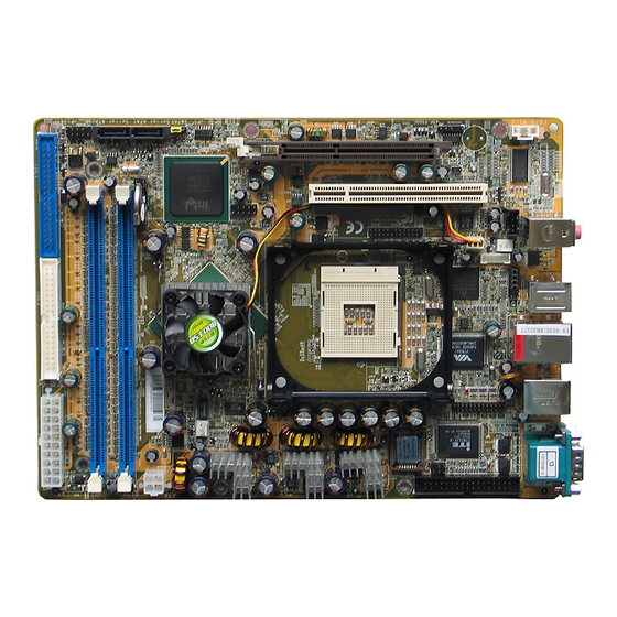
1.2 Item Checklist: Check all items with your FB75 mainboard to make sure nothing is missing. A complete package should include: - One Shuttle FB75 Mainboard AUDIO1 JP17 JP11 FAN1 USB1 FDD1 COM1 LAN1 USB2 SPDIF PCI1 FAN3 ALC650 AGP1... -
Page 11: Features
2 FEATURES FB75 mainboard is dedicatedly designed for demanding PC users who desire high perfor- mance and maximum intelligent features in a compact package. 2.1 Specifications - CPU Support Support Socket 478 package CPU. Intel Pentium 4 Processor with 533/800 MHz FSB. - Page 12 - I/O Interface Provides a variety of I/O interfaces: Ø 1 Floppy interface for 3.5-inch FDD with 720KB, 1.44MB, or 2.88MB format or for 5.25-inch FDD with 360K or 1.2MB format. Ø 2 x Serial ports Ø 1 x 1394a port Ø...
- Page 13 - Form Factor System board conforms to the Shuttle small form factor ATX specification. Board dimension: 254mm x 185mm. - Advanced Features Ø Low EMI - Built in spread spectrum. Unused PCI/SDRAM slots are shut off by the automatic clock for reducing EMI.
-
Page 14: Hardware Installation
This section outlines how to install and configure your mainboard. Referring to the follow- ing mainboard layout helps you identify various jumpers, connectors, slots, and ports. 3.1 Step-by-Step Installation (Accessories Of FB75) PS/2 Mouse & PS/2 Keyboard Port Connectors Giga LAN & USB Port Connectors Wireless KB/MS Header - JP6 IEEE1394a &... -
Page 15: Step 1 Cpu Installation
Step 1 CPU Installation: This mainboard supports Intel Pentium 4 Socket 478 series CPU. Please follow the steps as follows to finish CPU installation. Note the CPU orientation when you plug it into CPU socket. 1. Pull up the CPU socket lever to 90-degree angle. CPU socket lever up to 90-degree angle 2. -
Page 16: Step 2 Set Jumpers
Step 2. Set Jumpers The default jumper settings have been set for the common usage standard of this mainboard. Therefore, you need not to reset the jumpers unless you re- quire special adjustments as the following case: Clear CMOS Setting For first-time DIY system builders, we recommend that you not change the default jumper settings if you are not quite familiar with the mainboard con- figuration procedures. -
Page 17: Step 4 Install Internal Peripherals In System Case
Step 4 Install Internal Peripherals in System Case Before you place the mainboard into your system case, we recommend that you first assemble all the internal peripheral devices into the computer hous- ing, including, but not limited to, the hard disk drive (IDE/HDD), floppy disk drive (FDD), CD-ROM drive, and ATX power supply unit. -
Page 18: Step 5 Mount The Mainboard On The Computer Chassis
Step 5 Mount the Mainboard on the Computer Chassis 1. You may find there are a lot of mounting holes on your computer chassis and mainboard. To match the holes on both properly, the key point is to make the back panel of the mainboard in a close fit with your system case, as shown below. -
Page 19: Step 6 Connect Front Panel Leds/Switches/Usbs
Step 6 Connect Front Panel LEDs/Switches/USBs You can find there are several cables existing in the system case and originat- ing from the front panel devices (HDD LED, Green LED, Reset switch, and USB devices etc.). These cables serve to connect the front panel LEDs, switches, and USB connectors to JP13 and JP16/USB4, as shown below. -
Page 20: Step 7 Connect Ide, Serial Ata, And Floppy Disk Drives
Step 7 Connect IDE, Serial ATA, and Floppy Disk Drives 1. IDE cable connectors IDE2 IDE1 2. Serial ATA cable connectors SATA1 3. Floppy cable connector FDD1 - 16 -... -
Page 21: Step 8 Connect Other Internal Peripherals
Step 8 Connect Other Internal Peripherals 1. SPDIF in/out header (JP3) SPDIF 2. Front panel audio header (JP16); Audio CD_IN connector (JP11); Audio AUX_IN connector (JP17) JP11 JP17 JP16 3. Front panel 1394a header (JP16) JP16 - 17 -... - Page 22 4. Wireless KB/MS header (JP6) 5. Extended parallel port header (JP8) 6. IR header (JP7) - 18 -...
-
Page 23: Step 9 Connect The Power Supplies
Step 9 Connect the Power Supplies 1. System power connectors (ATX1/ATX2) ATX2 ATX1 Step 10 Install Add-On Cards in Expansion Slots 1. Accelerated Grapics Port (AGP) Card 2. PCI Card - 19 -... -
Page 24: Step 11 Connect External Peripherals To Back Panel
Step 11 Connect External Peripherals to Back Panel You are now ready to connect the external peripherals to your system's back panel. 1. Serial Ports 1/2 2. IEEE1394a Port 3. USB Ports 0/1/2/3 4. Giga LAN Port 5. PS/2 Mouse Port 6. -
Page 25: Step 12 System Boot Up For The First-Time
Step 12 System Boot Up For the First-Time To ensure your system completedly and correctly installed, please refer to the above installation steps once again before first booting up your system. 1. Insert a system-bootable floppy disk (DOS 6.2X, Windows 9X/NT, or others), which contains the FDISK and FORMAT utilities. -
Page 26: Step 13 Install Drivers & Software Components
2000/ME/NT/XP operating systems. Make sure your operating system is already installed before running the installation programs on CD-ROM. 1. Insert the FB75 bundled CD-ROM into your CD-ROM drive. The auto- run program will display the main installation window on screen. -
Page 27: Jumper Settings
3.2 Jumper Settings Several hardware settings are made through the use of mini jumpers to con- nect jumper pins on the mainboard. Pin #1could be located at any corner of jumpers, and the corner with a white right angle stands for Pin #1. There are several types of Pin #1 as shown below: 3-pin and multi-pin (>3) jumpers shown as follows: Pin #1 to the left:... -
Page 28: Jumpers & Connectors Guide
Jumpers & Connectors Guide Refer to the mainboard layout on page 10 and this section to help you iden- tify jumpers, slots, and connectors along with their assigned functions. B7~B9 B5~B6 B3~B4 B2~B3 C6~C8 C1~C4 CPU/Memory/Expansion Slots Socket 478 : CPU socket for Intel Pentium 4, 478-pin processors DIMM1/2 : Two DIMM slots for 64, 128, 256, 512 MB, and 1GB of 2.5V DDR SDRAM... -
Page 29: Jumpers
Jumpers : Clear CMOS setting Back Panel Connectors COM1/COM2 : Serial ports 1/2 1394a : IEEE1394a port : USB ports 0/1/2/3 GIGA LAN : Giga LAN port : PS/2 mouse port : PS/2 keyboard port CENTER/BASS : Center/Bass-Out port REAR-OUT : Rear-Out port LINE-OUT : Line-Out port... -
Page 30: Clear Cmos Setting (Jp1)
Jumpers Clear CMOS Setting (JP1) JP1 is used to clear CMOS data. Clearing CMOS will result in permanently erasing previous system configuration settings and the original factory-set system settings. Pin 1-2 (Normal)(Default) Pin 2-3 (Clear CMOS) Step 1. Turn off the system power (PC-->Off). Step 2. -
Page 31: Back Panel Connectors Com1/Com2 Port Connectors
Back Panel Connectors COM1/COM2 Port Connectors COM2 Port This mainboard can accommodate two serial devices on COM1/COM2. Attach serial device cables to the DB9 serial ports COM1/COM2 at the back panel of your computer. COM1 Port IEEE1394a Port Connector 1394a Port This mainboard offers one 1394a port on back panel. -
Page 32: Ps/2 Mouse & Ps/2 Keyboard Port Connectors
PS/2 Mouse & PS/2 Keyboard Port Connectors Two 6-pin female PS/2 Mouse & Key- board connectors are located on the PS/2 Mouse Port rear panel of the mainboard. In a desk- top computer, the PS/2 Mouse connec- tor is situated on the top of the PS/2 Key- board connector. -
Page 33: Front Panel Connectors Hdd Led Connector (Hled)
Front Panel Connectors HDD LED Connector (HLED) Attach a connector cable from the IDE device LED to the 2-pin (HLED) header. The HDD LED lights up whenever an IDE device is active. JP13 PWON GLED + HLED PWR_LED Note : Please notice all the LED connectors are directional. If your chassis's LED does not light up during running, please change it to the oppo- site direction. -
Page 34: Hardware Reset Connector (Rst)
Hardware Reset Connector (RST) Attach a cable to the 2-pin (RST) header. Pressing the reset switch causes the system to restart. JP13 PWON GLED + HLED PWR_LED ATX Power On/Off Switch Connector (PWON) The Power On/Off Switch is a momentary type switch used for turning on or off the ATX power supply. -
Page 35: Spdif In/Out Header (Jp3)
SPDIF In/Out Header (JP3) Port JP3 can be used to connect to a device with digital audio inputs/outputs. SPDIF Pin Assignments: 1=SPDIF-IN 2=GND 3=VCC 4=GND 5=VCC 6=SPDIF-OUT Front Panel Audio Header (JP16) This header allows users to install an auxiliary Front-Oriented Audio port for easier access. -
Page 36: Front Panel 1394A Header (Jp16)
Front Panel 1394a Header (JP16) The header is used to connect the cable attached to the 1394a connector which is mounted on front panel or back panel. But the 1394a cable is optional at the time of purchase. JP16 JP16 Pin Assignments: 9=TPA+ 10=TPA-... -
Page 37: Extended Usb Headers (Jp16/Usb4)
Extended USB Headers (JP16/USB4) Headers JP16/USB4 are used to connect cables to USB connectors mounted on front panel or back panel. The USB cable is optional at the time of pur- chase. JP16 USB4 JP16 Pin Assignments: 1=VCC 2=VCC 3=USB0- 4=USB1- 5=USB0+ 6=USB1+... -
Page 38: Internal Peripheral Connectors Enhanced Ide And Floppy Connectors (Ide1/Ide2 & Fdd1)
Internal Peripheral Connectors Enhanced IDE and Floppy Connectors (IDE1/IDE2 & FDD1) FB75 mainboard features two 40-pin dual-channel IDE device connectors (IDE1/IDE2), providing support up to four IDE devices, such as CD-ROM and Hard Disk Drive (HDD). This mainboard also includes one 34-pin floppy disk controller (FDC) to accommodate the Floppy Disk Drive (FDD). -
Page 39: Other Connectors Atx Power Supply Connectors (Atx1/Atx2)
Other Connectors ATX Power Supply Connectors (ATX1/ATX2) This motherboard uses 20-pin ATX power header (ATXPWR, ATX1), and comes with the other one header (ATX12V, ATX2). Please make sure you plug each in the right direction. It is essential to have these two power supply connectors plugged or your system won't boot up. -
Page 40: Cpu, System, And Chipset Fan Connectors (Fan1/2/3)
CPU, System, and Chipset Fan Connectors (FAN1/2/3) The mainboard provides three onboard 12V cooling fan power connectors to support the CPU (FAN1), system (FAN2), and chipset (FAN3). FAN1 Note: Both cable wiring and type of plug may vary, which depend on the fan maker. -
Page 41: Audio Aux_In Connector (Jp17)
Audio AUX_IN Connector (JP17) Port JP17 (White) can be used to connect stereo audio inputs from CD-ROM, TV-tuner or MPEG card. JP17 JP17 Pin Assignments: 1=AUXL 2=Ground 3=Cround 4=AUXR Wireless KB/MS Header (JP6) Port JP6 can be used to connect wireless keyboard and mouse devices. 11 9 7 5 3 1 1210... -
Page 42: Extended Parallel Port Header (Jp8)
Extended Parallel Port Header (JP8) One parallel port header is located at the rear panel of the mainboard. The header is used to connect the cable attached to a parallel connector. But the parallel cable and connector are optional at the time of purchase. IR Header (JP7) If you have an Infrared device, this mainboard can implement IR transfer function. -
Page 43: System Memory Configuration
3.3 System Memory Configuration The FB75 mainboard has two 184-pin DIMM slots that allow you to install from 64MB up to 2GB of system memory. Each 184-pin DIMM (Dual In-line Memory Module) slot can accommodate 64MB, 128MB, 256MB, 512MB, and 1GB of PC2700 or PC3200 compliant 2.5V single (1 Bank) or double (2 Bank) side 64-bit wide data path DDR SDRAM modules. -
Page 44: Software Utility
4 SOFTWARE UTILITY 4.1 Mainboard CD Overview Note: The CD contents attached in FB75 mainboard are subject to change without notice. To start your mainboard CD disc, just insert it into your CD-ROM drive and the CD AutoRun screen should appear. If the AutoRun screen does not appear, double click or run D:\Autorun.exe (assuming that your CD-ROM... -
Page 45: A Install Intel Chipset Driver
4.2.A Install Intel Chipset Driver Click on the "Install Mainboard Software"; then click on the "Install Intel Chipset Driver" bar to install the chipset driver. Once you made your selection, a Setup window will run the installation automatically. Reboot the system after the installation. -
Page 46: C Install Realtek Audio Driver
4.2.C Install Realtek Audio Driver Click on the "Install Mainboard Software"; then click on the "Install Realtek Audio Driver" bar to install the audio driver. Once you made your selection, a Setup window will run the installation automatically. Reboot the system after the installation. -
Page 47: Install Winflash Utility
4.4 View the User's Manual Click on the "Manual" bar, and on the sub-menu click on the "Install Acrobat Reader" bar if you need to install it, or click on the "Manual" bar to view the FB75 user's manual. - 43 -... -
Page 48: Bios Setup
5 BIOS SETUP FB75 BIOS ROM has a built-in Setup program that allows users to modify the basic system configuration. This information is stored in battery-backed RAM so that it retains the Setup information even if the system power is turned off. -
Page 49: The Main Menu
5.2 The Main Menu Once you enter the Award BIOS(tm) CMOS Setup Utility, the Main Menu will appear on the screen. The Main Menu allows you to select from several setup functions and two exit choices. Use the arrow keys to select among the items and press <Enter>... - Page 50 PnP/PCI Configurations This option configures how PnP (Plug and Play ) and PCI expansion cards operate in your system. PC Health Status This entry shows the current system temperature, voltage, and fan speed. Frequency/Voltage Control Use this menu to specify your settings for frequency/voltage control. Load Fail-Safe Defaults Use this menu to install fail-safe defaults for all appropriate items in the setup utility.
-
Page 51: Standard Cmos Features
Standard CMOS Features Use the arrow keys to highlight the item and then use the <PgUp> or <PgDn> keys to select the value you want in each item. Date (mm : dd : yy) Set the system date. Note that if you are running a Windows OS, this items are automatically updated whenever you make changes to the Windows Date. - Page 52 Base Memory/Extended Memory/Total Memory These items are automatically detected by the system at start up time. These are display-only fields. You can't make change to these fields. ****************************************************** IDE Adapters The IDE adapters control the hard disk drive. Use a separate sub-menu to configure each hard disk drive.
-
Page 53: Advanced Bios Features
Advanced BIOS Features This section allows you to configure your system for basic operation. Hard Disk Boot Priority This item lets you select hard disk boot device priority. BIOS Write Protect This item let you enable or disable the BIOS Write Protect. Ø... - Page 54 Hyper-Threading Technology The latest Intel application defines a high-speed calculating ability to optimize your system by two CPUs supported (one virtual, one physi- cal) in a multi-task environment. Ø The choice: Enabled or Disabled. Quick Power On Self Test Enable this item to shorten the power on testing (POST) and have your system start up faster.
- Page 55 Typematic Rate Setting If this item is enabled, you can use the following two items to see the typematic rate and the typematic delay settings for your keyboard. Ø The choice: Enabled or Disabled. Typematic Rate (Chars/Sec) This item sets how many times the keystroke will be repeated in a second when you hold a key down.
-
Page 56: Advanced Chipset Features
Advanced Chipset Features These items define critical timing parameters of the mainboard. You should leave the items at their default values unless you are very familiar with the technical, specifications of your system hardware. Changing values in- correctly may lead to fatal errors or recurring instability into your system. DRAM Timing Selectable The value in this field depends on performance parameters of the installed memory chips (DRAM). - Page 57 System BIOS Cacheable Selecting Enabled allows caching of the system BIOS ROM at F0000h~FFFFFh, resulting in better system performance. However, if any program is written to this memory area, a system error may result. Ø The Choice: Enabled or Disabled. Video BIOS Cacheable Selecting Enabled allows caching of the video BIOS, resulting in better system performance.
-
Page 58: Integrated Peripherals
Integrated Peripherals OnChip IDE Device Press <Enter> to enter the sub-menu of detailed options. IDE HDD Block Mode Block mode is also called block transfer, multiple commands, or mul- tiple sector read/write. If your IDE hard drive supports block mode (most new drivers do), select Enabled for automatic detection of the optimal number of block read/write per sector the drive can support. - Page 59 *** On-Chip Serial ATA Setting *** SATA Mode This item defines the serial ATA mode. Ø The Choice: IDE or RAID. On-Chip Serial ATA This item defines the onboard serial ATA. Ø The Choice: Disabled, Auto, Combined Mode, Enhanced Mode, or SATA Only.
- Page 60 SuperIO Device Press <Enter> to enter the sub-menu of detailed options. Onboard FDC Controller This item specifices onboard floppy disk drive controller. This setting allows you to connect your floppy disk drives to the onboard floppy connector. Ø The choice: Enabled or Disabled. Onboard Serial Port 1 This option is used to assign the I/O address and interrupt request (IRQ) for the onboard serial port 1 (COM1).
-
Page 61: Power Management Setup
Power Management Setup The Power Management Setup allows you to configure your system to most effectively saving energy while operating in a manner consistent with your own style of computer use. ACPI Function This item defines the ACPI (Advanced Configuration and Power Man- agement) feature that makes hardware status information available to the operating system, enables a PC to turn its peripherals on or off for improving the power management, and allows a PC turned on or off by... - Page 62 Power Management This item acts like a master switch for the power-saving modes and hard disk timeouts. If this item is set to Max Saving, power-saving modes occur after a short timeout. If it is set to Min Saving, power-saving modes occur after a longer timeout.
- Page 63 4 Sec., then you have to hold the power button down for 4 seconds to cause a software power down. Ø The choice: Delay 4 Sec. or Instant-Off. Wake-Up by PCI card This item leaves PCI cards wake up the system from the suspend mode. Ø...
- Page 64 FDD,COM,LPT Port When this item is enabled, the system will restart the power-saving timeout counters when any activity is detected on the floppy disk drive, the serial ports, or the parallel port. Ø The choice: Disabled or Enabled. PCI PIRQ[A-D]# When this item is disabled, any PCI device set as the Master will not power on the system.
-
Page 65: Pnp/Pci Configurations
PnP/PCI Configurations This category configures how PnP and PCI operate in your system. Correctly setting up the IRQ and DMA (both PnP and PCI use) assign- ments will make your system work stably. It is strongly recommended that only technical users make changes to the default settings. Reset Configuration Data When enabled, any PnP configuration data stored in the BIOS will be cleared from memory, with new data created. -
Page 66: Pc Health Status
PC Health Status CPU Fan Speed Control The item defines the fan speed control features. Ø The choice: Smart Fan, Ultra-Low, Low, Mid, or Full. This feature is controlled via BIOS, in which the CPU fan rotational speed sensing/control is governed by CPU temperature setting pre- selected in BIOS. - Page 67 Fan Speed Up When CPU Temp Enables 3 phase smart controls to the Selected fan. This feature ranges from 40 C to 80 C, in an increment of 4 Ø The choice: 40 C, 44 C, 48 C, 52 C, 56 C, 60 C, 64 C, 68...
-
Page 68: Frequency/Voltage Control
Frequency/Voltage Control CPU Clock Ratio This item allows you to adjust CPU ratio if your CPU clock ratio is unlocked. Auto Detect PCI Clk When this item is enabled, BIOS will disable the clock signal of free PCI slots. Ø The choice: Enabled or Disabled. Spread Spectrum This item defines the spread spectrum modulation. - Page 69 ****** Voltage ****** CPU Voltage set This item allows you to adjust CPU voltage. Ø The choice: Auto, 0.8250 V~1.5875 V. DDR Voltage set This item allows you to adjust DDR voltage. Ø The choice: Auto, 2.65 V, 2.70 V, or 2.75 V. AGP Voltage set This item allows you to adjust AGP voltage.
-
Page 70: Load Fail-Safe Defaults
Load Fail-Safe Defaults When you press <Enter> on this item, you will get a confirmation dialog box with a message similar to: Load Fail-Safe Defaults (Y/N) ? N Pressing 'Y' loads the BIOS default values for the most stable, minimal performance system operations. -
Page 71: Set Supervisor/User Password
Set Supervisor/User Password Steps to set supervisor/user password are described as follows: New Password Setting: 1. While pressing <Enter> to set a password, a dialog box appears to ask you enter a password. 2. Key in a new password. The password can not exceed eight charac- ters. -
Page 72: Save & Exit Setup
Save & Exit Setup Pressing <Enter> on this item asks for confirmation: SAVE to CMOS and EXIT (Y/N) ? Y Pressing "Y" stores the selections made in the menus of CMOS - a special section of memory that stays on after you turn your system off. The next time you boot your computer, the BIOS configures your system according to the Setup selections stored in CMOS.
Need help?
Do you have a question about the FB75 and is the answer not in the manual?
Questions and answers