Table of Contents
Advertisement
Quick Links
Advertisement
Table of Contents

Related Manuals for Shuttle FN95


Summary of Contents for Shuttle FN95
- Page 1 FN95 Socket 939 Athlon 64 Processor Based DDR Main Board User's Manual...
- Page 2 The information contained in this manual is provided for general use by the customers. Trademarks Shuttle is a registered trademark of Shuttle Inc. AMD Athlon 64 is registered trademarks of AMD Corporation. nVIDIA is a registered trademark of nVIDIA Corporation.
- Page 3 Statement of Shuttle Mainboard via the EMI Test Shuttle mainboards have been via the EMI test in terms of series of regulations: EN55022/ CISPR22/AS/NZS3548 Class B, EN55024 (1998/AS/NZS), EN4252.1 (1994), EN61000, ANSI C63.4 (1992), CFR47 Part 15 Subpart B, and CNS13438 (1997). The items tested are illus- trated as follows: (A) Voltage: AC 110V/60HZ &...
- Page 4 Crystal : 32.768 KHz(X2)/ 25 MHz(Y1)/ 25 MHz(X1)/ 24.576 MHz(X3)/ 24.576 MHz(X6) (D) Supported Host Peripherals: Host Peripheral Product Name Model Name FCC ID Case FN95 Power Supply (240W) PC35I2402 Western Digitel HDD WD300BB 3902B934 (30 GB) MITSUMI FDD D353M3D...
-
Page 5: Table Of Contents
2.1 SPECIFICATIONS ..................8 3 HARDWARE INSTALLATION ............11 3.1 STEP BY STEP INSTALLATION ..............11 Accessories of FN95 ................11 STEP 1 Install the CPU ................12 STEP 2 Set Jumper ................13 STEP 3 Install DDR SDRAM System Memory........13 STEP 4 Install Peripherals in System Case .......... - Page 6 STEP 13 Install Drivers & Software Components ........23 3.2 JUMPER SETTINGS ................. 24 JUMPERS & CONNECTORS GUIDE ............ 25 Jumper Clear CMOS Setting (JP17) ..............27 Back-Panel Connectors COM1 Port Connector ................28 SPDIF-IN Connector ................28 1394 Port Connector ................28 PS/2 Mouse &...
- Page 7 Other Connectors ATX Power Supply Connectors (ATX1/CN5) .......... 34 Fan Connectors - FAN1/2/3 OFF when suspend ........35 Wireless Keyboard/Mouse Connector (JP2) .......... 36 CD-IN Connector (CN7) (Black) ............. 36 LINE_IN Connector (CN8) (White) ............36 Mini CD_IN Connector (CN6) (White) ............ 36 Dual USB Header(JP3)/ USB Connectors(USB2, USB3).......
- Page 8 INTEGRATED PERIPHERALS ..............57 POWER MANAGEMENT SETUP .............. 60 PNP/PCI CONFIGURATION............... 63 PC HEALTH STATUS ................65 RATIO/VOLTAGE CONTROL ..............67 LOAD FAIL-SAFE DEFAULTS..............68 LOAD OPTIMIZED DEFAULTS ..............68 SET PASSWORD ..................68 SAVE & EXIT SETUP ................69 EXIT WITHOUT SAVING ................
-
Page 9: What's In The Manual
WHAT'S IN THE MANUAL Quick Reference Hardware Installation >> Step-by-Step ..........Page 11 Jumper Settings >> A Closer Look ............Page 24 Drivers/Software Utilities >> How to Install ......... Page 40 BIOS Setup >> How to Configure ............Page 44 About This Manual For First-Time DIY System Builder ............ -
Page 10: Introduction
Experienced DIY User Congratulate on your purchase of the Shuttle FN95 mainboard. You will find that installing your new Shuttle FN95 mainboard is just easy. Bundled with an array of onboard functions, the highly-integrated FN95 mainboard provides you with a total solution to build the most stable and reliable system. Refer to sections 3.2 Jumper Settings and Chapter 4 Drivers/Software Utilities to... -
Page 11: Item Checklist
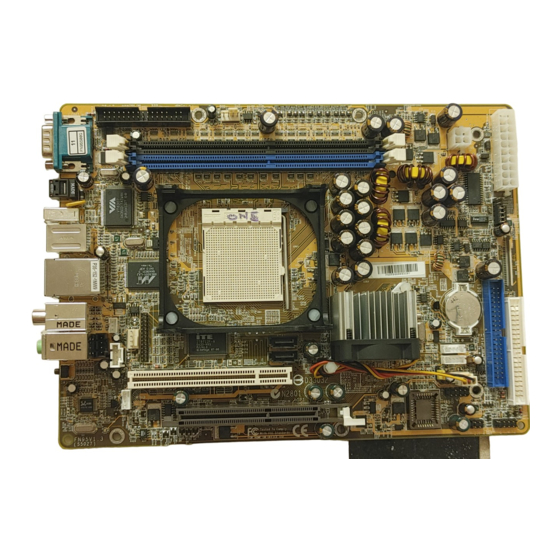
1.2 Item Checklist Check all items with you FN95 mainboard to make sure nothing is missing. The complete package should include: - One piece of Shuttle FN95 Mainboard DIMM1 DIMM2 FAN1 FAN2 JP17 USB3 USB2 IDE1 - One piece of ATA133/100/66/33 Ribbon Cable... -
Page 12: Features
2 FEATURES FN95 mainboard is carefully designed for the demanding PC user who wants high perfor- mance and maximum intelligent features in a compact package. 2.1 Specifications - CPU Support Athlon64 with 200MHz FSB colock on 939-pins SMT Socket. - Chipset nVIDIA nForce3 250 Ultra Single Chip for AMD Athlon64 939 CPU. - Page 13 Ø 2 x USB connectors on back-panel, one set of dual USB port header on mid- board. - I/O Interface Provides a variety of I/O interfaces: Ø 1 Floppy interface for 3.5-inch FDD with 720KB, 1.44MB, or 2.88MB format or for 5.25-inch FDD with 360K or 1.2MB format. Ø...
- Page 14 - System BIOS Provides licensed Award BIOS V6.0 PG on 4Mb Flash core and supports Green PC, Desktop Management Interface (DMI). - Form Factor System board conforms to Small form factor ATX specification. Board dimension: 254mm X185mm. - Advanced Features Ø...
-
Page 15: Hardware Installation
Then follow these steps designed to guide you through a quick and correct installation of your system. 3.1 Step-by-Step Installation Accessories Of FN95 10/100/1000LAN & Coaxial/Line-In Connectors 1.1/2.0 USB 2.0 Connectors... -
Page 16: Step 1 Install The Cpu
Step 1 Install the CPU: 1. Locate the CPU ZIF (Zero Insertion Force) socket on the upper-right sector of your mainboard (between the back-panel connectors and the DIMM memory slots). 2. Pull the CPU ZIF socket lever slightly sideways away from the socket to unlock the lever, and then bring it to an upwardly vertical position. -
Page 17: Step 2 Set Jumper
Step 2 Set Jumper This mainboard is jumperless! The default jumper settings have been set for the common usage standard of this mainboard. Therefore, you do not need to reset the jumpers unless you require special adjustments as any of the following cases: 1. -
Page 18: Step 4 Install Peripherals In System Case
Step 4 Install Internal Peripherals in System Case Before you install and connect the mainboard into your system case, we recommend that you first assemble all the internal peripheral devices into the computer housing, including but not limited to the hard disk drive (IDE/ HDD), floppy disk drive (FDD), CD-ROM drive, and ATX power supply unit. -
Page 19: Step 5 Mount The Mainboard On The Computer Chassis
Step 5 Mount the Mainboard on the Computer Chassis 1. You may find that there are a lot of different mounting hole positions both on your computer chassis and on the mainboard. To choose correct mounting holes, the key point is to keep the back-panel of the mainboard in a close fit with your system case, as shown below. -
Page 20: Connector(Jp16)
Step 6 Connect Front Panel Header You can find there are several different cables already existing in the system case and originatinting from the computer's front-panel devices (HDD LED, Power LED,or Reset Switch devices etc.) These cables serve to connect the front-panel switches and LEDs connectors to the mainboard's front-panel con- nectors group, as shown below. -
Page 21: Step 7 Connect Ide, Floppy And Serial Ata Drives
Step 7 Connect IDE, Floppy and Serial ATA Drives 1. IDE cable connectors IDE1 IDE2 2. Floppy cable connector 3. Serial ATA connectors ATA2 ATA1 - 17 -... -
Page 22: Step 8 Connect Other Internal Peripherals
Step 8 Connect Other Internal Peripherals 1. Wireless KB/MS Header (JP2) Wireless KB/MS 2. CD-IN(CN7), LINE-IN(CN8), MINI CD-IN(CN6) Connectors CD-IN Mini CD-IN LINE-IN CN8 3. IrDA Header (JP5) IrDA Header - 18 -... - Page 23 4. DUAL USB Header (JP3) USB Connectors (USB2/USB3) USB3 USB2 5. SPDIF out Connector (CN4) 6. Printer Port Connector (J1) - 19 -...
-
Page 24: Step 9 Install Add-On Cards In Expansion Slots
Step 9 Install Add-on Cards in Expansion Slots 1. Accelerated Graphics Port (AGP) Card AGP proof LED: Serving as a smart bur- nout protection for the motherboard, this red LED lights up if you plug in any 3.3V AGP card into the AGP slot. When this LED is Lit, there is no way you can turn AGP Proof on the system power even if you press... -
Page 25: Step 11 Connect External Peripherals To Back Panel
Step 11 Connect External Peripherals to Back-Panel You are now ready to put the computer case back together and get on to the external peripherals connections to your system's back-panel. 1. COM Port 2. SPDIF out Connector 3. 1394 Port 4. -
Page 26: Step 12 First Time System Boot Up
Step 12 First Time System Boot Up To assure the completeness and correctness of your system installation, you may check the above installation steps once again before you boot up your system for the first time. 1. Insert a bootable system floppy disk (DOS 6.2x, Windows 95/98/NT, or others) which contains FDISK and FORMAT utilities into the FDD. -
Page 27: Step 13 Install Drivers & Software Components
2000/ME/XP/NT operating systems only. Make sure your operating system is already installed before running the drivers installation CD-ROM programs. 1. Insert the FN95 bundled CD-ROM into your CD-ROM drive. The autorun program will display the drivers main installation window on screen. -
Page 28: Jumper Settings
3.2 Jumper Settings Several hardware settings are made through the use of mini jumpers to connect jumper pins on the mainboard. Pin #1 could be located at any corner of each jumper, you just find the location with a white right angle which stands for pin 1#. -
Page 29: Jumpers & Connectors Guide
Jumpers & Connectors Guide Use the mainboard layout on page 11 to locate CPU socket, memory banks, expansion slots, jumpers and connectors on the mainboard during the instal- lation. The following list will help you to identify jumpers, slots, and connec- tors along with their assigned functions: B10~B12 B8~B9... -
Page 30: Jumper
Jumper JP17 : Clear CMOS setting Back Panel Connectors COM1 : Serial port SPDIF IN : SPDIF IN Port 1394 : 1394 Port : PS/2 mouse port : PS/2 keyboard port : 10/100/1000 LAN port : 2 X USB (2.0/1.1) (Universal Serial Bus) ports Coaxial : Coaxial Output port Line-In... -
Page 31: Clear Cmos Setting (Jp17)
: MINI CD-IN connector JP3/USB2/USB3 : DUAL USB Header/ USB Connectors : IrDA Header : SPDIF Out Connector : Printer Port Connector Jumper Clear CMOS Setting (JP17) JP17 is used to clear CMOS data. Clearing CMOS will result in the perma- nently erasing previous system configuration settings and the restoring origi- nal (factory-set) system settings. -
Page 32: Back-Panel Connectors Com1 Port Connector
Back-Panel Connectors COM1 Port Connector This mainboard can accommodate one COM1 Port serial device on COM1. Attach a serial device cable to the DB9 serial port COM1 at the back-panel of your com- puter. SPDIF-IN Connector SPDIF IN connector can accept digital audio data from Optic fiber. -
Page 33: Coaxial Output Port Connector
Coaxial Output Port Coaxial Output Port Connector Coaxial Output connector can out- put digital audio data from coaxial cable. Line-In Port Connector Line-In is a stereo line-level input port that accepts a 1/8-inch TRS ste- reo plug. It can be used as a source for digital sound recording, a source to be mixed with the output, or both. -
Page 34: Front-Panel Connectors Atx Power On/Off Switch Connector (Pwon)
Front-Panel Connectors ATX Power On/Off Switch Connector (PWON) The Power On/Off Switch is a momentary type switch used for turning on or off the system ATX power supply. Attach the connector cable from the Power Switch to the 2-pin (PWON) header on the mainboard. Front Panel JP12 Note : Please notice all the LED connectors are directional. -
Page 35: Green Led/ Power Led Connector (Gled/Pwr_Led)
Green LED/ Power LED Connector (GLED/PWR_LED) This header is dual color LED function. Dual color LED function is defined by either Power LED or Green LED, the header can be in these states. The Green LED indicates that the system is currently in one of the power saving mode (Doze/Standby/Suspend). -
Page 36: Front Panel Audio/ Usb/ 1394 Connector (Jp16)
Front Panel AUDIO/ USB/ 1394 Connector (JP16) Port JP16 can be used to connect special device. Front Panel JP16 Pin Assignments: 1=USBVCC 3=USBVCC 2=USBVCC 4=USBVCC 6=USBVCC 5=USBVCC 7=USBVCC 9=USBA+ 8=USBVCC 10=USBA- 12=GND 11=GND 13=USBB+ 15=GND 14=USBB- 16=GND 18=TPA1- 17=TPA1+ 19=GND 21=TPB1+ 20=GND 22=TPB1-... -
Page 37: Internal Peripherals Connectors Enhanced Ide And Floppy Connectors
Internal Peripherals Connectors Enhanced IDE and Floppy Connectors The mainboard features two 40-pin dual-channel IDE device connectors (IDE1/ IDE2) providing support for up to four IDE devices, such as CD-ROM and Hard Disk Drives (H.D.D.). This mainboard also includes one 34-pin floppy disk con- troller (FDC) to accommodate the Floppy Disk Drive (FDD1). -
Page 38: Other Connectors Atx Power Supply Connectors (Atx1/Cn5)
Other Connectors ATX Power Supply Connectors (ATX1/CN5) This motherboard uses 20-pin ATX power header (ATX1), and comes with the other one header (CN5). Please make sure you plug each in the right direction. It is essential to have these two power supply connectors plugged or your sys- tem won't boot up. -
Page 39: Fan Connectors - Fan1/2/3 Off When Suspend
Fan Connectors - FAN1/2/3 OFF when suspend The mainboard provides three onboard 12V cooling fan power connectors to support FAN1, FAN2 or FAN3 cooling fans. FAN1 FAN_CTRL FAN_SENSE FAN2 POWER Ground FAN3 Note : Both cable wiring and type of plug may vary , which depends on the fan maker. -
Page 40: Wireless Keyboard/Mouse Connector (Jp2)
CD-IN Connector (CN7) (Black) Port CN7 is used to attach an audio connector cable from the CD-ROM drive. CD-IN 1 2 3 4 Pin Assignments: 1=CD-IN Left 2=Ground 3=Ground 4=CD-IN Right LINE_IN Connector (CN8) (White) Port CN8 (White) can be used to connect stereo audio inputs from CD-ROM, TV-tuner or MPEG card. -
Page 41: Dual Usb Header(Jp3)/ Usb Connectors(Usb2, Usb3)
Dual USB Header(JP3)/ USB Connectors(USB2, USB3) The headers are used to connect the cable attached to USB connectors which are mounted on front panel or back panel. But the USB cable is optional at the time of purchase. USB2/3 USB3 USB2 Pin Assignments (USB2/ USB3): Pin Assignments (JP3):... -
Page 42: Spdif Out Connector (Cn4)
SPDIF out Connector (CN4) Port CN4 can be used to connect a special device. 3 2 1 Pin Assignments: 1=SPDIF-OUT 2=VCC 3=GND E 1 0 Printer Port Connector (J1) One parallel port header is located at the rear panel of the mainboard. The header is used to connect the cable attached to a parallel connector. -
Page 43: System Memory Configuration
3.3 System Memory Configuration The FN95 mainboard has two 184-pin DIMM slots that allow you to install from 64MB up to 2GB of system memory. Each 184-pin DIMM (Dual In-line Memory Module) Slot can accommodate 64MB, 128MB, 256MB, 512MB, and 1GB of PC2100, PC2700 or PC3200 compliant 2.6V single or double side 64-... -
Page 44: Software Utility
Chipset, Marvell Giga LAN, nVIDIA USB 2.0 Driver. F Install Utility - Installing Acrobat Reader, Winflash Utility. F Manual - FN95 Manual and nVIDIA RAID User's Guide in PDF format. F Link to Shuttle Homepage - Link to shuttle website homepage. -
Page 45: A Install Directx9 Utility
4.2.A Install DirectX9 Utility Select using your pointing device (e.g. mouse) on the “Install DirectX9 Utility“ bar to install DirectX9. Once you made your se- lection, a Setup window run the installation automatically. When the copying files is done, make sure you reboot the system to take the installation effect. -
Page 46: C Install Marvell Giga Lan Driver
4.2.C Install Marvell Giga LAN Driver Select using your pointing device (e.g. mouse) on the "Install Marvell Giga LAN Driver" bar to install LAN driver. Once you made your se- lection, a Setup window run the installation automatically. When the copying files is done, make sure you reboot the system to take the installation... -
Page 47: View The User's Manual
1. Click on the “Install Acrobe Reader" bar if you need to install acrobe reader. 2. Click on "FN95 Manual" bar to view FN95 Series Mainboard User's Manual in PDF format. 3. Click on "nVIDIA RAID User's Guide" bar to view nVIDIA RAID User's Guide in PDF format. -
Page 48: Bios Setup
5 BIOS SETUP FN95 BIOS ROM has a built-in Setup program that allows users to modify the basic system configuration. This information is stored in battery-backed RAM so that it retains the Setup information even if the system power is turned off. -
Page 49: The Main Menu
5.2 The Main Menu Once you enter the AwardBIOS(tm) CMOS Setup Utility, the Main Menu will appear on the screen. The Main Menu allows you to select from several setup functions and two exit choices. Use the arrow keys to select among the items and press <Enter> to accept and enter the sub-menu. - Page 50 PnP / PCI Configurations This entry appears if your system supports PnP / PCI. PC Health Status This entry shows the current system temperature, Voltage, and FAN speed. Ratio/Voltage Control Use this menu to specify your settings for ratio control. Load Fail-Safe Defaults Use this menu to load the BIOS default values for the minimal/stable performance of your system to operate.
-
Page 51: Standard Cmos Features
Standard CMOS Features The items in Standard CMOS Setup Menu are divided into 10 catego- ries. Each category includes no, one or more than one setup items. Use the arrow keys to highlight the item and then use the <PgUp> or <PgDn>... - Page 52 Halt On Select the situation in which you want the BIOS to stop the POST process and notify you. Ø The choice: All Errors, No Errors, All, But Keyboard, All, But Diskette, or All, But Disk/Key. Base/Extended/Total Memory Theseitems are automatically detected by the system at start up time. These are display-only fields.
- Page 53 Cylinder Set the number of cylinders for this hard disk. Ø Min = 0, Max = 65535 Head Set the number of read/write heads. Ø Min = 0, Max = 255 Precomp Warning: Setting a value of 65535 means no hard disk. Ø...
-
Page 54: Advanced Bios Features
Advanced BIOS Features This section allows you to configure your system for basic operation. You have the opportunity to select the system's default speed, boot-up sequence, keyboard operation, shadowing, and security. Hard Disk Boot Priority This item allows you to select Hard Disk Book Device Priority. BIOS Write Protect The item allows you to enable/disable the Bios Write Protect. - Page 55 CPU Internal Cache All processors that can be installed in this mainboard use internal level 1 (L1) cache memory to improve performance. Leave this item at the default value for better performance. Ø The choice: Enabled or Disabled. External Cache Most processors that can be installed in this system use external level 2 (L2) cache memory to improve performance.
- Page 56 Typematic Rate Setting Keystrokes repeat at a rate determined by the keyboard controller. When this controller enabled, the typematic rate and typematic delay can be selected. Ø The choice: Enabled or Disabled. Typematic Rate (Chars/Sec) This item sets how many times the keystroke will be repented in a second when you hold the key down.
- Page 57 OS Select For DRAM > 64MB Selects the operating system that is running with greater than 64MB of RAM in the system. Ø The choice: Non-OS2 or OS2. Small Logo(EPA) Show This item allows you to enable/disable the EPA Logo. Ø...
-
Page 58: Advanced Chipset Features
Advanced Chipset Features This section allows you to configure the system based on the specific features of the installed chipset. This chipset manages bus speeds and access to sys- tem memory resources, such as DRAM and the external cache. It also coor- dinates communications between the conventional ISA bus and the PCI bus. - Page 59 RAS# to CAS# delay (tRCD) This field lets you insert a timing delay between the CAS and RAS strobesignals, and you can use it when DRAM is written to , read from, or refreshed. Faster performance is gained in high speed, more stable performance, in low speed..
- Page 60 AGP Sideband Address This item auto/disable the AGP sideband addressing capability for AGP cards. Ø The Choice: Auto or Disabled. Clock Spread Spectrum This item allows you to set the spread spectrum modulation. Ø The choice: Disabled or Enabled. HT Frequency This item allows you to set the HT Frequency.
-
Page 61: Integrated Peripherals
Integrated Peripherals Onboard IDE Device Options are in its sub-menu. Press <Enter> to enter the sub-menu of detailed options. RAID Function Setup This item allows you to setup the RAID Function. Ø The choice: Enter. OnChip IDE Channel0,1 The chipset contains a PCI IDE interface with support to two IDE chan- nels. - Page 62 Serial-ATA 2(Internal PHY) This item allows you to enable/disable the Serial-ATA 2(Internal PHY). Ø The choice: Enabled or Disabled. IDE DMA transfer access This item allows you to enable/disable the IDE DMA transfer access. Ø The choice: Enabled or Disabled. IDE HDD Block Mode Block mode is also called block transfer, multiple commands, or mul- tiple sector read/write.
- Page 63 connector. Ø The Choice: Enable or Disabled. Onboard Serial Port1 This option is used to assign the I/O address and interrupt request(IRQ) for the onboard serial port1(COM1). Ø The Choice: Disabled, 3F8-IRQ4, 2F8-IRQ3, 3E8-IRQ4, 2E8-IRQ3, or Auto. Onboard Infrared Port This option is used to assign the I/O address and interrupt request(IRQ) for the onboard infrared port.
-
Page 64: Power Management Setup
Power Management Setup The Power Management Setup allows you to configure your system to most effectively saving energy while operating in a manner consistent with your own style of computer use. ACPI Function This item allows Enable the Advanced Configuration and Power Man- agement (ACPI) Ø... - Page 65 Video Off Method This determines the manner in which the monitor is blanked. V/H SYNC+Blank This selection will cause the system to turn off the vertical and horizontal synchronization ports and write blanks to the video buffer. Blank Screen This option only writes blanks to the video buffer.
- Page 66 USB Resume From S3 If you are using a USB keyboard, and the ACPI suspend type is set to S3, you can enable this item to allow a keystroke to wake up the system from power saving mod. Ø The choice: Enabled, Disabled. Power-On by Alarm When set to Enabled, the following three fields become available and you can set the month, date (day of the month), hour, minute and...
-
Page 67: Pnp/Pci Configuration
PnP/PCI Configurations This section describes the configuration of PCI bus system. PCI or Personal Computer Interconnection is a system which allows I/O devices to operate at the speed CPU itself keeps when CPU communicating with its own special components. This section covers some very technical items, and it is strongly recommended that only experienced users should make any changes to the default settings. - Page 68 IRQ Resources When resources are controlled manually, assign each system interrupt a type, depending on the type of device using the interrupt. IRQ3/4/5/7/9/10/11/12/14/15 assigned This item allows you to determine the IRQ assigned to the ISA bus and is not available to any PCI slot. Legacy ISA for devices is compliant with the original PC AT bus specification;...
-
Page 69: Pc Health Status
PC Health Status CPU Fan Speed Control Set the CPU Fan Speed. Ø The choice: Smart Fan, Ultra-Low, Low , Mid , or Full . Note : Before manually modifying the CPU fan setting, please make sure fan connectors are plug into the correct fan connector designations on the mainboard. - Page 70 User Set CPU Fan Enabled you to choose one specific fan for further setting. Ø The choice: Fan1, Fan2, Fan3, Fan1 & Fan3. CPU Temp Tag Key in a DEC number. Min=30 Max=60 Ø The choice: 30~60 CPU Voltage AGP Voltage +3.3V VIN +5V VIN +12V VIN...
-
Page 71: Ratio/Voltage Control
Ratio/Voltage Control CPU Ratio Select This item allows you to set the CPU Ratio. Ø The choice: Auto, x4 800Mhz, x5 1000Mhz, x6 1200Mhz, x7 1400Mhz, x8 1600Mhz, x9 1800Mhz, x10 2000Mhz, x11 2200Mhz, x12 2400Mhz, x13 2600Mhz, x14 2800Mhz, x15 3000Mhz, x16 3200Mhz, x17 3400Mhz, x18 3600Mhz, x19 3800Mhz or x20 4000Mhz, CPU Voltage Select... -
Page 72: Load Fail-Safe Defaults
Load Fail-Safe Defaults When you press <Enter> on this item, you will get a confirmation dialog box with a message similar to: Load Fail-Safe Defaults (Y/N) ? N Pressing 'Y' loads the BIOS default values for the most stable, minimal performance system operations. -
Page 73: Save & Exit Setup
New Password Setting: 1. While pressing <Enter> to set a password, a dialog box appears to ask you enter a password. 2. Key in a new password. The password can not exceed eight charac- ters. 3. System will request you to confirm the new password again. 4.
Need help?
Do you have a question about the FN95 and is the answer not in the manual?
Questions and answers