Table of Contents
Advertisement
Quick Links
Advertisement
Table of Contents

Related Manuals for Shuttle FB86


Summary of Contents for Shuttle FB86
- Page 1 FB86 Intel Pentium 4 Desktop , LGA 775 Processor Based MAINBOARD...
- Page 2 The information contained in this manual is provided for general use by the customers. Trademarks Shuttle is a registered trademark of Shuttle Inc. Intel, Pentium is a registered trademarks of Intel Corporation. PS/2 is a registered trademark of IBM Corporation.
- Page 3 Statement of Shuttle Mainboard via the EMI Test Shuttle mainboards have been via the EMI test in terms of series of regulations: EN55022/ CISPR22/AS/NZS3548 Class B, EN55024 (1998/AS/NZS), EN4252.1 (1994), EN61000, ANSI C63.4 (1992), CFR47 Part 15 Subpart B, and CNS13438 (1997). The items tested are illus- trated as follows: (A) Voltage: AC 110V/60HZ &...
- Page 4 Remedy: N/A EMI Interference: Crystal : 14.318MHz(X2)/ 25MHz(X3)/ 32.768KHz(X1)/ 24.576MHz(X4) Clock Generator: U4 (D) Supported Host Peripherals: Host Peripheral Product Name Model Name Case FB86 Power Supply PC45I2753 Serial ATA Westerm Digital WD1200JD-00FYB0 Panasonic FDD JU-257A606P Pioneer DVD Player DVD-116 (E) Notices for Assembling Computers: 1.
- Page 5 Important Safety Information SAFETY INSTRUCTIONS 1. Please read these safety instructions carefully. 2. Please keep this User‘s Manual for later reference. 3. Please disconnect this equipment from AC outlet before cleaning. Don‘t use liquid or sprayed detergent for cleaning. 4. For pluggable equipment, the socket-outlet shall be installed near the equipment and shall be easily accessible.
-
Page 6: Table Of Contents
2.1 SPECIFICATIONS ..................8 3 HARDWARE INSTALLATION ............11 3.1 STEP BY STEP INSTALLATION ..............11 Accessories of FB86 ................11 STEP 1 CPU Installation ................ 12 STEP 2 Set Jumpers ................14 STEP 3 Install DDR SDRAM System Memory........14 STEP 4 Install Internal Peripherals in System Case ........ - Page 7 3.2 JUMPER SETTINGS ................. 24 JUMPERS & CONNECTORS GUIDE ............ 25 Back-Panel Connectors 1394a Port .................... 28 PS/2 Keyboard & PS/2 Mouse Ports ............. 28 Clear CMOS Button ................28 COM Port ....................28 VGA Port ....................28 Giga LAN Port ..................28 USB Ports .....................
- Page 8 CD-IN (CN3)(Black)/ Mini CD-IN (CN4) Connectors ....... 35 Wireless Keyboard and Mouse Connector (JP3)........35 EXT. Print Port (JP4) ................36 USB Header (USB1/USB3/JP2) ............37 EXT. GPI Header (JP1) ................37 3.3 SYSTEM MEMORY CONFIGURATION ............. 38 INSTALL MEMORY ................38 UPGRADE MEMORY ................
- Page 9 PNP/PCI CONFIGURATIONS ..............68 PC HEALTH STATUS ................70 FREQUENCY/VOLTAGE CONTROL ............. 72 LOAD FAIL-SAFE DEFAULTS .............. 74 LOAD OPTIMIZED DEFAULTS ............. 74 SET PASSWORD ................. 75 SAVE & EXIT SETUP................76 EXIT WITHOUT SAVING ................ 76 - 4 -...
-
Page 10: What's In The Manual
WHAT'S IN THE MANUAL Quick Reference Hardware Installation >> Step-by-Step ..........Page 11 Jumper Settings >> A Closer Look ............Page 24 Drivers/Software Utilities >> How to Install ......... Page 39 BIOS Setup >> How to Configure ............Page 46 About This Manual For First-Time DIY System Builder ............ -
Page 11: Introduction
Experienced DIY User Congratulate on your purchase of the Shuttle FB86 mainboard. You will find that installing your new Shuttle FB86 mainboard is just easy. Bundled with an array of onboard functions, the highly-integrated FB86 mainboard provides you with a total solution to build the most stable and reliable system. Refer to sec- tions 3.2 Jumper Settings and Chapter 4 Drivers/Software Utilities to... -
Page 12: Item Checklist
1.2 Item Checklist Check all items with your FB86 mainboard to make sure nothing is missing. The complete package should include: - One piece of Shuttle FB86 Mainboard ALC880 4 4 1 0 6 T 1 4 1 7 E... -
Page 13: Features
2 FEATURES FB86 mainboard is carefully designed for the demanding PC user who wants high perfor- mance and maximum intelligent features in a compact package. 2.1 Specifications - CPU Support Intel Pentium 4 Desktop Processors in the LGA 775 pin package with 533 / 800 MHz FSB. - Page 14 - USB 1.1/2.0 Complaint Interface Onboard Ø 4 UHCI host controller, 1 EHCI host controllers to support 8 USB 1.1/2.0 devices. All 8 USB ports can be assigned to USB 2.0 interface with BIOS option - I/O Interface Provides a variety of I/O interfaces: Ø...
- Page 15 - Advanced Configuration and Power Interface Features four power saving modes: S1 (Snoop), S3 (Suspend to RAM), S4 (Sus- pend to DISK), and S5 (Soft-Off). ACPI provides more efficient Energy Saving Features controlled by your operating system that supports OS Direct Power Management (OSPM) functionality.
-
Page 16: Hardware Installation
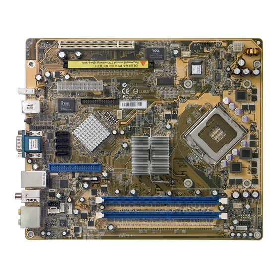
Then follow these steps designed to guide you through a quick and correct installation of your system. 3.1 Step-by-Step Installation Accessories Of FB86 COM/VGA Ports EXT.Print Port -JP4 One IDE Slot Serial ATA Ports- SATA1~4 Giga LAN(GbE)/USB 2.0/1.1 Ports... -
Page 17: Step 1 Cpu Installation
Step 1 CPU Installation: This mainboard supports Socket 775 Intel Pentium 4 Desktop processor (CPU). To install, follow the steps outlined below. Note the CPU orientation carefully when you insert it into the socket. Caution : This 775 pin socket is fragile and easily damaged. Always use extreme care when installing a CPU and limit the number of times that you remove or change the CPU. - Page 18 3. Orientate the CPU and socket, aligning the yellow triangle on the corner of the CPU with the triangle on the socket. Gently insert. Take care not to place any sideways force on the CPU when inserting, as the socket is fragile and easily damaged.
-
Page 19: Step 2 Set Jumpers
Step 2 Set Jumpers This mainboard is jumperless! The default jumper settings have been set for the common usage standard of this mainboard. Therefore, you do not need to reset the jumpers unless you require special adjustments as any of the following cases: 1. -
Page 20: Step 4 Install Internal Peripherals In System Case
Step 4 Install Internal Peripherals in System Case Before you install and connect the mainboard into your system case, we rec- ommend that you first assemble all the internal peripheral devices into the com- puter housing, including but not limited to the hard disk drive (IDE/HDD), floppy disk drive (FDD), CD-ROM drive, and ATX power supply unit. -
Page 21: Step 5 Mount The Mainboard On The Computer Chassis
Step 5 Mount the Mainboard on the Computer Chassis You may find that there are a lot of different mount- ing hole positions both on your computer chassis and on the mainboard. To choose correct mount- ing holes, the key point is to keep the backpanel of the mainboard in a close fit with your system case. -
Page 22: Step 7 Connect Ide, Floppy And Serial Ata Disk Drives
Step 7 Connect IDE, Floppy and Serial ATA Disk Drives 1. IDE cable connector IDE1 2. Floppy disk 3. Serial ATA connectors SATA1~4 - 17 -... -
Page 23: Step 8 Connect Other Internal Peripherals
Step 8 Connect Other Internal Peripherals 1. AUX-IN Connector (CN2)(White); CD-IN Connector (CN3)(Black); Mini CD-IN Connector (CN4) CD-IN AUX-IN Mini CD-IN 2. Wireless Keyboard/Mouse Select Header (JP3) Wireless KB/MS 3. EXT. Print Port Connector (JP4) EXT. Print Port - 18 -... - Page 24 4. USB Headers (USB1/USB3/ JP2) USB1 USB3 5. EXT.GPI Header (JP1) EXT. GPI Header - 19 -...
-
Page 25: Step 9 Install Add-On Cards In Expansion Slots
Step 9 Install Add-on Cards in Expansion Slots 1. PCI Card 2. PCI Express Graphics & SDVO Interface Card Step 10 Connect the Power Supply 1. System power connectors (ATX1/BTX1) BTX1 ATX1 - 20 -... -
Page 26: Step 11 Connect External Peripherals To Back-Panel
Step 11 Connect External Peripherals to Back-Panel You are now ready to put the computer case back together and get on to the external peripherals connections to your system's back-panel. 1. 1394a port 2. PS/2 Mouse port 3. PS/2 Keyboard port 4. -
Page 27: Step 12 First Time System Boot Up
Step 12 First Time System Boot Up To assure the completeness and correctness of your system installation, you may check the above installation steps once again before you boot up your system for the first time. 1. Insert a bootable system floppy disk (DOS 6.2x, Windows 95/98/NT, or others) which contains FDISK and FORMAT utilities into the FDD. -
Page 28: Step 13 Install Driver & Software Components
XP operating systems only. Make sure your operating system is already installed before running the drivers installation CD-ROM programs. 1. Insert the FB86 bundled CD-ROM into your CD-ROM drive. The autorun program will display the drivers main installation window on screen. -
Page 29: Jumper Settings
3.2 Jumper Settings Several hardware settings are made through the use of jumper caps to connect jumper pins to the mainboard. Pin #1 could be located at any corner of each jumper; you just find a location marked with a while right angle, which stands for pin1#. -
Page 30: Jumpers & Connectors Guide
Jumpers & Connectors Guide Use the mainboard layout on page 11 to locate CPU socket, memory banks, expansion slots, jumpers and connectors on the mainboard during the installa- tion. The following list will help you to identify jumpers, slots, and connectors along with their assigned functions: A4~A5 A6~A7... -
Page 31: Back-Panel Connectors
CPU/Memory/Expansion Slots LGA 775 : CPU Socket for Intel Pentium 4 Desktop processors DIMM1/2 : Two 184-pin DIMM Slots for 128 Mb, 256Mb, 512 Mb, and 1GB of 2.6V DDR SDRAM (The total installed memory does not exceed 4GB) : One 32-bit PCI Expansion Slot PCI-E : One 16-Lane PCI Express port for Graphic Attach Back Panel Connectors... - Page 32 Other Connectors ATX1/BTX1 : Power Connectors (4-pin ATX1, 24-pin BTX1) FAN1/2/3 : Fan Connectors : AUX-IN Connector CN3/CN4 : CD-IN/ Mini CD-IN Connectors : Wireless Keyboard and Mouse Select Header : EXT. Print Port USB1/USB3/JP2 : USB Headers : EXT. GPI Header - 27 -...
-
Page 33: 1394A Port
Back-Panel Connectors 1394a Port This mainboard offers one 1394a Port 1394a port on back-panel. Plug device jack into an avail- able 1394a port. PS/2 Keyboard & PS/2 Mouse Ports Two 6-pin female PS/2 PS/2 Keyboard & Mouse Ports keyboard & Mouse co- nnectors are located at the rear panel of the mainboard. -
Page 34: Usb Ports
USB Ports (0/1) USB Ports Two ports USB 0/1 share the same USB (Universal Serial Bus) bracket at the rear panel of your mainboard. Plug each USB device jack into an available USB 0/ USB1 port. SPDIF-Out Coaxial Port SPDIF-OUT Coaxial Port This mainboard can accom- modate one device on SPDIF-OUT Coaxial. -
Page 35: Spdif-In Optical Port
SPDIF-In Optical Port This mainboard can accommodate one device on SPDIF-IN Optical. Attach a SPDIF cable to the SPDIF-IN Optical Port at the back-panel of your computer. SPDIF-IN Optical Port 7.1 Channel Front-Out Port Front-Out is a stereo output port through which the com- bined signal of all internal and external audio sources on the Front-Out Port... -
Page 36: Front-Panel Connector
Front-Panel Connector FRONT PANEL Connector (JP7) Header JP7 is used to connect cable to front panel connector mounted on front-panel or back-panel. The front panel is where the hard drive activity lights,on/off button, computer power on light, USB connectors, 1394a connectors, and audio headers, are located. -
Page 37: Internal Peripherals Connectors
Internal Peripherals Connectors Enhanced IDE, Floppy Connectors The mainboard features one 40-pin dual-channel IDE device connectors (IDE1) providing support for up to two IDE devices, such as CD-ROM and Hard Disk Drives (H.D.D.). This mainboard also includes one 34-pin floppy disk control- ler (FDC) to accommodate the Floppy Disk Drive (FDD). -
Page 38: Other Connectors
Other Connectors ATX Power Supply Connectors (ATX1/BTX1) This mainboard uses 24-pin (BTX1) Pentium 4 standard ATX power header , ATX1 with 1X4-pin. Please make sure you plug in the right direction. BTX1 ATX1 BTX1 ATX1 Note 1: The ATX power connector is directional and will not go in unless the guides match perfectly making sure that pin#1 is properly positioned. -
Page 39: Fan Connectors- Fan1/2/3
Fan Connectors - FAN1/2/3 The mainboard provides three onboard 12V fan's power connectors to support cooling fans. FAN_SEN +12V Ground FAN_CTRL FAN3 FAN2 FAN1 Note : Both cable wiring and type of plug may vary , which depends on the fan maker. -
Page 40: Cd-In (Cn3)(Black)/ Mini Cd-In (Cn4) Connectors
CD-IN (CN3)(Black)/ Mini CD-IN (CN4) Connectors Port CN3 (Black) and CN4 are used to attach an audio connector cable from the CD-ROM drive. Pin Assignments (CN3): 1=CD-in Left CD-IN 2=CD-GND 3=CD-GND 4=CD-in Right Mini CD-IN Pin Assignments (CN4): 1=CD-GND 2=CD-in Right 3=CD-GND 4=CD-in Left Wireless Keyboard and Mouse Connector (JP3) -
Page 41: Ext. Print Port (Jp4)
EXT. Print Port (JP4) One DB25 male parallel port header is located at the rear panel of the maiboard. The header is used to connect the cable attached to parallel connector. But the parallel cable is optional at the time of purchase. EXT. -
Page 42: Usb Header (Usb1/Usb3/Jp2)
USB Headers (USB1/USB3/JP2) The headers are used to connect the cable attached to USB connectors which are mounted on front panel or back panel. But the USB cable is optional at the time of purchase. USB3 USB1 USB1 Pin Assignments (USB1/USB3): USB3 1=GND 2=GND... -
Page 43: System Memory Configuration
3.3 System Memory Configuration The FB86 mainboard has two 184-pin DIMM slots that allow you to install from 128MB up to 4GB of system memory. Each 184-pin DIMM (Dual In-line Memory Module) Slot can accommodate 128MB, 256MB, 512MB, 1GB, and 2GB of PC2700/PC3200 compliant 2.6V single (1 Bank) or double (2 Bank) side 64-bit wide data path DDR SDRAM modules. -
Page 44: Software Utility
4 SOFTWARE UTILITY 4.1 Mainboard CD Overview Note : The CD contents attached in FB86 mainboard are subject to change without notice. To start your mainboard CD disc, just insert it into your CD-ROM drive and the CD AutoRun screen should appear. If the AutoRun screen does not appear, double click or run D:\Autorun.exe (assuming that your CD-ROM drive is... -
Page 45: Install Mainboard Software
Insert the attached CD into your CD-ROM drive and the CD AutoRun screen should appear. If the AutoRun screen does not appear, double click on Autorun icon in My Computer to bring up Shuttle Mainboard Software Setup screen. Select using your pointing device (e.g. mouse) on the "Install Mainboard Software"... -
Page 46: A Install Intel Chipset Driver
4.2.A Install Intel Chipset Driver Select using your pointing device (e.g. mouse) on the "Install Intel Chipset Driver" bar to install Intel Chipset Driver. Once you made your se- lection, a Setup window run the installation automatically. When the copying files is done, make sure you reboot the system to take the installation... -
Page 47: C Install Intel Iaa Driver
4.2.C Install Intel IAA Driver Select using your pointing device (e.g. mouse) on the "Install Intel IAA Driver" bar to install IAA Driver. Once you made your se- lection, a Setup window run the installation automatically. When the copying files is done, make sure you reboot the system to take the installation... -
Page 48: E Install Intel Usb 2.0 Driver
4.2.E Install Intel USB 2.0 Driver Select using your pointing device (e.g. mouse) on the "Install Intel USB 2.0 Driver" bar to Giga LAN Driver. Once you made your selection, a Setup win- dow will run the installation automatically. Reboot the system after the installa- tion. -
Page 49: G Install Intel High Definition Audio Driver
4.2.G Install Intel High Definition Audio Driver Click on the "Install Mainboard Software"; then click on the "Install Intel High Definition Audio Driver" bar to install the High Definition Audio driver. Once you made your selection, a Setup window will run the installation auto- matically. -
Page 50: View The User's Manual
Insert the attached CD into your CD-ROM drive and the CD AutoRun screen should appear. If the AutoRun screen does not appear, double click on AutoRun icon in My Computer to bring up Shuttle Mainboard Software Setup screen. Select using your pointing device (e.g. mouse) on the "Manual" bar. -
Page 51: Bios Setup
5 BIOS SETUP FB86 BIOS ROM has a built-in Setup program that allows users to modify the basic system configuration. This information is stored in battery-backed RAM so that it retains the Setup information even if the system power is turned off. -
Page 52: The Main Menu
5.2 The Main Menu Once you enter the AwardBIOS(tm) CMOS Setup Utility, the Main Menu will appear on the screen. The Main Menu allows you to select from several setup functions and two exit choices. Use the arrow keys to select among the items and press <Enter> to accept and enter the sub-menu. - Page 53 PC Health Status This entry shows the current system temperature, Voltage, and FAN speed. Frequency/Voltage Control Use this menu to specify your settings for frequency/voltage control. Load Fail-Safe Defaults Use this menu to load the BIOS default values for the minimal/stable performance of your system to operate.
-
Page 54: Standard Cmos Features
Standard CMOS Features The items in Standard CMOS Setup Menu are divided into several categories. Each category includes no, one or more than one setup items. Use the arrow keys to highlight the item and then use the <PgUp> or <PgDn> keys to select the value you want in each item. Date <mm>... - Page 55 Halt On Select the situation in which you want the BIOS to stop the POST process and notify you. Ø The choice: All Errors, No Errors, All, But Keyboard, All, But Diskette, or All, But Disk/Key. Base Memory Displays the amount of conventional memory detected during boot up. Ø...
- Page 56 The following options are selectable only if the 'IDE Primary Master' item is set to 'Manual', and Access mode set to CHS. Cylinder Set the number of cylinders for this hard disk. Ø Min = 0, Max = 65535. Head Set the number of read/write heads.
-
Page 57: Advanced Bios Features
Advanced BIOS Features This section allows you to configure your system for basic operation. You have the opportunity to select the system's default speed, boot-up sequence, keyboard operation, shadowing, and security. CPU Feature Options are in its sub-menu. Press <Enter> to enter the sub-menu of detailed options. Delay Prior to Thermal This item is select Delay Prior to Thermal. - Page 58 TM2 Bus VID Represents the voltageof the throttled performance statethat will be initi- ated when the on diesensor gose from not hot to hot. Ø The Choice: 0.8375V ~1.6000V. Note: CPU supports TM2, item appear. Limit CPUID MaxVal Set Limit CPUID MaxVal to 3,Should Be "Disabled" for WinXp. Ø...
- Page 59 Ø The choice: Enabled or Disabled. CPU L1&L2&L3 Cache All processors that can be installed in this mainboard use internal level1(L1) , external 2(L2) and (L3) cache memory to imporve performance. Leave this item at the default value for better performance. Ø...
- Page 60 Ø The choice: Off or On. Gate A20 Option This entry allows you to select how the Gate A20 is handled. The gate A20 is a device used for above 1MByte of address memory. Initially, the gate A20 was handled via a pin on the keyboard. Today, while a key- board still provides this support, it is more common and much faster in setting to fast for the system chipset to provide support for gate A20.
- Page 61 APIC Mode Via the routing, I/O APIC support a total of 24 interrupts. Ø The choice: Always "Enabled". MPS Version Control For OS Selects the operating system multiprocessor support version. Ø The choice: 1.1 or 1.4. Delay For HDD <Secs> This item allows you to set delay for HDD<secs>.
-
Page 62: Advanced Chipset Features
Advanced Chipset Features This section allows you to configure the system based on the specific features of the installed chipset. This chipset manages bus speeds and access to system memory resources, such as DRAM and the external cache. It also coordinates communications between the conventional ISA bus and the PCI bus. - Page 63 ********** VGA Setting ********** PEG/Onchip VGA Control This item allows you to decide to activate whether PEG slot or Onchip VGA first. Ø The choice: Auto, Onchip VGA or PEG Port . PEG Force X1 This item allows you to force PEG link X1. Ø...
-
Page 64: Integrated Peripherals
Integrated Peripherals On-Chip IDE Device Option are in its sub-menu. Press<Enter>to enter the sub-menu of detailed options. IDE HDD Block Mode If your IDE hard disk drive supports block mode (most new drives do), select Enabled to automatic detect the optimal number of block read and writes per sector that the drive can support and improves the speed of access to IDE devices. - Page 65 IDE Primary Master/Slave UDMA Each IDE channel supports a master device and a slave device. This mainboard supports UltraDMA technology, which provides faster access to IDE devices. If you install a device that supports UltraDMA, change the appropriate item on this list to Auto. You may have to install the UltraDMA driver supplied with this mainboard in order to use an UltraDMA device.
- Page 66 Enhanced Mode:Enable both SATA and PATA. Max. of 4 ATA drives are supported. New OS that support switch to Enhanced mode (WinXP,Windows.NET Server,Windows2000 ) can set SATA and PATA to Enhanced Mode. Serial ATA SATA3 SATA4 SATA2 SATA1 Master (Channel 2) Master (Channel 3) Slave...
- Page 67 Onboard Device Option are in its sub-menu. Press<Enter>to enter the sub-menu of detailed options. USB Controller Select Enabled if your system contains a Universal Serial Bus (USB) port on this mainboard. Ø The choice: Enabled or Disabled. USB 2.0 Controller Select Enabled if your system contains a Universal Serial Bus (USB) 2.0 controller and you have USB peripherals.
- Page 68 Onboard Parallel Port This item allows you to determine onboard parallel port controller I/O address and interrupt request ( IRQ ). Ø The choice: 378/IRQ7, 278/IRQ5, 3BC/IRQ7 or Disabled. Parallel Port Mode Select an operating mode for the onboard parallel (printer) port. Select Normal, Compatible, or SPP unless you are certain your hardware and software both support one of the other available modes.
-
Page 69: Power Management Setup
Power Management Setup The Power Management Setup allows you to configure your system to most effectively saving energy while operating in a manner consistent with your own style of computer use. ACPI Function This item allows you to enable/disable the Advanced Configuration and Power Management (ACPI). - Page 70 Video Off Method This determines the manner in which the monitor is blanked. V/H SYNC+Blank This selection will cause the system to turn off the vertical and horizontal synchronization ports and write blanks to the video buffer. Blank Screen This option only writes blanks to the video buffer.
- Page 71 Ø The choice: Instant-Off or Delay 4 Sec. Wake-Up by PCI card This item Enabled/Disabled PCI Power Management Event to wake up system. Ø The choice: Enabled or Disabled. Power On by Ring This item determine the system will resume by activating of modem ring.
- Page 72 FDD, COM, LPT Port When this item is enabled, the system will restart the power-saving timeout counters when any activity is detected on the floppy disk drive, serial ports, or the parallel port. Ø The choice: Disabled or Enabled. PCI PIRQ [A-D] # When this item is disabled, any PCI device set as the Master will not power on the system.
-
Page 73: Pnp/Pci Configurations
PnP/PCI Configurations This section describes the configuration of PCI bus system. PCI or Per- sonal Computer Interconnection is a system which allows I/O devices to operate at the speed CPU itself keeps when CPU communicating with its own special components. This section covers some very technical items, and it is strongly recom- mended that only experienced users should make any changes to the default settings. - Page 74 If you set this field to "manual" , choose specific resources by going into each of the sub-menu that follows this field (a sub-menu is proceeded by a ">"). Ø The choice: Auto(ESCD) or Manual. IRQ Resources When resources are controlled manually, assign each system interrupt a type, depending on the type of device using the interrupt.
-
Page 75: Pc Health Status
PC Health Status Advanced CPU Fan Setting Set the CPU Fan Speed. ØThe choice : Smart Fan Mode, Ultra- Low Fan Speed, Low Fan Speed, Mid Fan Speed or Full Fan Speed. Smart Fan Mode : Keep FAN speed as low as possible, and maintain CPU temp not over setting in the same time automatically. - Page 76 LED Bright Setting The item allows you to set the LED bright. Ø The choice: 0%, 25%, 37.5%, 50%, 62.5%, 75%, 87.5% or 100% CPU Voltage Chipset Voltage +3.3V +12V -12V DDR Voltage +5VSB Voltage Battery CPU Temperature System Temperature CPU Fan Speed Fan 2 Speed Fan 3 Speed...
-
Page 77: Frequency/Voltage Control
Frequency/Voltage Control Auto Detect PCI Clk This item allows you to enable/disable auto disable empty PCI Slot Clock. Ø The choice: Enabled or Disabled. Spread Spectrum This item allows you to enable or disable the spread spectrum modula- tion. Ø The choice: Enabled or Disabled. DRAM Timing Selectable The value in this field depends on performance parameters of the installed memory chips(DRAM). - Page 78 Ø The Choice: 2, 3, 4, 5 or Auto. DRAM RAS# Precharge If an insufficient number of cycles is allowed for the RAS to accumulate its charge before DRAM refresh, the refresh may be-incompleted, and the DRAM may fail to retain data. Fast gives faster performance; and Slow gives more stable performance.
-
Page 79: Load Fail-Safe Defaults
PCIEX CLK This item allows the user to adjust PCIEX CLK. Ø The Choice: Sync by CPU Clock or Fixed 100 MHz. ********** Voltage ********** CPU Voltage set This item allows you to set the CPU & AGP/PCI Clock Set. The choice: Auto, 0.8250V~1.5875 V. -
Page 80: Set Password
Set Password This item is to set supervisor password. Please follow below steps. New Password Setting : 1. While pressing <Enter> key to start setting password function, a dialog box appears to ask you “Enter password: “. 2. Key in a new password now. However, the password can not be over eight characters or numbers. -
Page 81: Save & Exit Setup
Save & Exit Setup Pressing <Enter> on this item asks for confirmation: Save to CMOS and EXIT (Y/N)? Y Pressing "Y" stores the selections made in the menus of CMOS - a special section of memory that stays on after you turn your system off. The next time you boot your computer, the BIOS configures your system according to the Setup selections stored in CMOS.
Need help?
Do you have a question about the FB86 and is the answer not in the manual?
Questions and answers