Table of Contents
Advertisement
Quick Links
Advertisement
Table of Contents

Related Manuals for Shuttle FS51


Summary of Contents for Shuttle FS51
- Page 1 FS51 Pentium 4 / Celeron , 478-pin Processor Based DDR MAIN BOARD User's Manual...
- Page 2 The information contained in this manual is provided for general use by the customers. Trademarks Shuttle is a registered trademark of Shuttle Inc. Intel, Pentium is a registered trademark of Intel Corporation. SIS is a registered trademark of SIS Corporation.
-
Page 3: Table Of Contents
2.1 SPECIFICATIONS ..................8 3 HARDWARE INSTALLATION ............11 3.1 STEP BY STEP INSTALLATION ..............11 Accessories of FS51 ................11 STEP 1 CPU Installation ................ 12 STEP 2 Set Jumpers ................14 STEP 3 Install DDR SDRAM System Memory........14 STEP 4 Install Internal Peripherals in System Case ........ - Page 4 3.2 JUMPER SETTINGS ................. 23 JUMPERS & CONNECTORS GUIDE ............ 24 Jumpers Clear CMOS Setting (JP1) ..............27 Back-Panel Connectors COM1/2 Port Connectors ..............28 VGA Port Connector ................28 IEEE 1394 Port Connectors ..............28 10/100 base-T LAN Port Connector ............28 USB0/1 Port Connectors ...............
-
Page 5: Bios Setup
CPU and System Fan Connector - FAN1/2/3) ........37 Audio CD_IN Connector (CN3) (Black) ..........37 Wireless Keyboard and Mouse Connectors (JP2) ........38 SPDIF Ext/In/Out Headers (JP9) ............38 3.3 SYSTEM MEMORY CONFIGURATION ............. 39 INSTALL MEMORY ................39 UPGRADE MEMORY ................ - Page 6 LOAD FAIL-SAFE DEFAULTS ..............73 LOAD OPTIMIZED DEFAULTS ..............73 SET PASSWORD ..................74 SAVE & EXIT SETUP ................74 EXIT WITHOUT SAVING ................75 - 4 -...
-
Page 7: What's In The Manual
WHAT'S IN THE MANUAL Quick Reference Hardware Installation >> Step-by-Step ..........Page 11 Jumper Settings >> A Closer Look ............Page 23 Drivers/Software Utilities >> How to Install ......... Page 40 BIOS Setup >> How to Configure ............Page 49 About This Manual For First-Time DIY System Builder ............ -
Page 8: Introduction
3.1 Hardware installation, a step-by-step fashion for all the first time DIY system builder was designed. Prior to installation, we also suggest you to read the whole manual carefully to gain a complete understanding of your new FS51 mainboard. Experienced DIY User You will find that installing your new FS51 mainboard is easy. -
Page 9: Item Checklist
- One piece of twin ports USB Cable (optional) - FS51 User's Manual - One piece of Bundled CD-ROM containing: Ø FS51 user's manual saved in PDF format Ø SiS Chipset driver Ø Realtek Audio driver Ø SiS VGA driver Ø... -
Page 10: Features
2 FEATURES FS51 mainboard is carefully designed for the demanding PC user who wants high perfor- mance and maximum intelligent features in a compact package. 2.1 Specifications - CPU Support Intel Pentium 4 / Celeron, 478-pin processors with 400/533 MHz FSB. - Page 11 - I/O Interface Provides a variety of I/O interfaces: Ø 1 x Floppy interface for 3.5-inch FDD with 720KB, 1.44MB, or 2.88MB format . Ø 2 x DB9 Serial connectors 16550 UART compatible. Ø 1 x DB15 VGA connector. Ø 1 x SPDIF-In port. Ø...
-
Page 12: System Bios
- System BIOS Provides licensed Award BIOS V6.0 PG on 2Mb Flash core and supports Green PC, Desktop Management Interface (DMI). - Form Factor System board conforms to form factor ATX specification. Board dimension: 254mm x 185mm. - Advanced Features Ø... -
Page 13: Hardware Installation
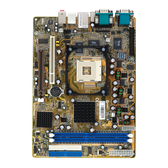
Then follow these steps designed to guide you through a quick and correct installation of your system. 3.1 Step-by-Step Installation Accessories Of FS51 1394 Connectors COM2 Connectors LAN & USB 2.0/1.1 Connectors... -
Page 14: Step 1 Cpu Installation
Step 1 CPU Installation: This mainboard supports Intel Pentium 4 /Celeron, Socket 478 series CPU. ® ® Please follow the steps below to finish CPU installation. Be careful of CPU orientation when you plug it into CPU socket. 1. Pull up the CPU socket lever up to 90-degree angle. CPU socket lever up to 90 degree 2. - Page 15 3. Press down the CPU socket lever and finish CPU installation. Note: If you do not match the CPU socket Pin 1 and CPU cut edge well, it may damage the CPU. 4. The Intel Pentium 4 /Celeron processor requires a set of heatsink/fan to en sure proper cooling of the processor.
-
Page 16: Step 2 Set Jumpers
Step 2. Set Jumpers This mainboard is jumperless! The default jumper settings have been set for the common usage standard of this mainboard. Therefore, you do not need to reset the jumpers unless you require to clear the CMOS. For first-time DIY system builders, we recommend that you do not change the default jumper settings if you are not totally familiar with the mainboard configuration procedures. -
Page 17: Step 4 Install Internal Peripherals In System Case
Step 4 Install Internal Peripherals in System Case Before you install and connect the mainboard into your system case, we recommend that you first assemble all the internal peripheral devices into the computer housing, including but not limited to the hard disk drive (IDE/ HDD), floppy disk drive (FDD), CD-ROM drive, and ATX power supply unit. -
Page 18: Step 5 Mount The Mainboard On The Computer Chassis
Step 5 Mount the Mainboard on the Computer Chassis 1. You may find that there are a lot of different mounting hole positions both on your computer chassis and on the mainboard. To choose the correct mounting holes, keep the back-panel of the mainboard in a close fit with your system case. -
Page 19: Step 6 Connect Front Panel Switches/Leds/Speaker/Usb
Step 6 Connect Front Panel Switches/LEDs/Speaker/USB You can find there are several different cables already existing in the system case and originating from the computer's front-panel devices (HDD LED, Power LED, Reset Switch, or USB devices etc.) These cables serve to connect the front-panel switches, LEDs, and USB connectors to the mainboard's front- panel connectors group (JP3, JP8, JP10), as shown below. -
Page 20: Step 7 Connect Ide And Floppy Disk Drives
Step 7 Connect IDE and Floppy Disk Drives 1. IDE cable connectors IDE2 IDE1 2. Floppy cable connector Step 8 Connect Other Internal Peripherals 1. CD-IN (CN3), Microphone CD-IN and Line-Out (JP4) connectors 2. 1394 header (JP5) 1394 - 18 -... -
Page 21: Step 9 Connect The Power Supply
3. Wireless keyboard and mouse headers (JP2) Step 9 Connect the Power Supply 1. System power connector ATXPWR Step 10 Install Add-on Cards in Expansion Slots 1. Accelerated Graphics Port (AGP) Card 1. PCI Card - 19 -... -
Page 22: Step 11 Connect External Peripherals To Back-Panel
Step 11 Connect External Peripherals to Back-Panel You are now ready to put the computer case back together and proceed to the external peripherals connections to your system's back-panel. COM1 Port COM2 Port VGA Port SPDIF In Port 1394 Ports LAN Port USB0/1 Ports PS/2 Mouse... -
Page 23: Step 12 First Time System Boot Up
Step 12 First Time System Boot Up To assure the completeness and correctness of your system installation, you may check the above installation steps once again before you boot up your system for the first time. 1. Insert a bootable system floppy disk (DOS 6.2x, Windows 95/98/NT, or others) which contains FDISK and FORMAT utilities into the FDD. -
Page 24: Step 13 Install Drivers & Software Components
2000/ME/XP/NT operating systems only. Make sure your operating system is already installed before running the drivers installation CD-ROM programs. 1. Insert the FS51 bundled CD-ROM into your CD-ROM drive. The autorun program will display the drivers main installation window on screen. -
Page 25: Jumper Settings
3.2 Jumper Settings Several hardware settings are made through the use of mini jumpers to con- nect jumper pins on the mainboard. Pin #1 could be located at any corner of each jumper, you just find the location with a white right angle which stands for pin 1#. -
Page 26: Jumpers & Connectors Guide
Jumpers & Connectors Guide Use the mainboard layout on page 11 to locate CPU socket, memory banks, expansion slots, jumpers and connectors on the mainboard during the instal- lation. The following list will help you to identify jumpers, slots, and connec- tors along with their assigned functions: B4~B6 B8~B10... -
Page 27: Jumpers
: Two 32-bit PCI Expansion Slot Jumpers : Clear CMOS setting Back Panel Connectors COM1/2 : Serial port 1/2 (DB9 male) : VGA port (DB15 female) 1394 : 2 x 1394 (0/1) Ports : 10/100 base-T LAN Port : 2 USB 2.0/1.1 (0/1) (Universal Serial Bus) ports : PS/2 mouse port : PS/2 keyboard port BASS/CENTER... - Page 28 FAN3 : CPU fan connector : Audio CD_IN connector : Wireless Keyboard and Mouse connector : SPDIF Ext/In/Out connectors - 26 -...
-
Page 29: Clear Cmos Setting (Jp1)
Jumpers Clear CMOS Setting (JP1) JP1 is used to clear CMOS data. Clearing CMOS will result in the perma- nently erasing previous system configuration settings and the restoring origi- nal (factory-set) system settings. Pin 1-2 (Default) Pin 2-3 (Clear CMOS) Step 1. -
Page 30: Back-Panel Connectors
Back-Panel Connectors COM1/2 Port Connectors COM1 Port COM2 Port This mainboard can accommodate one serial device on COM1/2. Attach a serial device cable to the DB9 serial port COM1/2 at the back- panel of your computer. VGA Connector One 15-pin VGA connector is located at the rear panel of the mainboard. -
Page 31: Usb0/1 Port Connectors
USB Port 0/1 Connectors USB Port 1 Two female connectors USB0/USB1 share the same USB (Universal Serial Bus) bracket at the rear panel of your mainboard. Plug each USB device jack into an available USB0/USB1 connec- USB Port 0 tor. PS/2 Keyboard &... -
Page 32: Line-In (Rear-Out) Port Connector
Line-In (Rear-Out) Port Connector Line-In is a stereo line-level input port that accepts a 1/8-inch TRS stereo plug. It can be used as a source for digital sound recording, a source to be mixed with the output, or both. Line-In Port (Rear-Out) SPDIF In Port SPDIF In connector can accept digital audio data from Optic fiber. -
Page 33: Front-Panel Connectors Atx Power On/Off Switch Connector (Pwon)
Front-Panel Connectors ATX Power On/Off Switch Connector (PWON) The Power On/Off Switch is a momentary type switch used for turning on or off the system ATX power supply. Attach the connector cable from the Power Switch to the 2-pin (PWON) header on the mainboard. Note : Please note that all the LED connectors are directional. -
Page 34: Green Led / Power Led Connector (Gled/Pled)
Green LED / Power LED Connector (GLED/PLED) This header is dual color LED function. Dual color LED function is defined by either Power LED or Green LED, the header can be in these states. The Green LED indicates that the system is currently in one of the power saving mode (Doze/Standby/Suspend). -
Page 35: Extended Usb Headers (Jp3/Jp10)
Extended USB Header (JP3/JP10) The headers are used to connect the cable attached to USB connectors which are mounted on front panel or back panel. The USB cable is optional at the time of purchase. port port Pins Assignment: 1=+5V 3=USBD0- 5=USBD0+ 7=GND... -
Page 36: Parallel Port Header (Jp11)
Parallel Port Header (JP11) One DB25 male parallel port header is located at the rear panel of the mainboard. The header is used to connect the cable attached to parallel con- nector. The parallel cable and connector are optional at the time of purchase. Front-Panel Microphone and Line_out Header (JP4) This header allows users to install auxiliary front-oriented microphone and line- out ports for easier access. -
Page 37: Internal Peripherals Connectors
Internal Peripherals Connectors Enhanced IDE and Floppy Connectors The mainboard features two 40-pin dual-channel IDE device connectors which (IDE1/IDE2) provide support for up to four IDE devices, such as CD- ROM and Hard Disk Drives (H.D.D.). This mainboard also includes one 34-pin floppy disk controller (FDC) to accommodate the Floppy Disk Drive (FDD). -
Page 38: Other Connectors
Other Connectors ATX Power Supply Connectors (CN5 and JP7) This motherboard uses 20-pin (CN5) Pentium 4 standard ATX power header, and JP7 with 1X4-pin +12V PC ATX power supply headers. Please make sure you plug in the right direction. P3/P4 ATX Power supply headers ATXPWR Note This motherboard can't support AC power resumes from... -
Page 39: Cpu And System Fan Connector - Fan1/2/3)
CPU and System Fan Connectors - FAN1/2/3 The mainboard provides three onboard 12V cooling fan power connectors to support System (FAN1), Chipset (FAN2), or CPU (FAN3) cooling fans. +12V SENSE FAN3 FAN1/2/3 with rotate sense. Note: Both cable wiring and type of plug may vary , depending on the fan manufacturer. -
Page 40: Wireless Keyboard And Mouse Connectors (Jp2)
Wireless Keyboard and Mouse Connector (JP2) Port JP2 can be used to connect wireless keyboard and mouse device. 2 4 6 8 1 3 5 7 Pin Assignments: 1=+5V 2=KEY 3=MS-DT 4=KB-DT 5=MS-CK 6=KB-CK 7=GND 8=GND SPDIF Ext/In/Out Headers (JP9) Port JP9 can be used to connect special device. -
Page 41: System Memory Configuration
3.3 System Memory Configuration The FS51 mainboard has two 184-pin DIMM slots that allow you to install from 64MB up to 2GB of system memory. Each 184-pin DIMM (Dual In-line Memory Module) Slot can accommodate 64MB, 128MB, 256MB, 512MB, and 1GB of PC1600/PC2100/PC2700 compliant 2.5V single (1 Bank) or double (2 Bank) side 64-bit wide data path... -
Page 42: Software Utility
4 SOFTWARE UTILITY 4.1 Mainboard CD Overview Note: The CD contents attached in FS51 mainboard are subject to change without notice. To start your mainboard CD disc, just insert it into your CD-ROM drive and the CD AutoRun screen should appear. If the AutoRun screen does not appear, double click or run D:\Autorun.exe (assuming that your CD-ROM... -
Page 43: Install Sis Vga Driver
4.2 Install SIS VGA Driver Insert the attached CD into your CD-ROM drive and the CD AutoRun screen should appear. If the AutoRun screen does not appear, double click on Autorun icon in My Computer to run Mainboard Software Setup. Select using your pointing device (e.g. -
Page 44: Install Sis Agp Driver
4.3 Install SIS AGP Driver Insert the attached CD into your CD-ROM drive and the CD AutoRun screen should appear. If the AutoRun screen does not appear, double click on Autorun icon in My Computer to run Mainboard Software Setup. Select using your pointing device (e.g. -
Page 45: Install Audio Driver
4.4 Install Audio Driver Insert the attached CD into your CD-ROM drive and the CD AutoRun screen should appear. If the AutoRun screen does not appear, double click on Autorun icon in My Computer to run Mainboard Software Setup. Select using your pointing device (e.g. mouse) on the “Install Audio De- vice Driver"... -
Page 46: Install Lan Driver
4.5 Install LAN Driver Insert the attached CD into your CD-ROM drive and the CD AutoRun screen should appear. If the AutoRun screen does not appear, double click on Autorun icon in My Computer to run Mainboard Software Setup. Select using your pointing device (e.g. mouse) on the “Install LAN Driver” bar to install LAN driver. - Page 47 Then PCI Ethernet Controller Prop- erties windows will appear on your screen. Click on the "Reinstall Driver" bar to install driver. The Update Device Driver Wizard windows will appear on your screen. Click on "Next" bar to continue. Please choose "Display a list of the drivers"...
- Page 48 Insert the support CD by the mainboard manufacturer and choose "Have Disk" bar to continue next step. Indicate the driver's location as "D:\lan\WIN98\NETRTS5.INF" (Assuming CD-ROM drive is Drive D:) Select "Realtek RTL8139/810X Family PCI Fast Ethernet NIC" to install, and then click "OK". Make sure "Realtek RTL8139/810X Family PCI Fast Ethernet NIC"...
-
Page 49: Install Usb 2.0 Driver
After restart, you may check Network adapters under the location. Shown in the figure on the right. 4.6 Install USB 2.0 Driver Select using your pointing device (e.g. mouse) on the "Install USB 2.0 Driver" bar to install audio driver. Once you made your selection, a Setup window will run the installation automatically. -
Page 50: View The User's Manual
4.7 View the User's Manual Insert the attached CD into your CD-ROM drive and the CD AutoRun screen should appear. If the AutoRun screen does not appear, double click on AutoRun icon in My Computer to run Mainboard Software Setup . Select using your pointing device (e.g. -
Page 51: Bios Setup
5 BIOS SETUP FS51 BIOS ROM has a built-in Setup program that allows users to modify the basic system configuration. This information is stored in battery-backed RAM so that it retains the Setup information even if the system power is turned off. -
Page 52: The Main Menu
5.2 The Main Menu Once you enter the AwardBIOS(tm) CMOS Setup Utility, the Main Menu will appear on the screen. The Main Menu allows you to select from several setup functions and two exit choices. Use the arrow keys to select among the items and press <Enter> to accept and enter the sub-menu. - Page 53 PnP / PCI Configurations This entry appears if your system supports PnP / PCI. PC Health Status This entry shows the current system temperature, Voltage, and FAN speed. Frequency/Voltage Control Use this menu to specify your settings for frequency/voltage control. Load Fail-Safe Defaults Use this menu to load the BIOS default values for the minimal/stable performance of your system to operate.
-
Page 54: Standard Cmos Features
Standard CMOS Features The items in Standard CMOS Setup Menu are divided into several categories. Each category includes no, one or more than one setup items. Use the arrow keys to highlight the item and then use the <PgUp> or <PgDn> keys to select the value you want in each item. Date Date Date... - Page 55 IDE Secondary Master IDE Secondary Master IDE Secondary Master IDE Secondary Master IDE Secondary Master Options are in its sub-menu. Press <Enter> to enter the sub-menu of detailed options. IDE Secondary Slave IDE Secondary Slave IDE Secondary Slave IDE Secondary Slave IDE Secondary Slave Options are in its sub-menu.
- Page 56 IDE HDD Auto-Detection IDE HDD Auto-Detection IDE HDD Auto-Detection IDE HDD Auto-Detection IDE HDD Auto-Detection Press <Enter> to auto-detect HDD on this channel. If detection is successful, it fills the remaining fields on this menu. Press Enter IDE Primary Master IDE Primary Master IDE Primary Master IDE Primary Master...
-
Page 57: Advanced Bios Features
Advanced BIOS Features This section allows you to configure your system for basic operation. You have the opportunity to select the system's default speed, boot-up sequence, keyboard operation, shadowing, and security. Virus Warning Virus Warning Virus Warning Virus Warning Virus Warning Allows you to choose the VIRUS Warning feature for IDE Hard Disk boot sector protection. - Page 58 CPU L2 Cache ECC Checking CPU L2 Cache ECC Checking CPU L2 Cache ECC Checking CPU L2 Cache ECC Checking CPU L2 Cache ECC Checking When you select Enabled, memory checking is enabled when the CPU internal L2 cache contains ECC SRAMs. The choice: Enabled or Disabled.
-
Page 59: Security Option
Typematic Rate (Chars/Sec) This item sets how many times the keystroke will be repented in a second when you hold the key down. Ø The choice: 6, 8, 10, 12, 15, 20, 24, or 30. Typematic Delay (Msec) Sets the delay time after the key is held down before it begins to repeat the keystroke. - Page 60 HDD S.M.A.R.T. Capabiliry HDD S.M.A.R.T. Capabiliry HDD S.M.A.R.T. Capabiliry HDD S.M.A.R.T. Capabiliry HDD S.M.A.R.T. Capabiliry This item enable/disable the HDD system management function. The choice: Enabled or Disabled. Report No FDD For Win 95 Report No FDD For Win 95 Report No FDD For Win 95 Report No FDD For Win 95 Report No FDD For Win 95...
-
Page 61: Advanced Chipset Features
Advanced Chipset Features This section allows you to configure the system based on the specific features of the installed chipset. This chipset manages bus speeds and access to system memory resources, such as DRAM and the external cache. It also coordinates communications between the conventional ISA bus and the PCI bus. - Page 62 DRAM Addr/Cmd Rate DRAM Addr/Cmd Rate DRAM Addr/Cmd Rate DRAM Addr/Cmd Rate DRAM Addr/Cmd Rate This item select the Cmd Rate of DDR SDRAM(1T/2T). The Choice: Auto Mode, 1T, or 2T. Prefetch Caching Prefetch Caching Prefetch Caching Prefetch Caching Prefetch Caching This item enable/disable the Prefetch cache function of DRAM control- ler.
-
Page 63: Integrated Peripherals
Integrated Peripherals SIS OnChip IDE Device SIS OnChip IDE Device SIS OnChip IDE Device SIS OnChip IDE Device SIS OnChip IDE Device Options are in its sub-menu. Press <Enter> to enter the sub-menu of detailed options. Internal PCI/IDE Internal PCI/IDE Internal PCI/IDE Internal PCI/IDE Internal PCI/IDE... - Page 64 IDE Burst Mode IDE Burst Mode IDE Burst Mode IDE Burst Mode IDE Burst Mode Selecting Enabled reduces latency between each drive read/write cycle, but may cause instability in IDE subsystems that cannot support such fast performance. If you are getting disk drive errors, try setting this value to Disabled.
- Page 65 Onboard Serial Port1/Port2 Onboard Serial Port1/Port2 Onboard Serial Port1/Port2 Onboard Serial Port1/Port2 Onboard Serial Port1/Port2 Select an address and corresponding interrupt for the first and second serial ports. The choice: 3E8/IRQ4, 2E8/IRQ3, 3F8/IRQ4, 2F8/IRQ3,Auto, or Disabled. Onboard Parallel Port Onboard Parallel Port Onboard Parallel Port Onboard Parallel Port Onboard Parallel Port...
- Page 66 SiS301 Display Type SiS301 Display Type SiS301 Display Type SiS301 Display Type SiS301 Display Type The Choice: H/W Default, A-V PAL OTV, A-V PAL UTV, A-V NTSC OTV, A-V NTSC UTV, S-V PAL OTV, S-V PAL UTV, S-V NTSC OTV or S-V NTSC UTV. LCD &...
-
Page 67: Power Management Setup
Power Management Setup The Power Management Setup allows you to configure your system to most effectively saving energy while operating in a manner consistent with your own style of computer use. ACPI Function ACPI Function ACPI Function ACPI Function ACPI Function This item allows you to enable/disable the Advanced Configuration and Power Management (ACPI) The choice: Enabled or Disabled. - Page 68 Video Off Method Video Off Method Video Off Method Video Off Method Video Off Method This determines the manner in which the monitor is blanked. V/H SYNC+Blank V/H SYNC+Blank V/H SYNC+Blank V/H SYNC+Blank This selection will cause the system to turn off V/H SYNC+Blank the vertical and horizontal synchronization ports and write blanks to the video buffer.
- Page 69 The choice: Enabled, Disabled. IRQ 8 Break Suspend IRQ 8 Break Suspend IRQ 8 Break Suspend IRQ 8 Break Suspend IRQ 8 Break Suspend This field allows you to enable or disable monitoring of IRQ8 so that it does not awaken the system from a suspend mode. The choice: Enabled, Disabled.
-
Page 70: Pnp/Pci Configurations
PnP/PCI Configurations This section describes the configuration of PCI bus system. PCI or Personal Computer Interconnection is a system which allows I/O devices to operate at the speed CPU itself keeps when CPU communicating with its own special components. This section covers some very technical items, and it is strongly recommended that only experienced users should make any changes to the default settings. - Page 71 IRQ Resources IRQ Resources IRQ Resources IRQ Resources IRQ Resources When resources are controlled manually, assign each system interrupt a type, depending on the type of device using the interrupt. IRQ3/4/5/7/9/10/11/12/14/15 assigned IRQ3/4/5/7/9/10/11/12/14/15 assigned IRQ3/4/5/7/9/10/11/12/14/15 assigned IRQ3/4/5/7/9/10/11/12/14/15 assigned IRQ3/4/5/7/9/10/11/12/14/15 assigned This item allows you to determine the IRQ assigned to the ISA bus and is not available to any PCI slot.
-
Page 72: Pc Health Status
PC Health Status CPU Fan AutoGuardian CPU Fan AutoGuardian CPU Fan AutoGuardian CPU Fan AutoGuardian CPU Fan AutoGuardian This SMART Bios enabled 3 phase Variable Fan Speed and CPU tem- perature Control feature. The choice: Enabled or Disabled. This feature is controlled via Bios, in which the CPU fan rotational speed sensing / control is governed by CPU temperature setting preselected in Bios. - Page 73 User Set CPU Fan User Set CPU Fan User Set CPU Fan User Set CPU Fan User Set CPU Fan Enabled you to choose one specific fan for further setting. The choice: Fan 1, Fan 2 or Fan 3. Fan Speed Up When CPU Temp Fan Speed Up When CPU Temp Fan Speed Up When CPU Temp Fan Speed Up When CPU Temp...
-
Page 74: Frequency/Voltage Control
! ! ! ! ! Frequency/Voltage Control Auto Detect DIMM/PCI Clk Auto Detect DIMM/PCI Clk Auto Detect DIMM/PCI Clk Auto Detect DIMM/PCI Clk Auto Detect DIMM/PCI Clk This item allows you to enable/disable auto detection DIMM/PCI Clock. " The choice: Enabled, or Disabled. Spread Spectrum Spread Spectrum Spread Spectrum... -
Page 75: Load Fail-Safe Defaults
! ! ! ! ! Load Fail-Safe Defaults When you press <Enter> on this item, you will get a confirmation dialog box with a message similar to: Load Fail-Safe Defaults (Y/N) ? N Load Fail-Safe Defaults (Y/N) ? N Load Fail-Safe Defaults (Y/N) ? N Load Fail-Safe Defaults (Y/N) ? N Load Fail-Safe Defaults (Y/N) ? N Pressing 'Y' loads the BIOS default values for the most stable,... -
Page 76: Set Password
! ! ! ! ! Set Password This item is to set supervisor password. Please follow below steps. New Password Setting : New Password Setting : New Password Setting : New Password Setting : New Password Setting : 1. While pressing <Enter> key to start setting password function, a dialog box appears to ask you Enter password: “. -
Page 77: Save & Exit Setup
! ! ! ! ! Save & Exit Setup Pressing <Enter> on this item asks for confirmation: Save to CMOS and EXIT (Y/N)? Y Save to CMOS and EXIT (Y/N)? Y Save to CMOS and EXIT (Y/N)? Y Save to CMOS and EXIT (Y/N)? Y Save to CMOS and EXIT (Y/N)? Y Pressing "Y"...
Need help?
Do you have a question about the FS51 and is the answer not in the manual?
Questions and answers