
Related Manuals for Shuttle FB77


Summary of Contents for Shuttle FB77
- Page 1 FB77 Intel Pentium 4 and Celeron D 775-pin Processor Based DDR MAINBOARD User's Manual...
- Page 2 The information contained in this manual is provided for general use by the customers. Trademarks Shuttle is a registered trademark of Shuttle Inc. Intel, Pentium is a registered trademarks of Intel Corporation. PS/2 is a registered trademark of IBM Corporation.
- Page 3 Statement of Shuttle Mainboard via the EMI Test Shuttle mainboards have been via the EMI test in terms of series of regulations: EN55022/ CISPR22/AS/NZS3548 Class B, EN55024 (1998/AS/NZS), EN4252.1 (1994), EN61000, ANSI C63.4 (1992), CFR47 Part 15 Subpart B, and CNS13438 (1997). The items tested are illus- trated as follows: (A) Voltage: AC 110V/60HZ &...
- Page 4 Crystal: 14.318 KHz(X2)/25 MHz(X4)/32.768 MHz(X1)/24.576 MHz(X3)/ Clock Generator: U5 (D) Supported Host Peripherals: Host Peripheral Product Name Model Name Case FB77 SHUTTLE Power Supply PC40N250EV Serial ATA Western Digital HDD WD1200JD-00FYB0 Panasonic FDD JU-257A606P CODE DVD DVD-116 Geforce AGP Card...
-
Page 5: Important Safety Information
Important Safety Information SAFETY INSTRUCTIONS 1. Please read these safety instructions carefully. 2. Please keep this User‘s Manual for later reference. 3. Please disconnect this equipment from AC outlet before cleaning. Don‘t use liquid or sprayed detergent for cleaning. 4. For pluggable equipment, the socket-outlet shall be installed near the equipment and shall be easily accessible. -
Page 6: Table Of Contents
2 FEATURES ..................7 2.1 SPECIFICATIONS ..................7 3 HARDWARE INSTALLATION ............10 3.1 STEP-BY-STEP INSTALLATION (Accessories of FB77) ......10 STEP 1 CPU Installation ................11 STEP 2 Set Jumper ................... 13 STEP 3 Install DDR SDRAM System Memory ..........13 STEP 4 Install Internal Peripherals in System Case ........ - Page 7 Back-Panel Connectors COM1/2 Port Connectors ................28 SPDIF-IN Connector .................. 28 1394a Port Connector ................28 PS/2 Mouse & PS/2 Keyboard Port Connectors ........28 LAN Port Connector ................... 28 USB Port Connectors ................28 SPDIF Out RCA Port Connector..............29 Line-In Port Connector ................
- Page 8 USB Headers (USB3/USB4/USB5) ............38 3.3 System Memory Configuration ..............39 Install Memory .................... 39 Upgrade Memory ..................39 4 SOFTWARE UTILITY ..............40 Mainboard CD Overview ..............40 Install Mainboard Software ..............40 4.2A Install Intel Chipset Driver ..............41 4.2B Install Realtek Audio Driver ..............
-
Page 9: What's In The Manual
WHAT'S IN THE MANUAL Quick Reference Hardware Installation >> Step-by-Step ..........Page 10 Jumper Settings >> A Closer Look ............Page 24 Software Utility >> How to Install ............Page 40 BIOS Setup >> How to Configure ............Page 46 About This Manual For First-Time DIY System Builder ............ -
Page 10: Introduction
Experienced DIY User Congratulate on your purchase of the FB77 mainboard. You will find installing your new FB77 mainboard is quite easy. Bundled with an array of onboard functions, the highly-integrated FB77 mainboard provides you with a total so- lution to build the stablest and most reliable system. Referring to section 3.2 Jumper Settings and Chapter 4 Software Utility, you will find how to work out your new mainboard. -
Page 11: Item Checklist
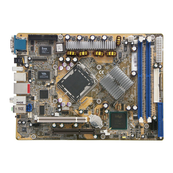
1.2 Item Checklist: Check all items with your FB77 mainboard to make sure nothing is missing. A complete package should include: - One Shuttle FB77 Mainboard USB3 FAN1 JP12 CN3 LAN1 JP11 PCI1 FAN3 ATX2 FAN2 DIMM1 DIMM2 ATX1 IDE2... -
Page 12: Features
2 FEATURES FB77 mainboard is dedicatedly designed for demanding PC users who desire high perfor- mance and maximum intelligent features in a compact package. 2.1 Specifications - CPU Support Intel Pentium 4 and Celeron D in the 775 pin package with 533/800 MHz FSB. -
Page 13: Pci Bus
- 8 USB Interface Onboard Ø USB 2.0/1.1 compliant. 4 UHCI HUB 1.1 Host controller and 1 EHCI USB2.0 Host controller support up to 8 USB ports. All 8 USB ports cna be assigned to USB 2.0 interface with BIOS option. - Onboard PWM ADP3180 with ADP3418 MOSFET drives (Four PHASE), supports over current/voltage protections, compliants with VRM10 specification. -
Page 14: System Bios
- Advanced Configuration and Power Interface Features four power-saving modes: S1 (Snoop), S3 (Suspend to RAM), S4 (Suspend to DISK), and S5 (Soft-Off). ACPI provides more efficient energy- saving features controlled by your operating system that supports OS Direct Power Management (OSPM) functionality. - System BIOS Provides licensed Award BIOS V6.0 PG on the 4Mb Flash ROM and sup- ports Green PC, Desktop Management Interface (DMI). -
Page 15: Hardware Installation
Cards and Cables, please unplug the onboard power connector. This section outlines how to install and configure your mainboard. Referring to the follow- ing mainboard layout helps you identify various jumpers, connectors, slots and ports. 3.1 Step-by-Step Installation (Accessories Of FB77) 10/100/1000 Mbps PS2 Mouse &... -
Page 16: Step 1 Cpu Installation
Step 1 CPU Installation: This motherboard supports Socket 775 Intel Pentium 4 and Celeron D pro- cessors (CPU). To install, follow the steps outlined below. Note the CPU orientation carefully when you insert it into the socket. Caution : This 775 pin socket is fragile and easily damaged. Always use extreme care when installing a CPU and limit the number of times that you remove or change the CPU. - Page 17 3. Orientate the CPU and socket, aligning the yellow triangle on the corner of the CPU with the triangle on the socket. Gently insert. Take care not to place any sideways force on the CPU when inserting, as the socket is fragile and easily damaged.
-
Page 18: Step 2 Set Jumper
Step 2 Set Jumper This mainboard is jumperless! The default jumper settings have been set for the common usage standard of this mainboard. Therefore, you do not need to reset the jumpers unless you require special adjustments as any of the following cases: 1. -
Page 19: Step 4 Install Internal Peripherals In System Case
Step 4 Install Internal Peripherals in System Case Before you place the mainboard into your system case, we recommend that you first assemble all the internal peripheral devices into the computer hous- ing, including, but not limited to, the hard disk drive (IDE/HDD), floppy disk drive (FDD), CD-ROM drive, and ATX power supply unit. -
Page 20: Step 5 Mount The Mainboard On The Computer Chassis
Step 5 Mount the Mainboard on the Computer Chassis 1. You may find there are a lot of mounting holes on your computer chassis and mainboard. To match the holes on both properly, the key point is to make the back-panel of the mainboard in a close fit with your system case, as shown below. -
Page 21: Connector (Jp16)
Step 6 Connect Front Panel Header You can find there are several different cables already existing in the system case and originatinting from the computer's front-panel devices (HDD LED, Power LED,or Reset Switch devices etc.) These cables serve to connect the front-panel switches and LEDs connectors to the mainboard's front-panel con- nectors group, as shown below. -
Page 22: Step 7 Connect Ide, Floppy Disk Drives And Serial Ata Connectors
Step 7 Connect IDE, Floppy Disk Drives and Serial ATA connectors 1. IDE cable connectors IDE2 IDE1 2. Floppy cable connector FDD1 3. Serial ATA connectors - 17 -... -
Page 23: Step 8 Connect Other Internal Peripherals
Step 8 Connect Other Internal Peripherals 1. Wireless KB/MS header (JP6) Wireless KB/MS 2. CD_IN (JP12) connector; LINE_IN (JP11) connector CD_IN LINE_In JP12 JP11 3. SPDIF Out header (J2) SPDIF Out - 18 -... - Page 24 4. Extended parallel port header (JP8) Ext. Print Port 5. IrDA connector (JP7) IR Connector 6. USB headers (USB3/USB4/USB5) USB3 Dual USB Header USB4 USB5 - 19 -...
-
Page 25: Step 9 Connect The Power Supplies
Step 9 Connect the Power Supplies 1. System power connectors (ATX1/ATX2) ATX2 ATX1 Step 10 Install Add-On Cards in Expansion Slots 1. Accelerated Grapics Port (AGP) Card 2. PCI Card - 20 -... -
Page 26: Step 11 Connect External Peripherals To Back-Panel
Step 11 Connect External Peripherals to Back-Panel You are now ready to connect the external peripherals to your system's back- panel. COM Ports 1/2 SPDIF-In Port 1394a Port PS/2 Mouse Port PS/2 Keyboard Port 6. 10/100/1000 Mbps LAN Port USB Ports 1/2 SPDIF Out RCA Port Line-In Port 10. -
Page 27: Step 12 System Boot Up For The First-Time
Step 12 System Boot Up For the First-Time To ensure your system completedly and correctly installed, please refer to the above installation steps once again before first booting up your system. 1. Insert a system-bootable floppy disk (DOS 6.2X, Windows 9X/NT, or others), which contains the FDISK and FORMAT utilities. -
Page 28: Step 13 Install Drivers & Software Components
2000/ME/NT/XP operating systems. Make sure your operating system is already installed before running the installation programs on CD-ROM. 1. Insert the FB77 bundled CD-ROM into your CD-ROM drive. The autorun program will display the main installation window on screen. 2. Choose "Install Mainboard FB77 Series Driver". -
Page 29: Jumper Settings
3.2 Jumper Settings Several hardware settings are made through the use of mini jumpers to con- nect jumper pins on the mainboard. Pin #1could be located at any corner of jumpers, and the corner with a white right angle stands for Pin #1. There are several types of Pin #1 as shown below: 3-pin and multi-pin (>3) jumpers shown as follows: Pin #1 to the left:... -
Page 30: Jumpers & Connectors Guide
Jumpers & Connectors Guide Refer to the mainboard layout on page 10 and this section to help you iden- tify jumpers, slots and connectors along with their assigned functions. B4~B5 B10~B12 B8~B9 B6~B7 C1~C4 CPU/Memory/Expansion Slots LGA 775 : CPU Socket for Intel Pentium 4 and Celeron D processors DIMM1/2 : Two DIMM slots for 128, 256 and 512 MB of 2.5V DDR SDRAM... -
Page 31: Jumpers
Jumpers : Clear CMOS setting Back-Panel Connectors COM 1/2 : COM port connectors SPDIF-In : SPDIF-In Port 1394a : IEEE1394a port connector : PS/2 Mouse port connector : PS/2 Keyboard port connector : 0/100/1000 Mbps LAN Port : USB 1/2 port connectors SPDIF Out RCA : SPDIF Out RCA Port Line-In : Line In port connector... -
Page 32: Clear Cmos Setting (Jp1)
JP11 : CD_IN connector : IrDA header : SPDIF Out header : Wireless KB/MS header : Extended parallel port header JP12 : LINE_IN connector USB3/4/5 : USB Headers Jumpers Clear CMOS Setting (JP1) JP1 is used to clear CMOS data. Clearing CMOS will result in permanently erasing previous system configuration settings and the original factory-set system settings. -
Page 33: Back-Panel Connectors
Back-Panel Connectors COM1/2 Port Connectors COM1/2 Ports This mainboard can accommodate one serial device on COM1/2. Attach a se- rial device cable to the DB9 serial ports at the back-panel of your computer. SPDIF-IN Connector SPDIF IN connector can accept digital audio data from Optic fiber. -
Page 34: Spdif Out Rca Port Connector
SPDIF Out RCA Port SPDIF Out RCA Port Connector SPDIF Out RCA connector can out- put digital audio data from SPDIF Out RCA. Line-In Port Connector Line-In is a stereo line-level input port that accepts a 1/8-inch TRS ste- reo plug. It can be used as a source for digital sound recording, a source to be mixed with the output, or both. -
Page 35: Front-Panel Connectors Hdd Led Connector (Hled)
Front-Panel Connectors HDD LED Connector (HLED) Attach a connector cable from the IDE device LED to the 2-pin (HLED) header. The HDD LED lights up whenever an IDE device is active. JP13 PWON HLED GLED / PWR LED Green LED/Power LED Connector (GLED/PWR LED) This header is dual color LED function. -
Page 36: Hardware Reset Connector (Rst)
Hardware Reset Connector (RST) Attach a cable to the 2-pin (RST) header. Pressing the reset switch causes the system to restart. JP13 PWON HLED GLED / PWR LED ATX Power On/Off Switch Connector (PWON) The Power On/Off Switch is a momentary type switch used for turning on or off the ATX power supply. -
Page 37: Front Panel Audio/Usb/1394 Connector (Jp16)
Front Panel Audio/USB/1394 Connector (JP16) Port JP16 can used to connect special device. Front Panel Audio/ USB/1394 Connector JP16 Pin Assignments: 1=USBVCC 3=USBVCC 2=USBVCC 4=USBVCC 6=USBVCC 5=USBVCC 7=USBVCC 9=USB5+ 8=USBVCC 10=USB5- 12=GND 11=GND 13=USB4+ 15=GND 14=USB4- 16=GND 18=TPA1- 17=TPA1+ 19=GND 21=TPB1+ 20=GND 22=TPB1-... -
Page 38: Internal Peripheral Connectors Enhanced Ide And Floppy Connectors (Ide1/Ide2 & Fdd1)
Internal Peripheral Connectors Enhanced IDE and Floppy Connectors (IDE1/IDE2 & FDD1) FB77 mainboard features two 40-pin dual-channel IDE device connectors (IDE1/IDE2), providing support for up to four IDE devices, such as CD-ROM and Hard Disk Drive (HDD). This mainboard also includes one 34-pin floppy disk controller (FDC) to accommodate the Floppy Disk Drive (FDD). -
Page 39: Other Connectors Atx Power Supply Connectors (Atx1/Atx2)
Other Connectors ATX Power Supply Connectors (ATX1/ATX2) This motherboard uses 20-pin ATX power header (ATX1), and comes with the other one header (ATX2). Please make sure you plug each in the right direction. It is essential to have these two power supply connectors plugged or your system won't boot up. -
Page 40: Fan Connectors (Fan1/2/3)
Fan Connectors (FAN1/2/3) The mainboard provides three onboard 12V cooling fan power connectors. FAN_SEN FAN1 +12V Ground FAN_CTRL +12V SENSE FAN2 Note: Both cable wiring and type of plug may vary, which depend on the fan maker. Keep in mind that the red wire should always be connected to the +12V header and the black wire to the ground (GND) header. -
Page 41: Ir Header (Jp7)
IR Header (JP7) If you have an Infrared device, this mainboard can implement IR transfer function. This mainboard supports IrDA, ASKIR, or SCR transfer mode. To enable this function, attach a 6-pin infrared device cable to the IR (JP7) header. Please note that every pin is properly allocated. If not, your IR device may be damaged. -
Page 42: Wireless Kb/Ms Header (Jp6)
Wireless KB/MS Header (JP6) Port JP6 can be used to connect wireless keyboard and mouse devices. 11 9 7 5 3 1 Wireless KB/MS 12 10 8 6 4 2 Pin Assignments: 7=MS_DT 1=VCC 8=MDAT 2=VCC 9=KB_CK 3=Ground 10=KCLK 4=Key 11=KB_DT 5=MS_CK 12=KDAT... -
Page 43: Line_In Connector (Jp12)
LINE_IN Connector (JP12) Port JP12 (Blue) can be used as a source for digital sound recording, a source to be mixed with the output, or both. JP12 LINE_In 1 2 3 4 Pin Assignments: JP12 1=Line-In (Left) 2=Ground 3=Ground 4=Line-In (Right) USB Headers (USB3/USB4/USB5) Headers USB3 &... -
Page 44: System Memory Configuration
3.3 System Memory Configuration The FB77 mainboard has two 184-pin DIMM slots that allow you to install from 64MB up to 2GB of system memory. Each 184-pin DIMM (Dual In-line Memory Module) slot can accommdate 64MB, 128MB, 256MB, 512MB, and 1GB of PC2700/PC3200 compliant 2.5V single or double side 64-bit wide data path DDR SDRAM modules. -
Page 45: Software Utility
F Install Mainboard FB77 Driver - Installing Intel Chipset, Realtek Audio, Broadcom Giga LAN, Broadcom BACS, Intel Raid, Intel USB 2.0 and DirectX9 Utility Drivers. F Manual - FB77 user's manual and ICH5R RAID User's Guide in PDF format. 4.2 Install Mainboard Software Select using your pointing device (e.g. -
Page 46: A Install Intel Chipset Driver
4.2.A Install Intel Chipset Driver Select using your pointing device (e.g. mouse) on the "Intel Chipset Driver" bar to install Intel chipset. Once you made your selection, a Setup window run the installation automatically. When the copying files is done, make sure you reboot the system to take the installation effect. -
Page 47: C Install Broadcom Giga Lan Driver
4.2.C Install Broadcom Giga LAN Driver Select using your pointing device (e.g. mouse) on the "Broadcom Giga LAN Driver" bar to install Broadcom Giga LAN driver. Once you made your selection, a Setup window run the installation automatically. When the copying files is done, make sure you reboot the system to take the installation effect. -
Page 48: E Install Intel Raid Driver
4.2.E Install Intel Raid Driver Select using your pointing device (e.g. mouse) on the "Intel Raid Driver" bar to install Raid driver. Once you made your selection, a Setup window run the installation automatically. When the copying files is done, make sure you reboot the system to take the installation effect. -
Page 49: G Install Directx9 Utility Driver
Select using your pointing device (e.g. mouse) on the "Manual" bar. Then Online Information windows will appear on your screen. Click on the "Install Acrobat Reader" bar if you need to install acrobat reader or click on the "FB77 Manual" bar to view the manual. - 44 -... -
Page 50: A View The Ich5R Manual
4.3A View the ICH5R Manual Select using your pointing device (e.g. mouse) on the "Manual" bar. Click on the "ICH5R Manual" bar to view the manual. - 45 -... -
Page 51: Bios Setup
5 BIOS SETUP FB77 BIOS ROM has a built-in Setup program that allows users to modify the basic system configuration. This information is stored in battery-backed RAM so that it retains the Setup information even if the system power is turned off. -
Page 52: The Main Menu
5.2 The Main Menu Once you enter the Award BIOS(tm) CMOS Setup Utility, the Main Menu will appear on the screen. The Main Menu allows you to select from several setup functions and two exit choices. Use the arrow keys to select among the items and press <Enter>... - Page 53 PnP/PCI Configurations This option configures how PnP (Plug and Play ) and PCI expansion cards operate in your system. PC Health Status This entry shows the current system temperature, voltage, and fan speed. Frequency/Voltage Control Use this menu to specify your settings for the frequency/voltage control. Load Fail-Safe Defaults Use this menu to install fail-safe defaults for all appropriate items in the setup utility.
-
Page 54: Sandard Cmos Features
Standard CMOS Features Use the arrow keys to highlight the item and then use the <PgUp> or <PgDn> keys to select the value you want in each item. Date (mm : dd : yy) Set the system date. Note that if you are running a Windows OS, this items are automatically updated whenever you make changes to the Windows Date. - Page 55 Base Memory/Extended Memory/Total Memory These items are automatically detected by the system at start up time. These are display-only fields. You can't make change to these fields. ****************************************************** IDE Adapters The IDE adapters control the hard disk drive. Use a separate sub-menu to configure each hard disk drive.
-
Page 56: Advanced Bios Features
Advanced BIOS Features This section allows you to configure your system for basic operation. You have the opportunity to select the system's default speed, boot-up sequence, keyboard operation, shadowing, and security. CPU Feature Options are in its sub-menu. Press <Enter> to enter the sub-menu of detailed options. Delay Prior to Thermal This item is select Delay Prior to Thermal. - Page 57 TM2 Bus VID Represents the voltageof the throttled performance statethat will be initi- ated when the on diesensor gose from not hot to hot. Ø The Choice: 0.8375V ~1.6000V. Note: CPU support TM2, item appear. Limit CPUID MaxVal Set Limit CPUID MaxVal to 3,Should Be "Disabled" for WinXp. Ø...
- Page 58 CPU L1&L2&L3 Cache All processors that can be installed in this mainboard use internal level1(L1) , external 2(L2) and (L3) cache memory to imporve performance. Leave this item at the default value for better performance. Ø The choice: Enabled or Disabled. Note: CPU support, L3 item appear.
-
Page 59: Gate A20 Option
Ø The choice: Off or On. Gate A20 Option This entry allows you to select how the Gate A20 is handled. The gate A20 is a device used for above 1MByte of address memory. Initially, the gate A20 was handled via a pin on the keyboard. Today, while a key- board still provides this support, it is more common and much faster in setting to fast for the system chipset to provide support for gate A20. - Page 60 APIC Mode Via the routing, I/O APIC support a total of 24 interrupts. We recommend to choose [Enabled] for Windows XP and Windows 2000. Ø The choice: Enabled or Disabled. MPS Version Control For OS Selects the operating system multiprocessor support version. Ø...
-
Page 61: Advanced Chipset Features
Advanced Chipset Features This section allows you to configure the system based on the specific features of the installed chipset. This chipset manages bus speeds and access to system memory resources, such as DRAM and the external cache. It also coordinates communications between the conventional ISA bus and the PCI bus. - Page 62 DRAM RAS # to CAS # Delay This field lets you insert a timing delay between the CAS and RAS strobe signals, and you can use it when DRAM is written to, read from, or re- freshed. Faster performance is gained in high speed, more stable perfor mance, in low speed.
- Page 63 Init Display First This item is used to determine initial device when system power on. Ø The choice: PCI Slot or AGP. DRAM Data Integrity Mode This item allows you to set DRAM Data Integrity Mode. Ø The Choice: Non-ECC or ECC. Fast Chip Select This item allows you to set Fast Chip.
-
Page 64: Integrated Peripherals
Integrated Peripherals On-Chip IDE Device Option are in its sub-menu. Press<Enter>to enter the sub-menu of detailed options. IDE HDD Block Mode If your IDE hard disk drive supports block mode (most new drives do), select Enabled to automatic detect the optimal number of block read and writes per sector that the drive can support and improves the speed of access to IDE devices. - Page 65 IDE Primary Master/Slave UDMA Each IDE channel supports a master device and a slave device. This mainboard supports UltraDMA technology, which provides faster access to IDE devices. If you install a device that supports UltraDMA, change the appropriate item on this list to Auto. You may have to install the UltraDMA driver supplied with this mainboard in order to use an UltraDMA device.
- Page 66 Combined Mode:PATA and SATA are combined. Max. of 4 ATA drives in each channel. (DOS, Win98/ME) should set SATA and PATA to Compatible Mode. (Channel 0) Serial ATA 1 (Channel 0) Serial ATA 1 Slave Master Primary Primary Master Slave (Channel 0) Serial ATA 2 (Channel 0)
- Page 67 Enhanced Mode:Enable both SATA and PATA. Max. of 6 ATA drives are supported. New OS that support switch to Enhanced mode (Win2K, WinXP, Windows.NET Server) can set SATA and PATA to Enhanced Mode. Serial ATA 1 (Channel 2) Primary Master (Channel 3) or Secondary Serial ATA 2...
-
Page 68: Onboard Device
Onboard Device Option are in its sub-menu. Press<Enter>to enter the sub-menu of detailed options. USB Controller Select Enabled if your system contains a Universal Serial Bus (USB) port on this mainboard. Ø The choice: Enabled or Disabled. USB 2.0 Controller Select Enabled if your system contains a Universal Serial Bus (USB) 2.0 controller and you have USB peripherals. - Page 69 or Auto. UART Mode Select This item allows you to select an operating mode for the IrDA infrared. Ø The choice: IrDA, ASKIR, or SCR. UR2 Duplex Mode This item allows you to select the IR half or full duplex function. Ø...
-
Page 70: Power Management Setup
Power Management Setup The Power Management Setup allows you to configure your system to most effectively saving energy while operating in a manner consistent with your own style of computer use. ACPI Function This item allows you to enable/disable the Advanced Configuration and Power Management (ACPI). - Page 71 Video Off Method This determines the manner in which the monitor is blanked. V/H SYNC+Blank This selection will cause the system to turn off the vertical and horizontal synchronization ports and write blanks to the video buffer. Blank Screen This option only writes blanks to the video buffer.
-
Page 72: Reload Global Timer Events
Sec. then you have to hold the power button down for 4 seconds to cause a software power down. Ø The choice: Instant-Off or Delay 4 Sec. Wake-Up by PCI card This item Enabled/Disabled PCI Power Management Event to wake up system. - Page 73 Ø The choice: Disabled or Enabled. FDD, COM, LPT Port When this item is enabled, the system will restart the power-saving timeout counters when any activity is detected on the floppy disk drive, serial ports, or the parallel port. Ø The choice: Disabled or Enabled. PCI PIRQ [A-D] # When this item is disabled, any PCI device set as the Master will not power on the system.
-
Page 74: Pnp/Pci Configurations
PnP/PCI Configurations This section describes the configuration of PCI bus system. PCI or Per- sonal Computer Interconnection is a system which allows I/O devices to operate at the speed CPU itself keeps when CPU communicating with its own special components. This section covers some very technical items, and it is strongly recom- mended that only experienced users should make any changes to the default settings. - Page 75 IRQ Resources When resources are controlled manually, assign each system interrupt a type, depending on the type of device using the interrupt. IRQ3/4/5/7/10/11/12/14/15 assigned This item allows you to determine the IRQ assigned to the ISA bus and is not available to any PCI slot. Legacy ISA for devices is compliant with the original PC AT bus specification;...
-
Page 76: Pc Health Status
PC Health Status CPU Fan Speed Control Set the CPU Fan Speed. Ø The choice: Smart Fan, Ultra-Low, Low , Mid , or Full. Note : Before manually modifying the CPU fan setting, please make sure fan connectors are plug into the correct fan connector designations on the mainboard. - Page 77 CPU Temp Tag The item only for 'smart fan' and you can choose 'smart fan' on 'CPU Fan Speed Control'. This feature ranges from 25 C to 75 C, in an increment of 1 C. When CPU current tempera- ture over CPU Temp Tag, CPU fan will speed up.
-
Page 78: Frequency/Voltage Control
Frequency/Voltage Control CPU Clock Ratio This item allows the user to adjust CPU Clock Ratio. If CPU is unlocked, item appear. Ø The Choice: 8X~50X. Auto Detect PCI Clk This item allows you to enable/disable auto disable empty PCI Slot Clock. - Page 79 Async AGP/PCI/S-ATA CLK If You install S-ATA device, please do not select "Sync by CPU clock". That will let S-ATA device fail. We strongly recommend You to select "fixed 66/33/100 MHz". Ø The choice: Sync by CPU clock, fixed 66/33/100 MHz, fixed 73/36/ 100 MHz or fixed 80/40/100 MHz.
-
Page 80: Load Fail-Safe Defaults
Load Fail-Safe Defaults When you press <Enter> on this item, you will get a confirmation dialog box with a message similar to: Load Fail-Safe Defaults (Y/N) ? N Pressing 'Y' loads the BIOS default values for the most stable, minimal performance system operations. Load Optimized Defaults When you press <Enter>... -
Page 81: Set Supervisor/User Password
Set Password This item is to set supervisor password. Please follow below steps. New Password Setting : 1. While pressing <Enter> key to start setting password function, a dialog box appears to ask you “Enter password: “. 2. Key in a new password now. However, the password can not be over eight characters or numbers. -
Page 82: Save & Exit Setup
Save & Exit Setup Pressing <Enter> on this item asks for confirmation: Save to CMOS and EXIT (Y/N)? Y Pressing "Y" stores the selections made in the menus of CMOS - a special section of memory that stays on after you turn your system off. The next time you boot your computer, the BIOS configures your system according to the Setup selections stored in CMOS.
Need help?
Do you have a question about the FB77 and is the answer not in the manual?
Questions and answers