Table of Contents
Advertisement
Quick Links
Advertisement
Table of Contents

Related Manuals for Shuttle FB52


Summary of Contents for Shuttle FB52
- Page 1 FB52 Pentium 4/Celeron , 478-pin Processor Based MAIN BOARD...
- Page 2 The information contained in this manual is provided for general use by the customers. Trademarks Shuttle is a registered trademark of Shuttle Inc. Intel, Pentium are registered trademarks of Intel Corporation. PS/2 is a registered trademark of IBM Corporation.
-
Page 3: Table Of Contents
2.1 SPECIFICATIONS ..................8 3 HARDWARE INSTALLATION ............11 3.1 STEP BY STEP INSTALLATION ..............11 Accessories of FB52 ................11 STEP 1 CPU Installation ................ 12 STEP 2 Set Jumpers ................14 STEP 3 Install DDR SDRAM System Memory ........14 STEP 4 Install Internal Peripherals in System Case ........ - Page 4 3.2 JUMPER SETTINGS ................. 24 JUMPERS & CONNECTORS GUIDE ............ 25 Jumpers Clear CMOS Setting (JP2) ..............28 Back-Panel Connectors COM1 Port Connectors ................. 29 VGA Port Connector ................29 SPDIF_Out Port ..................29 Giga LAN Connector ................29 10/100 base-T LAN Port Connector ............29 USB0/1 Port Connectors ...............
- Page 5 Wireless Keyboard and Mouse Headers (JP5)........36 Parallel Port Header (JP9) ..............37 IR Header (JP8) ..................37 Audio Aux_IN Connector(CN11)(White) ..........38 SPDIF-IN Headers (JP10) ..............38 3.3 SYSTEM MEMORY CONFIGURATION ............. 39 INSTALL MEMORY ................39 UPGRADE MEMORY ................39 4 SOFTWARE UTILITY ..............
- Page 6 PC HEALTH STATUS ................71 FREQUENCY/RATIO CONTROL ............... 73 LOAD FAIL-SAFE DEFAULTS ..............74 LOAD OPTIMIZED DEFAULTS ..............74 SET PASSWORD ..................75 SAVE & EXIT SETUP ................76 EXIT WITHOUT SAVING ................76 - 4 -...
-
Page 7: What's In The Manual
WHAT'S IN THE MANUAL Quick Reference Hardware Installation >> Step-by-Step ..........Page 11 Jumper Settings >> A Closer Look ............Page 24 Drivers/Software Utilities >> How to Install .......... Page 40 BIOS Setup >> How to Configure ............Page 49 About This Manual For First-Time DIY System Builder ............ -
Page 8: Introduction
Experienced DIY User Congratulate on your purchase of the Shuttle FB52 mainboard. You will find that installing your new Shuttle FB52 mainboard is just easy. Bundled with an array of onboard functions, the highly-integrated FB52 mainboard provides you with a total solution to build the most stable and reliable system. Refer to sec- tions 3.2 Jumper Settings and Chapter 4 Drivers/Software Utilities to... -
Page 9: Item Checklist
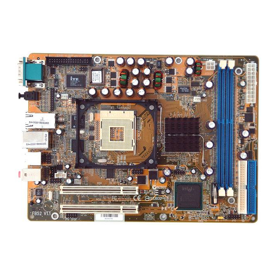
1.2 Item Checklist Check all items with your FB52 mainboard to make sure nothing is missing. The complete package should include: - One piece of Shuttle FB52 Mainboard ALC650 25193Q1 225E JP11 CD-IN CN11 PCI2 PCI1 FAN1 SPDIF AUX-IN FAN3... -
Page 10: Features
2 FEATURES FB52 mainboard is carefully designed for the demanding PC user who wants high perfor- mance and maximum intelligent features in a compact package. 2.1 Specifications - CPU Support Intel Pentium 4/Celeron, 478-pin processors with 400/533 MHz FSB. - Chipset Features Intel 845GV GMCH N.B. - Page 11 Provides licensed Award BIOS V6.0 PG on 4Mb Flash core and supports Green PC, Desktop Management Interface (DMI). - Form Factor System board conforms to Shuttle from factor ATX specification. Board dimension: 254mm x 185mm. - Advanced Features Ø Low EMI - Built in spread spectrum and automatic clock shut-off of unused PCI/SDRAMS slots to reduce EMI.
- Page 12 Ø Dual Function Power Button - The system can be in one of two states, one is Suspend mode and the other is Soft-Off mode. Pushing the power button for less than 4 seconds places the system into Suspend mode. When the power button is pressed for longer than 4 seconds, the system enters Soft-Off mode.
-
Page 13: Hardware Installation
Then follow these steps designed to guide you through a quick and correct installation of your system. 3.1 Step-by-Step Installation Accessories Of FB52 Gigabit LAN Connector 10/100M LAN & USB 2.0 Connectors Wireless KB and MS... -
Page 14: Step 1 Cpu Installation
Step 1 CPU Installation: This mainboard supports Intel Pentium 4/Celeron, Socket 478 series CPU. Please follow the step as below to finish CPU installation. Be careful of CPU orientation when you plug it into CPU socket. 1. Pull up the CPU socket lever and up to 90-degree angle. CPU socket lever up to 90 degree 2. - Page 15 3. Press down the CPU socket lever and finish CPU installation. Note: If you do not match the CPU socket Pin 1 and CPU cut edge well, it may damage the CPU. 4. The Intel Pentium 4/Celeron processor requires a set of heatsink/fan to en sure proper cooling of the processor.
-
Page 16: Step 2 Set Jumpers
Step 2. Set Jumpers This mainboard is jumperless! The default jumper settings have been set for the common usage standard of this mainboard. Therefore, you do not need to reset the jumpers unless you require special adjustments as any of the following cases: 1. -
Page 17: Step 4 Install Internal Peripherals In System Case
Step 4 Install Internal Peripherals in System Case Before you install and connect the mainboard into your system case, we recommend that you first assemble all the internal peripheral devices into the computer housing, including but not limited to the hard disk drive (IDE/ HDD), floppy disk drive (FDD), CD-ROM drive, and ATX power supply unit. -
Page 18: Step 5 Mount The Mainboard On The Computer Chassis
Step 5 Mount the Mainboard on the Computer Chassis 1. You may find that there are a lot of different mounting hole positions both on your computer chassis and on the mainboard. To choose correct mounting holes, the key point is to keep the back-panel of the mainboard in a close fit with your system case, as shown below. -
Page 19: Step 6 Connect Front Panel Switches/Leds/Speaker/Usb
Step 6 Connect Front Panel Switches/LEDs/Speaker/USB You can find there are several different cables already existing in the system case and originatinting from the computer's front-panel devices (HDD LED, Power LED, Reset Switch, or USB devices etc.) These cables serve to connect the front-panel switches, LEDs, and USB connectors to the mainboard's front-panel connectors group (JP6, JP7, JP12), as shown below. -
Page 20: Step 7 Connect Ide And Floppy Disk Drives
6. SPDIF_In header (JP10) SPDIF_In JP10 7. CD-IN (CN5) and AUX_IN (CN11) Headers AUX-IN CD-IN CN11 Step 7 Connect IDE and Floppy Disk Drives 1. IDE cable connector IDE2 IDE1 - 18 -... -
Page 21: Step 8 Connect Other Internal Peripherals
2. Floppy cable connector Step 8 Connect Other Internal Peripherals 1. IR Headers (JP8) 2. Wireless keyboard and mouse headers (JP5) Wireless KB/MS - 19 -... -
Page 22: Step 9 Connect The Power Supply
Step 9 Connect the Power Supply 1. System power connector(CN7/CN6) ATX12V ATXPWR Step 10 Install Add-on Cards in Expansion Slots 1. PCI Card - 20 -... -
Page 23: Step 11 Connect External Peripherals To Back-Panel
Step 11 Connect External Peripherals to Back-Panel You are now ready to put the computer case back together and get on to the external peripherals connections to your system's back-panel. COM1 Port VGA Port SPDIF Out Port GigaLAN Port 10/100M LAN Port USB0/1 Ports PS/2 Mouse PS/2 Keyboard... -
Page 24: Step 12 First Time System Boot Up
Step 12 First Time System Boot Up To assure the completeness and correctness of your system installation, you may check the above installation steps once again before you boot up your system for the first time. 1. Insert a bootable system floppy disk (DOS 6.2x, Windows 95/98/NT, or others) which contains FDISK and FORMAT utilities into the FDD. -
Page 25: Step 13 Install Drivers & Software Components
2000/ME/XP/NT operating systems only. Make sure your operating system is already installed before running the drivers installation CD-ROM programs. 1. Insert the FB52 bundled CD-ROM into your CD-ROM drive. The autorun program will display the drivers main installation window on screen. -
Page 26: Jumper Settings
3.2 Jumper Settings Several hardware settings are made through the use of mini jumpers to con- nect jumper pins on the mainboard. Pin #1 could be located at any corner of each jumper, you just find the location with a white right angle which stands for pin 1#. -
Page 27: Jumpers & Connectors Guide
Jumpers & Connectors Guide Use the mainboard layout on page 11 to locate CPU socket, memory banks, expansion slots, jumpers and connectors on the mainboard during the instal- lation. The following list will help you to identify jumpers, slots, and connec- tors along with their assigned functions: B5~B6 B8~B10... -
Page 28: Jumpers
Jumpers : Clear CMOS setting Back Panel Connectors COM1 : Serial port 1 (DB9 male) : VGA port (DB15 female) SPDIF_Out : SPDIF Out Port LAN2 : GigaLAN Port LAN1 : 10/100 base-T LAN Port USB1 : 2 USB 2.0 (0/1) (Universal Serial Bus) ports : PS/2 mouse port : PS/2 keyboard port BASS/CENTER... - Page 29 FAN3 : CPU fan connector : Audio CD_IN connector : Wireless Keyboard and Mouse connector : Parallel port header : IR Header CN11 : AUX_IN connector JP10 : SPDIF_In header - 27 -...
-
Page 30: Clear Cmos Setting (Jp2)
Jumpers Clear CMOS Setting (JP2) JP2 is used to clear CMOS data. Clearing CMOS will result in the perma- nently erasing previous system configuration settings and the restoring origi- nal (factory-set) system settings. Pin 1-2 (Default) Clear CMOS Pin 2-3 (Clear CMOS) Step 1. -
Page 31: Com1 Port Connectors
Back-Panel Connectors COM1 Port Connector COM1 Port This mainboard can accommodate two serial device on COM1. Attach a serial device cable to the DB9 serial port COM1 at the back-panel of your computer. VGA Connector One 15-pin VGA connector is located at the rear panel of the mainboard. -
Page 32: Ps/2 Keyboard & Ps/2 Mouse Connectors
PS/2 Keyboard & PS/2 Mouse Connectors Two 6-pin female PS/2 keyboard & PS/2 Mouse Mouse connectors are located at the rear panel of the mainboard. Depending on the computer housing you use (desktop or tower), the PS/2 Mouse connector is situated at the top of the PS/2 Keyboard connector when the mainboard is laid into a desktop, as PS/2 keyboard... -
Page 33: Front-Panel Headers Atx Power On/Off Switch Header (Pwon)
Front-Panel Connectors ATX Power On/Off Switch Connector (PWON) The Power On/Off Switch is a momentary type switch used for turning on or off the system ATX power supply. Attach the connector cable from the Power Switch to the 2-pin (PWON) header on the mainboard. Front Panel 1 JP12 Note : Please notice all the LED connectors are directional. -
Page 34: Green Led / Power Led Header (Gled/Pled)
Green LED / Power LED Connector (GLED/PLED) This header is dual color LED function. Dual color LED function is defined by either Power LED or Green LED, the header can be in these states. The Green LED indicates that the system is currently in one of the power sav- ing mode (Doze/Standby/Suspend). -
Page 35: Extended Usb Headers (Jp6/Jp7)
Extended USB Header (JP6/JP7) The headers are used to connect the cable attached to USB connectors which are mounted on front panel or back panel. But the USB cable is optional at the time of purchase. USB port 3 USB port 2 Pins Assignment: 1=+5V 2=+5V... -
Page 36: Internal Peripherals Connectors
Internal Peripherals Connectors Enhanced IDE and Floppy Connectors The mainboard features two 40-pin dual-channel IDE device connectors (IDE1/IDE2) providing support for up to four IDE devices, such as CD-ROM and Hard Disk Drives (H.D.D.). This mainboard also includes one 34-pin floppy disk controller (FDC) to accommodate the Floppy Disk Drive (FDD). -
Page 37: Other Connectors
Other Connectors ATX Power Supply Connectors (CN6 and CN7) This motherboard uses 20-pin (CN7) Pentium 4 standard ATX power header, and CN6 with 2X2-pin +12V PC ATX power supply headers. Please make sure you plug in the right direction. P4 ATX Power supply headers ATX12V ATXPWR Note 1:... -
Page 38: Cpu And System Fan Connector (Fan1/2/3)
CPU and System Fan Connectors - FAN1/2/3 The mainboard provides three onboard 12V cooling fan power connectors to support System (FAN1), Chipset (FAN2), or CPU (FAN3) cooling fans. FAN1 +12V SENSE FAN3 Note: Both cable wiring and type of plug may vary , which depends on the fan maker. -
Page 39: Parallel Port Header (Jp9)
Parallel Port Header (JP9) One DB25 male parallel port header is located at the rear panel of the maiboard. The header is used to connect the cable attached to parallel connector. But the parallel cable and connector os optional at the time of purchase. Paralle Port IR Header (JP8) If you have an infrared device, this mainboard can implement IR tranfer func-... -
Page 40: Audio Aux_In Connector(Cn11)(White)
Audio AUX_IN Connector (CN11) Port CN11 can be used to connect a stereo audio input from CD-ROM, TV- tuner or MPEG card. AUX-IN CN11 SPDIF_In Headers (JP10) Port JP10 can be used to connect special device. SPDIF_In JP10 Pin Assignments: 1=+12V 2=VCC 3=N/A... -
Page 41: System Memory Configuration
3.3 System Memory Configuration The FB52 mainboard has two 184-pin DIMM slots that allow you to install from 64MB up to 2GB of system memory. Each 184-pin DIMM (Dual In-line Memory Module) Slot can accommodate 64MB, 128MB, 256MB, 512MB, and 1GB of PC1600 or PC2100 compliant 2.5V single (1 Bank) or double (2 Bank) side 64-bit wide data path DDR... -
Page 42: Software Utility
4 SOFTWARE UTILITY 4.1 Mainboard CD Overview Note: The CD contents attached in FB52 mainboard are subject to change without notice. To start your mainboard CD disc, just insert it into your CD-ROM drive and the CD AutoRun screen should appear. If the AutoRun screen does not appear, double click or run D:\Autorun.exe (assuming that your CD-ROM... -
Page 43: Install Mainboard Software
Insert the attached CD into your CD-ROM drive and the CD AutoRun screen should appear. If the AutoRun screen does not appear, double click on Autorun icon in My Computer to bring up Shuttle Mainboard Software Setup screen. Select using your pointing device (e.g. mouse) on the "Install Mainboard Software"... -
Page 44: A Install Intel Chipset Driver
Insert the attached CD into your CD-ROM drive and the CD AutoRun screen should appear. If the AutoRun screen does not appear, double click on Autorun icon in My Computer to bring up Shuttle Mainboard Software Setup screen. Select using your pointing device (e.g. mouse) on the "Install Intel Chipset Driver"... -
Page 45: B Install Ide Driver
Insert the attached CD into your CD-ROM drive and the CD AutoRun screen should appear. If the AutoRun screen does not appear, double click on Autorun icon in My Computer to bring up Shuttle Mainboard Software Setup screen. Select using your pointing device (e.g. mouse) on the "Install IDE Driver”... -
Page 46: C Install Vga Driver
Insert the attached CD into your CD-ROM drive and the CD AutoRun screen should appear. If the AutoRun screen does not appear, double click on Autorun icon in My Computer to bring up Shuttle Mainboard Software Setup screen. Select using your pointing device (e.g. mouse) on the"Install VGA Device Driver"... -
Page 47: D Install Audio Driver
Insert the attached CD into your CD-ROM drive and the CD AutoRun screen should appear. If the AutoRun screen does not appear, double click on Autorun icon in My Computer to bring up Shuttle Mainboard Software Setup screen. Select using your pointing device (e.g. mouse) on the "Install Audio Driver"... -
Page 48: E Install Lan Driver
Insert the attached CD into your CD-ROM drive and the CD AutoRun screen should appear. If the AutoRun screen does not appear, double click on Autorun icon in My Computer to bring up Shuttle Mainboard Software Setup screen. Select using your pointing device (e.g. mouse) on the "Install LAN Driver”... -
Page 49: F Install Usb2.0 Driver
Insert the attached CD into your CD-ROM drive and the CD AutoRun screen should appear. If the AutoRun screen does not appear, double click on Autorun icon in My Computer to bring up Shuttle Mainboard Software Setup screen. Select using your pointing device (e.g. mouse) on the "Install USB2.0 Driver"... -
Page 50: View The User's Manual
Insert the attached CD into your CD-ROM drive and the CD AutoRun screen should appear. If the AutoRun screen does not appear, double click on AutoRun icon in My Computer to bring up Shuttle Mainboard Software Setup screen. Select using your pointing device (e.g. mouse) on the " Manual " bar. -
Page 51: Bios Setup
5 BIOS SETUP FB52 BIOS ROM has a built-in Setup program that allows users to modify the basic system configuration. This information is stored in battery-backed RAM so that it retains the Setup information even if the system power is turned off. -
Page 52: The Main Menu
5.2 The Main Menu Once you enter the AwardBIOS(tm) CMOS Setup Utility, the Main Menu will appear on the screen. The Main Menu allows you to select from several setup functions and two exit choices. Use the arrow keys to select among the items and press <Enter> to accept and enter the sub-menu. - Page 53 PC Health Status This entry shows the current system temperature, Voltage, and FAN speed. Frequency/Ratio Control Use this menu to specify your settings for frequency/Ratio control. Load Fail-Safe Defaults Use this menu to load the BIOS default values for the minimal/stable performance of your system to operate.
-
Page 54: Standard Cmos Features
Standard CMOS Features The items in Standard CMOS Setup Menu are divided into several categories. Each category includes no, one or more than one setup items. Use the arrow keys to highlight the item and then use the <PgUp> or <PgDn> keys to select the value you want in each item. Date <Month>... - Page 55 IDE Secondary Slave Options are in its sub-menu. Press <Enter> to enter the sub-menu of detailed options. Drive A/Drive B Select the type of floppy disk drive installed in your system. Ø The choice: None, 360K, 5.25 in, 1.2M, 5.25 in, 720K, 3.5 in, 1.44M, 3.5 in, or 2.88M, 3.5 in.
- Page 56 IDE Primary Master Selecting 'manual' lets you set the remaining fields on this screen and select the type of fixed disk. "User Type" will let you select the number of cylinders, heads, etc., Note: PRECOMP=65535 means NONE ! Ø The choice: None, Auto, or Manual. Access Mode Choose the access mode for this hard disk.
-
Page 57: Advanced Bios Features
Advanced BIOS Features This section allows you to configure your system for basic operation. You have the opportunity to select the system's default speed, boot-up sequence, keyboard operation, shadowing, and security. BIOS Write Protect This item lets you to enable or disable the BIOS Write Protect. Ø... - Page 58 CPU Hyper-Threading If your CPU supports the hyper-threading function, please leave this item enabled. Ø The choice: Enabled, or Disabled. Quick Power On Self Test This item speeds up Power-On Self Test (POST) after you power on the computer. If it is set to enabled, BIOS will shorten or skip some check items during POST.
- Page 59 Typematic Rate Setting Keystrokes repeat at a rate determined by the keyboard controller. When this controller enabled, the typematic rate and typematic delay can be selected. Ø The choice: Enabled or Disabled. Typematic Rate (Chars/Sec) This item sets how many times the keystroke will be repented in a second when you hold the key down.
- Page 60 Report No FDD For Win 95 Whether report no FDD runs for Win 95 or not. Ø The choice: Yes or No. Small Logo(EPA) Show This item allows you to enable/disable the EPA Logo. Ø The choice: Enabled or Disabled. - 58 -...
-
Page 61: Advanced Chipset Features
Advanced Chipset Features This section allows you to configure the system based on the specific features of the installed chipset. This chipset manages bus speeds and access to system memory resources, such as DRAM and the external cache. It also coordinates communications between the conventional ISA bus and the PCI bus. - Page 62 DRAM RAS # to CAS # Delay This field lets you insert a timing delay between the CAS and RAS strobe signals, and you can use it when DRAM is written to, read from, or re- freshed. Faster performance is gained in high speed, more stable perfor- mance, in low speed.
- Page 63 Delay Transaction The chipset has an embedded 32-bit posted write buffer to support de- layed transactions cycles. Enabled this item to support compliance with PCI specification version 2.1. Ø The Choice: Enabled or Disabled. Delay Prior to Thermal Enable this item to set the delay time before the CPU enters auto thermal mode.
-
Page 64: Integrated Peripherals
Integrated Peripherals On-Chip Primary /Secondary PCI IDE Use these items to enable or disable the PCI IDE channels that are integrated on the mainboard. Ø The choice: Enabled or Disabled. IDE Primary Master/Primary Slave/Secondary Master/Secondary Slave PIO Each IDE channel supports a master device and a slave device. These four items let you assign which kind of PIO ( Programmed Input / Out- put ) is used by IDE devices. - Page 65 USB Controller Select Enabled if your system contains a Universal Serial Bus (USB) port on this mainboard. Ø The choice: Enabled or Disabled. USB 2.0 Controller Select Enabled if your system contains a Universal Serial Bus (USB) 2.0 controller and you have USB peripherals. Ø...
- Page 66 POWER ON Function Enable you to set power on paramenters. The default setting enables you to use a hot key to turn on the system. Ø The choice: Password, Hot KEY, Mouse Move, Mouse Click, Any KEY, Button Only, Keyboard 98. KB Power On Password You can select this item and press "...
- Page 67 UR2 Duplex Mode This item is available when UART 2 mode is set to either ASKIR or IrDA. This item enables you to determin the infrared function of the onboard infrared chip. The options are Full and Half ( default ). Full-duplex means that you can transmit and send information simulta- neously.
-
Page 68: Power Management Setup
Power Management Setup The Power Management Setup allows you to configure your system to most effectively saving energy while operating in a manner consistent with your own style of computer use. ACPI Function This item allows you to enable/disable the Advanced Configuration and Power Management (ACPI). - Page 69 Blank Screen This option only writes blanks to the video buffer. DPMS Initial display power management signaling. Ø The choice: V/H SYNC+Blank, Blank Screen, or DPMS Supported. Video Off In Suspend This item determines the manner in which the monitor is blanked. Ø...
- Page 70 Power On by Ring This item determine the system will resume by activating of modem ring. Ø The choice: Enabled or Disabled. USB Wake-up from S3 If you are using a USB keyboard, and the ACPI suspend type is set to S3, you can enable this item to allow a keystroke to wake up the system from power saving mode.
-
Page 71: Pnp/Pci Configurations
PnP/PCI Configurations This section describes the configuration of PCI bus system. PCI or Personal Computer Interconnection is a system which allows I/O devices to operate at the speed CPU itself keeps when CPU communicating with its own special components. This section covers some very technical items, and it is strongly recommended that only experienced users should make any changes to the default settings. - Page 72 IRQ Resources When resources are controlled manually, assign each system interrupt a type, depending on the type of device using the interrupt. IRQ3/4/5/7/9/10/11/12/14/15 assigned This item allows you to determine the IRQ assigned to the ISA bus and is not available to any PCI slot. Legacy ISA for devices is compliant with the original PC AT bus specification;...
-
Page 73: Pc Health Status
PC Health Status CPU Fan AutoGuardian This SMART Bios enabled 3 phase Variable Fan Speed and CPU tem- perature Control feature. Ø The choice: Enabled or Disabled. This feature is controlled via Bios, in which the CPU fan rotational speed sensing /control is governed by CPU temperature setting preselected in Bios. - Page 74 Take our default Setting for example, 1st and 2nd phase Variable Fan Speed and CPU temperature Control is as defined by "Fan Speed Up When CPU Temp". If actual CPU temp (reported by BIOS) stays below C then CPU fan speed will run at a quiet mode (1st phase) of approximately 2000 RPM.
-
Page 75: Frequency/Ratio Control
Frequency/Ratio Control CPU Clock Ratio This item allows you to adjust CPU Ratio. Min: 8 Max: 50 Ø Key in a DEC number: (Between Min and Max.) Auto Detect PCI Clk This item allows you to enable/disable auto detection DIMM/PCI Clock. Ø... -
Page 76: Load Fail-Safe Defaults
Load Fail-Safe Defaults When you press <Enter> on this item, you will get a confirmation dialog box with a message similar to: Load Fail-Safe Defaults (Y/N) ? N Pressing 'Y' loads the BIOS default values for the most stable, minimal performance system operations. Load Optimized Defaults When you press <Enter>... -
Page 77: Set Password
Set Password This item is to set supervisor password. Please follow below steps. New Password Setting : 1. While pressing <Enter> key to start setting password function, a dialog box appears to ask you “Enter password: “. 2. Key in a new password now. However, the password can not be over eight characters or numbers. -
Page 78: Save & Exit Setup
Save & Exit Setup Pressing <Enter> on this item asks for confirmation: Save to CMOS and EXIT (Y/N)? Y Pressing "Y" stores the selections made in the menus of CMOS - a special section of memory that stays on after you turn your system off. The next time you boot your computer, the BIOS configures your sys- tem according to the Setup selections stored in CMOS.
Need help?
Do you have a question about the FB52 and is the answer not in the manual?
Questions and answers