iSystem iC5000 Hardware Reference Manual
On-chip analyzer
Hide thumbs
Also See for iC5000:
- Hardware reference manual (69 pages) ,
- User manual (54 pages) ,
- User manual (20 pages)
Advertisement
Quick Links
_
V3.2
Hardware Reference
iC5000 On-Chip Analyzer
Thank you for purchasing this product from iSYSTEM. This product has been carefully crafted to satisfy your
needs. Should any questions arise, do not hesitate to contact your local distributor or iSYSTEM directly. Our
technical support personnel will be happy to answer all your technical support questions.
All information, including contact information, is available on our web site www.isystem.com. Feel free also to
explore our alternative products.
iSystem constantly yields for development and therefore certain pictures in this documentation may vary slightly
from the actual product you received. The differences should be minor, but should you find more serious
inconsistencies of the product with the documentation, please contact your local distributor for more
information.
This document and all documents accompanying it are copyrighted by iSYSTEM and all rights are reserved.
Duplication of these documents is allowed for personal use. For every other case a written consent from
iSYSTEM is required.
Copyright © 2012 iSYSTEM, GmbH.
All rights reserved.
All trademarks are property of their respective owners.
www.isystem.com
© iSYSTEM, January 2012
1/41
Advertisement

Subscribe to Our Youtube Channel
Related Manuals for iSystem iC5000


Summary of Contents for iSystem iC5000
- Page 1 Hardware Reference iC5000 On-Chip Analyzer Thank you for purchasing this product from iSYSTEM. This product has been carefully crafted to satisfy your needs. Should any questions arise, do not hesitate to contact your local distributor or iSYSTEM directly. Our technical support personnel will be happy to answer all your technical support questions.
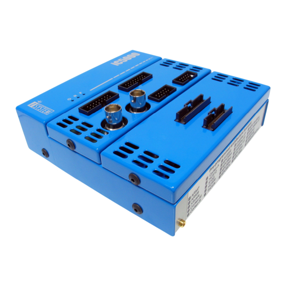
- Page 2 The iC5000 base unit is the heart of the iC5000 on-chip emulation system. There are three status LEDs on the iC5000 Base Unit. The status LEDs inform the user of the current status of the emulation system. Their meaning is: •...
- Page 3 Ordering code IC50020 iC5000 Base Unit in conjunction with the iC50020 Debug/Trace module is a universal on-chip emulation platform. Additionally, a connecting cable (40-pin flat cable), a target specific cable adapter and architecture specific license is required to debug the target based on a specific architecture.
- Page 4 40-pin flat cable used to connect architecture specific debug cable adapters to the iC5000 Debug/Trace module. 16-bit Nexus (IC50152) and 16-bit ETM (IC50115) cable adapters come with two flat cables (30-pin and 40-pin) pre-attached. With these, 40-pin flat cable, which is shipped next to the Debug/Trace module (IC50020), is not required.
- Page 5 The maximum voltage on the Current Sense probe is 60V. Nominal sampling rate is 1MSPS. Connectors iC5000 I/O Module Connectors’ Pinout • 10-pin header for the System Port. • 16-pin header for 8 digital inputs. • 16-pin header for 8 digital outputs.
- Page 6 - despite the fact the iC5000 development system features already a high quality protection on all connecting signals by default.
- Page 7 Advanced functionalities such as trace, profiling and code coverage become available via trace license. Make sure that the target debug connector to which ic5000 system connects, exposes microcontroller trace port (ETM, Nexus, …) when trace functionality is required.
- Page 8 10/100M Ethernet and USB 1.1/2.0. It is recommended to use USB2.0 interface since it provides the fastest transfer from the iC5000 development system to the PC where winIDEA IDE runs. This will guarantee a maximum performance of the iC5000 development system.
- Page 9 The Emulator must be switched off and then on again in order for changes to take effect. Emulator’s MAC address is written on the same sticker where you will also find device serial number as it is shown on the next picture. © iSYSTEM, January 2012 9/41...
- Page 10 TCP Port, as entered above into the Emulator. Connect the Emulator to the Ethernet, if not already connected, and click on the ‘Test’ button. The communication should be up and running. • Configuration with Automatic Discovery Select the Hardware/Communication tab. © iSYSTEM, January 2012 10/41...
- Page 11 Please select another port, set it up in the Emulator and in winIDEA and try again. When the ping is not more required, stop it using the keyboard shortcut Control+C. If more Emulators are connected to the Ethernet and have the same IP set, only one will be active. Every Emulator must have a unique IP. © iSYSTEM, January 2012 11/41...
- Page 12 (noise, skew, crosstalk, reflections, ground bounce…), which are introduced either due to the high frequency trace clock & data, due to the bad target PCB design or a combination of both. IC5000 has the ability to compensate for these issues via Trace Line Calibration functionality, which allows shifting threshold voltage and clock phase at the capture time of the trace data.
- Page 13 Trace Line Calibration window – scan has been performed and applied. Higher frequency: Valid “Data eyes” shown on upper data signal and how the clock (lower) must be invalid area delayed. valid area recommended currently used © iSYSTEM, January 2012 13/41...
- Page 14 This section contains some guidelines, which should be considered during the target PCB design to ensure the correct operation of the trace port (ETM, Nexus,…) and the external trace tool (iC5000, iTRACE GT). Note that the quality and timing of the trace port signals to the external trace tool are critical for correct and reliable trace operation.
- Page 15 16 bit to 12 bit or from 12 bit to 4 bit reduces the Nexus information bandwidth. Note that possible port size varies depending on the target CPU. • IC50000-1 (ordering code) has higher trace storage bandwidth than IC50000. © iSYSTEM, January 2012 15/41...
- Page 16 Ordering code IC50111 This adapter is used to connect the iC5000 development system to the Cortex-M3 based target. It connects to Debug/Trace module (IC50020) on one side and to the target debug connector on the other side. It can be used for targets featuring 20-pin 2.54 pitch target debug connector with Cortex-M3 pinout.
- Page 17 Ordering code IC50111 This adapter is used to connect the iC5000 development system to the Cortex-M3 or ARM7/ARM9 based target. It connects to Debug/Trace module (IC50020) on one side and to the target debug connector on the other side. It can be used for targets featuring 20-pin 2.54 pitch target debug connector with ARM pinout.
- Page 18 IAPIN20ARM14TI ordering code. Make sure you don’t mix up Texas Instruments pinout with standard 14-pin 2.54mm ARM pinout (cable adapter IC50112). Double check the pinout of the target debug connector with the iC5000 cable adapter pinout before connecting iC5000 to the target for the first time.
- Page 19 Ordering code IC50112 IC50112 ARM Cable Adapter is used to connect the iC5000 development system to the ARM7/ARM9 based target. It connects to Debug/Trace module (IC50020) on one side and to the target debug connector on the other side. It can be used for targets featuring 14-pin 2.54 pitch target debug connector with ARM pinout.
- Page 20 Ordering code IC50113 IC50113 Cortex-M3 Adapter Board is used to connect the iC5000 development system to the Cortex-M3 based target. It connects to Debug/Trace module (IC50020) on one side and to the target debug connector on the other side. It can be used for targets featuring 20-pin 1.27mm pitch target debug connector with Cortex-M3 pinout.
- Page 21 Ordering code IC50113-AMP IC50113-AMP Cortex-M3 Cable Adapter is used to connect the iC5000 development system to the Cortex-M3 based target. It connects to Debug/Trace module (IC50020) on one side and to the target debug connector on the other side. It can be used for targets featuring 20-pin 1.27mm AMPMODU target debug connector with Cortex- M3 pinout.
- Page 22 Ordering code IC50114 This adapter is used to connect the iC5000 development system to the Cortex-M3 or ARM7/ARM9 based target. It connects to Debug/Trace module (IC50020) on one side and to the target debug connector on the other side. It can be used for targets featuring Mictor 38-pin target debug connector with ARM7/ARM9 ETM pinout.
- Page 23 Ordering code IC50115 Note: iC5000 Debug/Trace module (IC50020) revision D or newer is required to be able to connect and use this adapter. This adapter is used to connect the iC5000 development system to the Cortex-M3 or ARM7/ARM9 based target.
- Page 24 Ordering code IC50116 This adapter is used to connect the iC5000 development system to the Cortex-M3 based target. It connects to Debug/Trace module (IC50020) on one side and to the target debug connector on the other side. It can be used for targets featuring 10-pin 1.27mm pitch target debug connector with Cortex-M3 pinout.
- Page 25 Ordering code IC50130 This adapter is used to connect the iC5000 development system to Freescale ColdFire based target. It connects between the Debug/Trace module (IC50020) and the target debug connector. It can be used for targets featuring 26-pin 2.54mm pitch target debug connector with ColdFire pinout.
- Page 26 Ordering code IC50140 This adapter is used to connect the iC5000 development system to Freescale HCS08, HC12, HCS12, S12X or ColdFire V1 based target. It connects to Debug/Trace module (IC50020) on one side and to the target debug connector on the other side. It can be used for targets featuring 6-pin 2.54mm pitch target debug connector with BDM pinout.
- Page 27 Ordering code IC50150 This adapter is used to connect the iC5000 development system to Freescale MPC5xxx and ST SPC56 based target via JTAG debug interface. It connects to Debug/Trace module (IC50020) on one side and to the target debug connector on the other side. It can be used for targets featuring 14-pin 2.54 pitch target debug connector with MPC5xxx pinout.
- Page 28 Ordering code IC50151 This adapter is used to connect the iC5000 development system to Freescale MPC5xxx or ST SPC56 based target via Nexus debug interface. It connects to Debug/Trace module (IC50020) on one side and to the target debug connector on the other side. It can be used for targets featuring Mictor 38-pin target debug connector with MPC5xxx Nexus pinout.
- Page 29 Ordering code IC50152 Note: iC5000 Debug/Trace module (IC50020) revision D or newer is required to be able to connect and use this adapter. This adapter is used to connect the iC5000 development system to Freescale MPC5xxx or ST SPC56 based target via Nexus debug interface.
- Page 30 In order to use this feature, jumper J2 must be bridged and the ‘Force periodic Nexus SYNC’ option in the ‘Hardware/emulation Options/CPU Setup/Nexus’ tab must be checked. Refer to iSYSTEM ‘Freescale MPC5xxx & ST SPC56 Family On-Chip Emulation’ technical notes document for more details on the ‘Force periodic Nexus SYNC’...
- Page 31 Signal Signal direction MSEO0 V_DEBUG MSEO1 MDO0 MDO1 JCOMP MDO2 MDO3 EVTI EVTO MCKO JTAG_RST MDO4 RESET_OUT MDO5 MDO5 MDO7 MDO8 MDO9 MDO10 MDO11 MDO13 MDO12 MDO14 MDO15 50-pin Samtec ERF8 Nexus target connector pinout © iSYSTEM, January 2012 31/41...
- Page 32 Ordering code IC50153 This adapter is used to connect the iC5000 development system to the Freescale MPC6xx, MPC82xx, MobileGT, MPC7xx or MPC83xx based target via COP/JTAG debug interface. It connects to Debug/Trace module (IC50020) on one side and to the target debug connector on the other side. It can be used for targets featuring 16-pin 2.54 pitch target debug connector with Freescale COP pinout.
- Page 33 Ordering code IC50155 Note: iC5000 Debug/Trace module (IC50020) revision D or newer is required to be able to connect and use this adapter. This adapter is used to connect the iC5000 development system to Applied Micro PPC4xx based target via RISCTrace debug interface.
- Page 34 Ordering code IC50160 This adapter is used to connect the iC5000 development system to the Infineon XC166, XC2000 and TriCore based target via JTAG debug interface. It connects to Debug/Trace module (IC50020) on one side and to the target debug connector on the other side. It can be used for targets featuring 16-pin 2.54 pitch target debug connector with Infineon JTAG pinout.
- Page 35 Ordering code IC50161 This adapter is used to connect the iC5000 development system to the Infineon XC166, XC2000 and TriCore based target. It connects to Debug/Trace module (IC50020) on one side and to the target debug connector on the other side. It can be used for targets featuring 10-pin 1.27mm pitch target debug connector with Infineon DAP pinout.
-
Page 36: Reset Out
Ordering code IC50170 This adapter is used to connect the iC5000 development system to the Renesas 78K0R based target via Serial debug interface. It connects to Debug/Trace module (IC50020) on one side and to the target debug connector on the other side. It can be used for targets featuring 16-pin 2.54 pitch target debug connector with 78K0R pinout. - Page 37 Ordering code IC50175 This adapter is used to connect the iC5000 development system to the Renesas RL78 based target via Serial debug interface. It connects to Debug/Trace module (IC50020) on one side and to the target debug connector on the other side. It can be used for targets featuring 14-pin 2.54 pitch target debug connector with RL78 pinout.
- Page 38 IC50171 This adapter is used to connect the iC5000 development system to the Renesas V850 based target. It connects to Debug/Trace module (IC50020) on one side and to the target debug connector on the other side. It can be used for targets featuring 20-pin 2.54 pitch target debug connector with V850 pinout.
- Page 39 IC50172 This adapter is used to connect the iC5000 development system to the Renesas V850 based target. It connects to Debug/Trace module (IC50020) on one side and to the target debug connector on the other side. It can be used for targets featuring 26-pin KEL target debug connector with V850 pinout.
- Page 40 IC50190 This adapter is used to connect the iC5000 development system to the ST STM8 based target. It connects to the Debug/Trace module (IC50020) on one side and to the target debug connector on the other side. It can be used for targets featuring 4-pin ERNI target debug connector with the STM8 pinout.
-
Page 41: Troubleshooting
It contains all the information related to the debugging including some troubleshooting tips. Disclaimer: iSYSTEM assumes no responsibility for any errors which may appear in this document, reserves the right to change devices or specifications detailed herein at any time without notice, and does not make any commitment to update the information herein.
Need help?
Do you have a question about the iC5000 and is the answer not in the manual?
Questions and answers