iSystem iC5000 User Manual
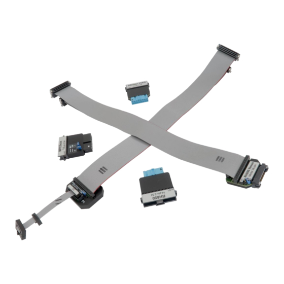
Debug adapters
Hide thumbs
Also See for iC5000:
- Hardware reference manual (69 pages) ,
- User manual (16 pages) ,
- User manual (20 pages)
Table of Contents
Advertisement
Quick Links
- 1 Introduction
- 2 20-Pin 2.54Mm Arm Debug Adapter
- 3 20-Pin 2.54Mm Cortex Debug Adapter
- 4 10-Pin 1.27Mm Cortex Debug Adapter
- 5 14-Pin 2.54Mm Mpc5Xxx Debug Adapter
- 6 Ecu14 Jtag 10-Pin 1.27Mm Adapter
- 7 16-Pin 2.54Mm Infineon Jtag Debug Adapter
- 8 14-Pin 2.54Mm Renesas Rh850 Debug Adapter
- Download this manual
Advertisement
Table of Contents

Related Manuals for iSystem iC5000


Summary of Contents for iSystem iC5000
- Page 1 & iC5700 Debug Adapters V1.6 User Manual...
- Page 2 This document and all documents accompanying it are copyrighted by iSYSTEM AG and all rights are reserved. Duplication of these documents is allowed for personal use. In all other cases, written consent from iSYSTEM is required. Copyright iSYSTEM AG.
-
Page 3: Table Of Contents
Contents Introduction ..........................1 20-pin 2.54mm ARM Debug Adapter ................... 2 Texas Instruments 14-pin 2.54mm Adapter ................3 20-pin 2.54mm Cortex Debug Adapter ..................4 14-pin 2.54mm ARM Debug Adapter ................... 5 20-pin 1.27mm AMP Cortex Debug Adapter ................6 38-pin Mictor ARM ETM 16-bit D. -
Page 4: Introduction
Introduction The iC5000 and the iC5700 BlueBox adapt to the specific target architecture and target debug connector through a dedicated debug adapter. This document provides detailed information on all debug adapters which are used in conjunction with the iC5000 and the iC5700 BlueBox, and are supported by winIDEA 9.17.0... -
Page 5: 20-Pin 2.54Mm Arm Debug Adapter
Ordering code IC50111-1 This debug adapter is used to connect the iC5000 and the iC5700 BlueBox to the Cortex-A, the Cortex-R, the ARM7 and the ARM9 based target. It’s used to connect to the embedded target featuring a 20-pin 2.54 mm pitch target debug connector with the ARM pinout. -
Page 6: Texas Instruments 14-Pin 2.54Mm Adapter
Texas Instruments 14-pin 2.54mm Adapter Embedded targets based on Texas Instruments (TI) ARM microcontroller can feature Texas Instruments ARM 14-pin target debug connector with the TI the proprietary pinout. An adapter connecting at the end of the 20-pin 2.54mm ARM Debug Adapter is available for Texas Instruments ARM 14-pin pinout and must be ordered separately under the IAPIN20ARM14TI ordering code. -
Page 7: 20-Pin 2.54Mm Cortex Debug Adapter
Ordering code IC50111-2 This debug adapter is used to connect the iC5000 and the iC5700 BlueBox to the Cortex-M based target. It’s used to connect to the embedded target featuring a 20-pin 2.54 mm pitch target debug connector with the ARM pinout. -
Page 8: 14-Pin 2.54Mm Arm Debug Adapter
Ordering code IC50112 This debug adapter is used to connect the iC5000 and the iC5700 BlueBox to the Cortex-A, the Cortex-R, the ARM7 and the ARM9 based target. It’s used to connect to the embedded target featuring a 14-pin 2.54 mm pitch target debug connector with the ARM pinout. -
Page 9: 20-Pin 1.27Mm Amp Cortex Debug Adapter
Ordering code IC50113-AMP This debug adapter is used to connect the iC5000 and the iC5700 BlueBox to the Cortex-M based target. It’s used to connect to the embedded target featuring a 20-pin 1.27mm AMPMODU target debug connector with the Cortex-M pinout. -
Page 10: 38-Pin Mictor Arm Etm 16-Bit D. Adapter
Ordering code IC50115 This debug adapter is used to connect the iC5000 and the iC5700 BlueBox to the Cortex-A, the Cortex-R, the ARM7 and the ARM9 based target. It’s used to connect to the embedded target featuring a 38-pin Mictor target debug connector with the ARM ETMv1 or the ARM ETMv3 pinout. - Page 11 Blue colored signals are trace signals. When connecting the BlueBox to the new embedded target for the first time, double check that the debug adapter pinout matches with the target debug connector. Note that a mismatch can result in a hardware failure. The following pinout is valid on the target side for the ARM ETMv3: Signal direction Signal...
-
Page 12: Texas Instruments 60-Pin Mipi Adapter
Ordering code IAMIC38MIPI60TMS570 The iC5000 and the iC5700 can trace up to 16 trace data lines. The target microcontroller has to be configured for 16-bit trace port operation if the target features 60-pin MIPI connector with 32 data trace lines connected. - Page 13 The following pinout is valid on the target side: Signal direction Signal Signal Signal direction VTref nSRST RTCK nTRST_PD nTRST_PU TRACECLK TRACECTL TRACEDATA0 TRACEDATA1 TRACEDATA2 TRACEDATA3 TRACEDATA4 TRACEDATA5 TRACEDATA6 TRACEDATA7 TRACEDATA8 TRACEDATA9 TRACEDATA10 TRACEDATA11 TRACEDATA12 TRACEDATA13 TRACEDATA14 TRACEDATA15 60-pin MIPI target pinout Blue colored signals are trace signals.
-
Page 14: 10-Pin 1.27Mm Cortex Debug Adapter
Ordering code IC50116-2 This debug adapter is used to connect the iC5000 and the iC5700 BlueBox to the Cortex-M based target. It’s used to connect to the embedded target featuring a 10-pin 1.27mm target debug connector with the Cortex-M pinout. - Page 15 connector. Matching part on the target is Samtec SHF-105-01-L-D or Samtec FTSH-105-01-F- DV-K (connector without the frame at the side). Recommendation for the target side connector is the FTSH-105-01-F-DV-K connector, which matches the connector with and without the strain relief option. Robust and less prone to fail...
- Page 16 (e.g. 10 cm) since the quality of electrical signals degrades with prolonging the cable. iSYSTEM gives no assurance for BlueBox operation with this cable. The cable is meant to be used only for boundary cases where BlueBox cannot be connected to the target hardware through the standard debug adapter, for example due to the physical obstacles of the target system.
-
Page 17: 10-Pin 1.27Mm Custom Cortex D. Adapter
Ordering code IC50116-CUST2 This debug adapter is used to connect the iC5000 and the iC5700 BlueBox to the Cortex-M based target. It’s used to connect to the embedded target featuring a 20-pin 1.27mm target debug connector with the custom Cortex-M pinout. Optionally connecting the RTCK or the JTAG TRST to pin 7 (KEY pin otherwise) makes this debug adapter distinct from the IC50116-2 debug adapter. -
Page 18: 20-Pin 1.27Mm Cortex Debug Adapter
Ordering code IC50118-2 This adapter is used to connect the iC5000 and the iC5700 development system to the Cortex- M based target. It’s used to connect to the embedded target featuring a 20-pin 1.27mm target debug connector with the Cortex-M pinout. - Page 19 20-pin 1.27mm Cortex-M Debug Adapter features resettable fuses on pins 1, 2, 4, 6, 8 and 10. These protect debug signals against overcurrent and cycle back to a conductive state after the excessive current fades away. Signals on pins 12, 14, 16, 18 and 20 are protected via 100 ohm serial resistors.
- Page 20 Robust, less prone to fail...
- Page 21 (e.g. 10 cm) since the quality of electrical signals degrades with prolonging the cable. iSYSTEM gives no assurance for BlueBox operation with this cable. The cable is meant to be used only for boundary cases where BlueBox cannot be connected to the target hardware through the standard debug adapter, for example due to the physical obstacles of the target system.
-
Page 22: 20-Pin 1.27 X 2.54Mm Compact Ti-20 D. Adapter
Ordering code IC50119 This debug adapter is used to connect the iC5000 and the iC5700 BlueBox to the Cortex-M based target. It’s used to connect to the embedded target featuring a 20-pin 1.27 x 2.54 mm target debug connector with the Compact TI-20 pinout. - Page 23 20-pin 1.27 x 2.54 mm Compact TI-20 Debug Adapter features resettable fuses on all pins except for pin 9, 13, 14, 17-19. These fuses protect debug signals against overcurrent and cycle back to a conductive state after the excessive current fades away. Signals on pins 13, 14, 17-19 are protected via 100 ohm serial resistors.
-
Page 24: 16-Pin 1.27Mm Custom Arm Debug Adapter
Ordering code IC50120 This debug adapter is used to connect the iC5000 and the iC5700 BlueBox to the Cortex-M based target. It’s used to connect to the embedded target featuring a 16-pin 1.27 mm pitch target debug connector with the custom ARM pinout. -
Page 25: 14-Pin 2.54Mm Mpc5Xxx Debug Adapter
Ordering code IC50150 This debug adapter is used to connect the iC5000 and the iC5700 BlueBox to the Cortex-M based target. It’s used to connect to the embedded target featuring a 14-pin 2.54mm pitch target debug connector with MPC5xxx/SPC5 pinout. - Page 26 In order to use this feature, the jumper J2 must be bridged and the ‘Force periodic Nexus SYNC’ option in the ‘Hardware/emulation Options/CPU Setup/Nexus’ tab must be checked. Refer to iSYSTEM ‘Freescale MPC5xxx & ST SPC56 Family On-Chip Emulation’ technical notes document for more details on the ‘Force periodic Nexus SYNC’ option use.
-
Page 27: Ecu14 Jtag 10-Pin 1.27Mm Adapter
Jumper J2 was introduced with the debug adapter revision C1. Previous versions A1, A2, B1 and D1 don’t provide this jumper. The debug adapter connects to the target via a 14-pin 2.54 mm connector, for example Yamaichi FAS-1401-2101-2-0BF. A target should feature a matching part, for example WÜRTH ELEKTRONIK: 612 014 216 21. - Page 28 Jumper J2 The jumper J2 is optional and by default not populated. It connects 10k pull-down resistor to the USERIO pin when bridged. The jumper has been introduced for a custom target, where the target watchdog gets disabled during the debugging, when low level at the USERIO signal (target debug connector pin 7) is detected.
-
Page 29: 38-Pin Mictor Mpc5Xxx Nexus 16-Bit D. Adapter
Ordering code IC50152-12 This debug adapter is used to connect the iC5000 and the iC5700 BlueBox to Freescale MPC5xxx or ST SPC5 based target. It’s used to connect to the embedded target featuring a 38- pin Mictor target debug connector with the MPC5xxx Nexus pinout. - Page 30 Typically there is no need to use the ‘Force periodic Nexus SYNC’ functionality unless a specific application code is traced, which does not generate messages containing absolute program counter information. As long as the user has no problems with the trace use, it is recommended to keep the jumper J2 disconnected.
-
Page 31: 50-Pin Erf8 Mpc5Xxx Nexus Adapter
50-pin ERF8 MPC5xxx Nexus Adapter Ordering code IAMIC38SAM50MPC IAMIC38SAM50MPC adapter Some targets based on Freescale Qorivva Power Architecture or PX Series Power Architecture microcontroller(s) (e.g. MPC5675K) can also feature a 50-pin Samtec ERF8 connector for the Nexus debug interface instead of the popular 38-pin Mictor connector. In this case, the IAMIC38SAM50MPC adapter is connected to the target first and then used in conjunction with the 38-pin Mictor MPC5xxx Nexus 16-bit Debug Adapter. - Page 32 The following pinout is valid on the target side: Signal direction Signal Signal Signal direction MSEO0 VTREF MSEO1 MDO0 MDO1 nTRST MDO2 MDO3 EVTI EVTO MCKO nSRST MDO4 MDO5 MDO6 MDO7 MDO8 MDO9 MDO10 MDO11 MDO13 MDO12 MDO14 MDO15 50-pin Samtec ERF8 MPC5xxx Nexus target pinout Blue colored signals are trace signals.
-
Page 33: 50-Pin Erf8 Mpc5Xxx Nexus 16-Bit D. Adapter
50-pin ERF8 MPC5xxx Nexus 16-bit D. Adapter Ordering code IC50156 This debug adapter is used to connect the iC5000 and the iC5700 BlueBox to Freescale MPC5xxx or ST SPC56 based target featuring a 50-pin Samtec ERF8 target debug connector with the MPC5xxx Nexus pinout. - Page 34 Typically there is no need to use the ‘Force periodic Nexus SYNC’ functionality unless a specific application code is traced, which does not generate messages containing absolute program counter information. As long as the user has no problems with the trace use, it is recommended to keep the jumper J2 disconnected.
-
Page 35: 16-Pin 2.54Mm Infineon Jtag Debug Adapter
16-pin 2.54mm Infineon JTAG Debug Adapter Ordering code IC50160 This debug adapter is used to connect the iC5000 and the iC5700 BlueBox to Infineon TriCore and XC2000/XC166 based target featuring a 16-pin 2.54mm pitch target debug connector with Infineon JTAG pinout. -
Page 36: 10-Pin 1.27Mm Tricore Ecu14 Debug Adapter
This connector has been defined by Bosch and supports the JTAG and the DAP debug interface. This debug adapter is used to connect the iC5000 and the iC5700 BlueBox to Infineon TriCore and XC2000/XC166 based target featuring a 10-pin 1.27mm pitch target debug connector with Bosch ECU14 pinout. - Page 37 10-pin 1.27mm TriCore ECU14 Debug Adapter features resettable fuses on all connected pins. These protect debug signals against overcurrent and cycle back to a conductive state after the excessive current fades away. Mandatory pins on the microcontroller side are the TMS, the TDO, the TDI, the ~TRST, the TCLK and the ~RESET.
-
Page 38: 10-Pin 1.27Mm Tricore Medc17 Debug Adapter
This connector has been defined by Bosch and supports the JTAG debug interface only. This debug adapter is used to connect the iC5000 and the iC5700 BlueBox to Infineon TriCore and XC2000/XC166 based target (via the JTAG debug interface) featuring a 10-pin 1.27mm pitch target debug connector with Bosch MEDC17 pinout. -
Page 39: 6-Pin 2.54Mm Infineon I C Debug Adapter
C Debug Adapter Ordering code IC50162 This debug adapter is used to connect the iC5000 and the iC5700 BlueBox to Infineon SP37/SP40 based target featuring a 6-pin 2.54mm pitch target debug connector with Infineon I2C pinout. The debug adapter connects to the 25cm 40-pin ribbon cable coming from the BlueBox and to the target debug connector on the other side. - Page 40 download, first user flash is erased, then the application code programmed into the flash and at the end the complete flash is read back. This last step is required since the code memory can be no longer read once the MCU is in the debug mode. Beside of the user flash, the SP41 has also the Firmware ROM which cannot be read by the debugger.
-
Page 41: 10-Pin 1.27Mm Infineon Dap2 Wide D. Adapter
10-pin 1.27mm Infineon DAP2 Wide D. Adapter Ordering code IC50163-2 This debug adapter is used to connect the iC5000 and the iC5700 BlueBox to Infineon TriCore and XC2000/XC166 based target featuring a 10-pin 1.27mm pitch target debug connector with Infineon DAP pinout. - Page 42 10-pin 1.27mm Infineon DAP Debug Adapter features resettable fuses on pins 1, 2, 3, 4, 5, 6, 8, 9 and 10. These fuses protect debug signals against overcurrent and cycle back to a conductive state after the excessive current fades away. The debug adapter connects to the target through one of the two 10-pin 1.27mm connectors.
- Page 43 Robust and less prone to fail If the 10-pin 1.27 mm pitch cable gets damaged, it can be ordered as a spare part under the ordering code IA10PIN10PIN127.
- Page 44 (e.g. 10 cm) since the quality of electrical signals degrades with prolonging the cable. iSYSTEM gives no assurance for BlueBox operation with this cable. The cable is meant to be used only for boundary cases where BlueBox cannot be connected to the target hardware through the standard debug adapter, for example due to the physical obstacles of the target system.
-
Page 45: 22-Pin Erf8 Dap2 Debug Adapter
Ordering code IC50164 This debug adapter is used to connect the iC5000 and the iC5700 BlueBox to Infineon Aurix based target providing Aurora trace interface along the DAP debug interface and featuring a 22-pin Samtec ERF8 target debug connector with the 22-pin ERF8 Aurix target pinout. - Page 46 When connecting the BlueBox to the new embedded target for the first time, double check that the debug adapter pinout matches with the target debug connector. Note that a mismatch can result in a hardware failure. 22-pin ERF8 DAP2 Debug Adapter features resettable fuses on pins 2, 4, 5, 6, 10, 11, 12, 17 and 22.
-
Page 47: 20-Pin 2.54Mm Renesas V850/Rh850 D. Adapter
20-pin 2.54mm Renesas V850/RH850 D. Adapter Ordering code IC50171 This debug adapter is used to connect the iC5000 and the iC5700 BlueBox to Renesas RH850 based target featuring a 20-pin 2.54 mm pitch target debug connector with the V850/RH850 pinout. -
Page 48: 14-Pin 2.54Mm Renesas Rh850 Debug Adapter
Ordering code IC50176 This debug adapter is used to connect the iC5000 and the iC5700 BlueBox to Renesas RH850 based target featuring a 14-pin 2.54 mm pitch target debug connector with the RH850 pinout. The debug adapter connects to the 25cm 40-pin ribbon cable coming from the BlueBox and to the target debug connector on the other side. -
Page 49: 10-Pin 1.27Mm Renesas Rh850 Debug Adapter
10-pin 1.27mm Renesas RH850 Debug Adapter Ordering code IC50176-EPS This debug adapter is used to connect the iC5000 and the iC5700 BlueBox to Renesas RH850 based target featuring a 10-pin 1.27 mm pitch target debug connector with the RH850 proprietary (EPS) pinout. - Page 50 cautiously or just connected/disconnected too many times. This connector should be used when the target doesn’t provide the matching target connector for the “strain relief” type connector. Matching part on the target is Samtec SHF-105-01-L-D or Samtec FTSH-105-01-F- DV-K (connector without the frame at the side). Recommendation for the target side connector is the FTSH-105-01-F-DV-K connector, which matches the connector with and without the strain relief option.
- Page 51 (e.g. 10 cm) since the quality of electrical signals degrades with prolonging the cable. iSYSTEM gives no assurance for BlueBox operation with this cable. The cable is meant to be used only for boundary cases where BlueBox cannot be connected to the target hardware through the standard debug adapter, for example due to the physical obstacles of the target system.
-
Page 52: 38-Pin Mictor Rh850 Nexus 16-Bit D. Adapter
38-pin Mictor RH850 Nexus 16-bit D. Adapter Ordering code IC50177 This debug adapter is used to connect the iC5000 and the iC5700 BlueBox to Renesas RH850 based target featuring a 38-pin Mictor target debug connector with the RH850/F1H Nexus pinout. - Page 53 Blue colored signals are trace signals. When connecting the BlueBox to the new embedded target for the first time, double check that the debug adapter pinout matches with the target debug connector. Note that a mismatch can result in a hardware failure. Mictor 38-pin Renesas RH850 Nexus 16-bit Debug Adapter features resettable fuses on pins 9, 11, 12, 15, 17, 19, 21, 37.
- Page 54 While iSYSTEM reserves the right to make changes to its products and/or the specifications detailed herein, it does not make any representations or commitments to update this document.
Need help?
Do you have a question about the iC5000 and is the answer not in the manual?
Questions and answers