Table of Contents
Advertisement
Quick Links
Advertisement
Table of Contents

Related Manuals for Dentsply Sirona X-Smart


Summary of Contents for Dentsply Sirona X-Smart
- Page 1 User Manual...
- Page 2 PAGE INTENTIONALLY LEFT BLANK 2/48 B EN XS00 DFU WEB / Rev.08 / 01-2018 (Old ZF 190270.EN)
-
Page 3: Table Of Contents
Table of contents Table of contents Introduction ......... . . 6 Indications . - Page 4 Table of contents Main Directions For Use ....... . . 19 Charge (if batteries are used) .
- Page 5 Table of contents Error Code ......... . . 35 Troubleshooting .
-
Page 6: Introduction
(or other electrical equipment) and has been cautioned against the use of small electrical appliances (such as electric shavers, ® hair dryers, etc.) it is recommended to not use the X-Smart This motor should not be used for severe curved root canal preparation. ®... - Page 7 When installing the device, leave approximately 10cm around the control unit for easy access to the inlet and the power cord. • Portable and mobile radio frequency (RF) communications ® equipment can affect the proper functioning of X-Smart ® • The X-Smart requires special precautions as regards...
-
Page 8: Precautions
• The appliance must only be used with the manufacturer's original accessories. • Use the Dentsply Sirona AC adapter for this product. Never use any other AC adapters. • The RPM number indicates true instrument speed when the appropriate reduction rate is selected. Make sure the selected reduction matches the ratio of the contra angle handpiece. -
Page 9: Notice
Introduction Notice • Fully-charged rechargeable batteries generally discharge gradually over time even though the motor handpiece is not used. It is recommended to recharge the batteries just before use. • When the motor handpiece stops automatically by detecting a low battery voltage, turning on the power again after a while may not detect the low voltage immediately. -
Page 10: Classifications Of Equipment
• Degree of safety of application in the presence of a flammable anesthetic mixture with air or with oxygen or nitrousoxide: ® - X-Smart complies to IEC60601-1 safety standard and the requirement of CE Marking of Conformity. • Mode of operation: - Continuous operation. -
Page 11: Contents
Contents CONTENTS Before use, please refer to the packaging labels. PRODUCT MAIN SPECIFICATIONS ® control unit: X-Smart Rated input DC20V 0.5 A Output DC7V 0.4 A Charging time 5 hours approx. Dimensions W98 x D152 x H139 mm Weight 456 g... -
Page 12: Product Description
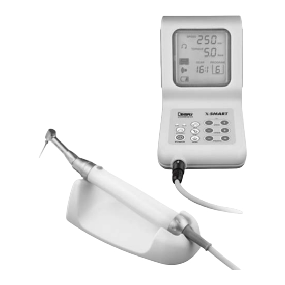
Product Description PRODUCT DESCRIPTION Option Fig. 1 Control Unit Operation panel • Fig. 2 "Operation Panel and LCD Panel". LCD Panel • Fig. 2 “Operation Panel and LCD Panel.” • Error codes are displayed. Power Cord Connector Foot Pedal Connector Motor Handpiece Connector AC Adapter Motor Handpiece... -
Page 13: Operation Panel And Lcd Panel
Product Description Operation Panel and LCD Panel (LCD Panel) (Operation Panel) AC IN Reverse Charge Speed Auto Reverse Torque Power Program Memorize Gear Ratio Fig. 2 Power • Holding down the POWER key for more than one second turns on the power and the LCD panel lights. -
Page 14: Torque
Product Description Torque • The torque limit values can be adjusted. • If the torque is to exceed the upper limit or fall below the lower limit, the alarm sounds. The present torque limit value is displayed. The unit is (Ncm). -
Page 15: Gear Ratio
Product Description Gear Ratio • A gear ratio can be selected by this key. If the correct gear ratio is selected according to the contra angle head in use, an adequate rotation speed and torque limit value can be set. •... -
Page 16: Memo
Product Description Memo Press this key if you want to change the present program setting (rotation speed, torque limit value, gear ratio, auto reverse mode) and these changes will be memorized (see Program). 4.10 CHARGE Lamp (Orange) This lamp lights or flashes while the batteries are being charged or in the refresh mode, (see Refresh) and in an error condition, 7.3 Battery... -
Page 17: Bar Display
How to connect each part 4.12 Bar Display It displays the bar graph which shows the degree of load applied to the motor while the file is in motion. HOW TO CONNECT EACH PART Connecting Motor Handpiece Align the mark of the cord plug of the motor handpiece with the ▲... -
Page 18: Connecting Ac Adapter
How to connect each part Connecting AC Adapter Securely insert the jack of the AC adapter into the power connector with mark of the jack cast down (see Fig. Adapter connection Fig. 4 Connecting Foot Pedal (Optional) Securely insert the plug of the foot pedal (Optional) into the foot pedal connector with the ▲... -
Page 19: Main Directions For Use
Main Directions For Use MAIN DIRECTIONS FOR USE Reverse Speed AC IN Charge Torque Auto Reverse Power Program Memorize Gear Ratio Fig. 6 Charge (if batteries are used) Securely insert the plug of the AC adapter into a power supply. The AC IN lamp lights in green. - Page 20 Main Directions For Use CAUTION • Connect to AC120 V or AC230 V power supply only. Otherwise, malfunction will occur. • Since the AC IN lamp lights to indicate that the supply power is on, it does not go out even after a charge is completed. See the CHARGE lamp to check the charging conditions.
-
Page 21: Changing The Contra Angle
Main Directions For Use Changing the Contra Angle • The contra angle can be connected with the motor handpiece at 6 adjustable head positions. Align the positioning pins of the contra angle head with the positioning slots of the motor handpiece and insert the head until they click. -
Page 22: Preparatory Operations
Main Directions For Use CAUTION • When attaching and detaching the file, turn the power off beforehand. • After the file is locked in place, lightly pull out the file to make sure the file is locked. • Always clean the shank of the file to be installed. Allowing dirt to enter the chuck could cause loss of concentricity and deterioration of chucking force. -
Page 23: Operation
Main Directions For Use Operation • If you press the ON/OFF button ON/OFF Button briefly, the motor handpiece starts. If you re-press the button, it stops. • If you hold down the ON/OFF button for more than one second, the motor handpiece starts while the button is pressed. - Page 24 Main Directions For Use AUTO REVERSING The motor handpiece rotates in reverse. When a load is removed, the motor handpiece returns to normal rotation (forward rotation) automatically. Further Loading Load within the If the load is kept applied, the file beyond the preset Torque Limit Value will rotate in reverse.
-
Page 25: Completion Of Medical Treatment
Main Directions For Use Notice • When the reverse rotation (R) is set, this auto reverse function is not activated. • When the batteries go down (when the remaining amount of the batteries mark indicates “ ”), the actual load may not reach the preset torque limit value. -
Page 26: Additional Directions For Use
Additional Directions For Use ADDITIONAL DIRECTIONS FOR USE Program This product is programmed in advance with 1 to 9 programs according to various files to be used. You can change any preset values and have them saved to your desired settings (rotation speed, torque limit value, gear ratio and auto reverse mode). -
Page 27: Initialization Of Program (Factory-Set Configuration)
Additional Directions For Use Initialization of Program (Factory-set configuration) The program can be returned to the original state configured at the time of factory shipment, if setup becomes confusing. Turn off the power, when the power is on. Connect the AC adapter and confirm that the AC IN lamp lights up. Hold down the POWER key for more than one second, while pressing the AUTO REVERSE key and MEMORIZE key at the same time. - Page 28 Additional Directions For Use The alarm sounds for a length of time, and the refresh mode is activated. At this time, the remaining amount of the batteries mark on the LCD panel is animated in the direction opposite to display at the time of charging.
-
Page 29: Calibration
Additional Directions For Use Calibration This function is to decrease fluctuation in the rotation speed of the motor handpiece and the difference in torque by the contra angle. Calibration is recommended when using a new/other contra-angle or after an extended period of operation, as the running properties can change with usage, cleaning and sterilization. -
Page 30: Alarm Sound Volume Control
Additional Directions For Use Alarm Sound Volume Control The alarm sound volume can be controlled by using “BIG VOLUME, SMALL VOLUME and LIMITED OFF”. With “LIMITED OFF”, the alarm sounds with a small sound volume at the time of confirmation and error, while it does not sound at the time of reverse rotation and attainment of the torque limit value. -
Page 31: Cleaning
Cleaning CLEANING Lubricating Contra Angle • Lubricate the contra angle head Contra Angle Spray Nozzle only. Head • After each use and/or before each autoclaving. • Screw the spray nozzle onto the Spray can by approx. 10 turns. • Insert the spray nozzle into the rear part of the contra angle head and lubricate the head for 2-3 seconds. -
Page 32: Sterilization
Sterilization CAUTION • Do not lubricate the motor section of the motor handpiece. • To clean the motor handpiece, do not use any solvent such as benzine and/or a thinner. • Before mounting the lubricated contra angle head to the motor handpiece, wipe off extra oil. -
Page 33: Changing Batteries
(refer to the “Changing Batteries”). When replacing, be sure to observe the following “ CAUTIONS ON CHANGING BATTERIES”. Note that Dentsply Sirona shall not be held liable for any malfunction or failure resulting from your not following the “... -
Page 34: Changing Batteries
Changing batteries 10.1 Changing Batteries Battery cover Fig. 13 Turn off the power. Remove the AC adapter. Remove the batteries after sliding the battery cover on the back of the control unit in the direction of the arrow. (Fig. CAUTION Ensure removal of the AC adapter before changing batteries, as it may cause a malfunction. -
Page 35: Error Code
Error Code CAUTION In case of difficult to insert the connector onto the battery, the polarity may be incorrect. Do not insert it by force. Close the battery cover. Ensure you charge the batteries before use. NOTICE The used nickel metal hydride batteries are recyclable, but their disposal may sometimes not be permitted by the country. - Page 36 Error Code Error Error Cause Check / Remedy code Self-Check Malfunction of Contact your dealer. error circuit. The motor handpiece is locked. Overcurrent Remove load. (at the time of the auto reverse mode). Malfunction of Overvoltage Contact your dealer. circuit. During High load was rotation of...
-
Page 37: Troubleshooting
If none of these are applicable or the trouble is not remedied even after action has been taken, the product may have failed. Contact your dealer. ® Control unit and AC adapter X-Smart Problem Cause Solution The AC adapter is not Check the connected. - Page 38 Troubleshooting Problem Cause Solution The AC adapter is not Check the connected. connection. The plug of the AC adapter is not inserted Check the into the outlet, or there is connection. AC IN lamp does not no electricity in the outlet. light.
- Page 39 Troubleshooting ® motor handpiece X-Smart Problem Cause Solution The motor handpiece Check the cord is not connected. connection. The foot pedal (Optional) Check the The motor handpiece is not connected. connection. does not rotate. There is a break in the motor handpiece or the Contact your dealer.
-
Page 40: Warranty
® The X-Smart control unit, motor handpiece and contra angle are warranted for 24 months from the date of purchase. The accessories (battery, stand) are not covered under the warranty. In... -
Page 41: Identification Of Symbols
Identification of Symbols IDENTIFICATION OF SYMBOLS Serial number Batch code / Lot number Manufacturer Class II equipment Type B applied part Caution Follow instructions for use Recycling : PLEASE DO NOT THROW AWAY! : this product and all its components must absolutely be recycled through your supplier Direct current Input current... - Page 42 Identification of Symbols 130°C To identify fuse boxes or their location For indoor use only TUV Rheinland of North America is a Nationnaly Recognized Testing Laboratory (NRTL) in the United States and is accredited by the Standards Council of Canada to certify electro-medical products with Canadian National Standards Marking on the outside of Equipment or Equipment parts that include RF transmitters or that apply RF electromagnetic energy...
- Page 43 Appendix Electromagnetic Emission and Immunity Guidance and manufacturer’s declaration - electromagnetic emissions The device is intended for use in the electromagnetic environment specified below. The customer or the user or the device should ensure that it is used in such an environment.
- Page 44 Guidance and manufacturer's declaration - electromagnetic immunity The device is intended for use in the electromagnetic environment specified below. The customer or the user of the device should ensure that it is used in such an environment. IEC 60601 test Electromagnetic Immunity test Compliance level...
- Page 45 Guidance and manufacturer's declaration - electromagnetic immunity The device is intended for use in the electromagnetic environment specified below. The customer or the user of the device should ensure that it is used in such an environment. Immunity IEC 60601 Compliance Electromagnetic environment - guidance test...
- Page 46 Field strengths from fixed transmitters, such as base stations for radio (cellular/ cordless) telephones and land mobiles radios, amateur radio, AM and FM radio broadcast and TV broadcast cannot be predicted theoretically with accuracy. To assess the electromagnetic environment due to fixed RF transmitters, an electromagnetic site survey should be considered.
- Page 47 Recommended separation distances between portable and mobile RF communications equipment and the device The device is intended for use in an electromagnetic environment in which radiated RF disturbances are controlled. The customer or the user of the device can help prevent electromagnetic interference by maintaining a minimum distance between portable and mobile RF communications equipment (transmitters) and the device as recommended below, according to the maximum output power of the communications...
- Page 48 dentsplysirona.com Maillefer Instruments Holding Sàrl Chemin du Verger 3 CH-1338 Ballaigues 0086 Switzerland email: endo@dentsplysirona.com B EN XS00 DFU WEB / Rev.08 / 01-2018 (Old ZF 190270.EN)
Need help?
Do you have a question about the X-Smart and is the answer not in the manual?
Questions and answers