Table of Contents
Advertisement
Advertisement
Table of Contents

Related Manuals for AUTEC Modular series


Summary of Contents for AUTEC Modular series
- Page 1 Modular Series Master/Slave system Master/Master system User Manual...
- Page 3 Modular Series Master/Slave system Master/Master system User Manual...
- Page 4 Follow the indications and warnings given by the machine producer regarding the machine on which the radio remote control is installed. If this manual is lost or damaged, ask for a copy from Autec. Please specify the serial number of the related radio remote control.
-
Page 5: Table Of Contents
Conventions..................2 System description ................2 Conformity ..................4 Risk analysis ..................5 Documentation..................5 Modular Series technical data..............6 Frequencies ..................6 Transmitting units ................7 Description of MK12 and MK10 ............... 7 Description of MJ .................. 8 Warnings for the use of the transmitting units .......... 9 Warnings for the maintenance of the transmitting units ...... -
Page 6: Introduction
IMPORTANT TEXTS abcd… System description Industrial radio remote controls of the Modular series are used to control machines from a dis- tance. Each industrial radio remote control is made up of at least one portable transmitting unit, from which the user can remotely control the machine, and at least one receiving unit installed on board the machine itself. - Page 7 The transmitting unit UTX-M can work: - in single mode, namely it can work with either of the two receiving units (either URX-1 or URX- - in tandem mode, namely it can work with both receiving units simultaneously The transmitting unit UTX-S can only work in single mode with the receiving unit URX-2. The receiving unit URX-1 can only be controlled by the transmitting unit UTX-M.
-
Page 8: Conformity
- one is used for the transmitting unit UTX-S, and can be decoded by both receiving units Conformity Each Modular series radio remote control is in conformity with FCC Rules (Part 90 for the transmitting unit and Part 15 for the receiving unit). -
Page 9: Risk Analysis
The machine producer and/or the person who decides upon radio remote control use and installation is responsible for this analysis. Autec cannot be held responsible if the risk analysis is not carried out correctly. When carrying out risk analysis for the machine, the following aspects regarding the radio re- mote control have to be considered: 1.working application... -
Page 10: Modular Series Technical Data
Frequencies The radio frequency of Autec radio remote controls is included in the group of frequen- cies permitted by regulations that are current at the moment of radio remote control entry onto the market. -
Page 11: Transmitting Units
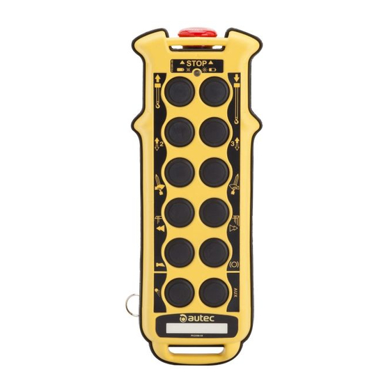
TRANSMITTING UNITS Description of MK12 and MK10 (photos shown below only represent two of the possible configurations) MK12 MK10 starting keyswitch STOP pushbutton signalling LED pushbuttons technical data plate, identification pushbutton plate (in the battery housing) Actuator (if present) toggle switch START pushbutton keyswitch selector battery... -
Page 12: Description Of Mj
Climatic Temperature Relative Humidity Air Pressure conditions Class 4K4H Class 4K4H Class 4K4H Working -5°F to +130°F 86 kPa to 106 kPa 4% to 100% (0,9 g/m to 36 g/m (-20°C to +55°C) Class 1K5 Class 1K3 Class 1K4 Storage -40°F to + 160°F 86 kPa to 106 kPa 5% to 95% (1 g/m... -
Page 13: Warnings For The Use Of The Transmitting Units
OUS INJURY OR DEATH TO PERSONNEL AND DAMAGE TO EQUIPMENT. The user must always respect the following warnings: Autec, or its distributors, cannot be held responsible if the radio remote control is installed on applications other than those permitted and if used in irregular working conditions. -
Page 14: Receiving Unit
RECEIVING UNIT Description of the receiving unit cable gland (opt. plug) Drilling template identification plate 5.8” (148 mm) technical data plate 4.6” (116 mm) POWER ENABLE light 10” (253 mm) antenna 10” (253 mm) “ENABLED” lights (if present) Number 1 or 2 on the receiving unit identifies respectively URX-1 and URX-2. These receiving units are equipped with a safety function called SAFETY that protects the system “machine+radio remote control”... -
Page 15: Inner Parts Of The "Master/Slave" Receiving Units
Climatic conditions Temperature Relative Humidity Air Pressure Class 4K4H Class 4K4H Class 4K4H Working -5°F to +160°F 86 kPa to 106 kPa 4% to 100% (0,9 g/m to 36 g/m (-20°C to +70°C) Class 1K5 Class 1K3 Class 1K4 Storage -40°F to + 160°F 86 kPa to 106 kPa 5% to 95% (1 g/m... -
Page 16: Inner Parts Of The "Master/Master" Receiving Units
Inner parts of the “Master/Master” receiving units Mother board The mother board in the receiving units is the E16B14AC. POWER SUPPLY protection fuse F2 and F3 STOP circuit protection fuses F4 and F5 SAFETY circuit protection fuses Bus board The receiving units URX-1 and URX-2 contain the bus board E16RI02D, where two radio receiv- ing module have their seats;... - Page 17 In this case, install the antenna in a vertical position, and possibly place it near the work area. Place the receiving unit so that it can be reached easily. Fix the receiving unit in 4 points, using the specific holes in the housing and the specific vibration dampers.
-
Page 18: Specific Warnings For The Installation Of The Receiving Unit
Ensure that the receiving unit has been disconnected from the power source be- fore carrying out any maintenance work. Any failures should be repaired by authorised Autec personnel using original Au- tec spare parts only. In order to work with a unit that is always efficient and safe, it is necessary to carry out correctly maintenance work (see chapter 7). -
Page 19: External Signal Lights Of The Receiving Unit
External signal lights of the receiving unit POWER ENABLE Each receiving unit is equipped with a status indicating light: light Signal type Meaning Light switched off receiving unit not powered on receiving unit powered on Steady light (POWER ON) radio link between transmitting and Blinking light receiving unit is present (ENABLE ON) ENABLED lights... -
Page 20: Internal Signal Lights Of The Receiving Unit
Internal signal lights of the receiving unit Relay LEDs The activation of each relay on the mother board E16B14AC is signalled by a LED (A) near the relay. The same indication is also given in the bus board (E16RI02_). Mother board E16RI02_ bus board LED on the radio Three LEDs are present on the receiving mod-... -
Page 21: Operating Mode Of "Master/Slave
OPERATING MODE OF “MASTER/SLAVE” Command “Take/Release 2” or “Release 2” COMMAND “TAKE/RELEASE 2” OR “RELEASE 2” POWER ON AND START UP POWER ON AND START UP COMMAND “TAKE/RELEASE 2” OR “RELEASE 2” Transmitting The transmitting unit UTX-M has a “Take/Release 2” command that engages and releases the unit UTX-M receiving unit URX-2. -
Page 22: Power On And Start Up
Status of the The receiving unit URX-2 has three working modes: receiving unit - free: it can be used by the transmitting unit that first requests its control. The receiving unit URX-2 has this status when the lamps or horns (if present) are not switched on - engaged: it is reserved but not used by one of the transmitting units, which is off. -
Page 23: Operating Mode Of "Master/Master
OPERATING MODE OF “MASTER/MASTER” Command “Take/Release” COMMAND “TAKE/RELEASE 1” COMMAND “TAKE/RELEASE 2” POWER ON AND START UP POWER ON AND START UP COMMAND “TAKE/RELEASE 2” COMMAND “TAKE/RELEASE 1” The transmitting unit UTX-M and the transmitting unit UTX-S have a “Take/Release 1” command and a “Take/Release 2”... -
Page 24: Power On And Start Up
LAMP (OR HORN) LAMP (OR HORN) Signal type connected to the terminal connected to the terminal ENA-M ENA-S the receiving unit URX-1 or URX-2 is the receiving unit URX-1 or URX-2 is free from the transmitting unit UTX-M free from the transmitting unit UTX-S the receiving unit URX-1 or URX-2 waits the receiving unit URX-1 or URX-2 waits ON blinking... -
Page 25: Operating Mode Of The Transmitting Units
OPERATING MODE OF THE TRANSMITTING UNITS COMMAND ACTIVATION STOP SWITCHING OFF SIGNALS BATTERY COMMAND SWITCHING OFF ACTIVATION STOP SIGNALS BATTERY Command activation Activate the joysticks, pushbuttons and/or selectors related to any of the movement or selection commands to be carried out. Selector The transmitting unit UTX-M has a selector 1/1+2/2 to select the working position: 1/1+2/2 in a... -
Page 26: Stop
STOP The STOP pushbutton should be pressed when it is necessary to stop the machine immediately when a dangerous condition should occur. To stop the machine immediately, press the STOP pushbutton. To start working again, after checking that the working conditions are safe, turn the STOP pushbutton in the direction indicated to deactivate it and repeat the starting procedure. -
Page 27: Maintenance
Routine maintenance consists of operations carried out to maintain (through verifica- tions, restoration, programmed replacements) the use and working conditions fore- seen by Autec when the product is placed on the market. Special applications may need more specific routine maintenance actions to be carried out at different periods. -
Page 28: Special Maintenance
Any fault should be repaired by authorised personnel (contact Service), using original Autec spare parts only. The following radio remote control data must be communicated in order to make interventions faster and more reliable:... -
Page 29: Programming
PROGRAMMING The dip switches can only be programmed by authorised personnel; program- ming is only possible when the receiving unit is not powered and the battery has been removed from the transmitting unit. The incorrect closure of the transmitting and the receiving unit can compromise the seal between the casings and thereby the protection degree from dust and water. -
Page 30: Programming The Receiving Module
Programming the receiving module To change the programming set in the radio module, it is necessary to open the receiving unit. The group of eight dip switches located on the radio modules is used to program some functions and set the working frequency. The programming set in the other group of four dip switches must never be modified. -
Page 31: Programming The Master Board E16B14Ac
Dip switch programming has to correspond to that given in the technical data sheet and must not be modified. Programming the bus board E16RI02_ Autec programs this bus board and programming is recorded in the data memory that configures outputs of the receiving unit. Data memory... -
Page 32: Diagnostics
DIAGNOSTICS If the system “machine+radio remote control” does not start, check if the problem is caused by the radio remote control or the machine. Therefore, before carrying out any verification connect the cable control unit: if the machine does not start, the problem lies with the machine itself. If, on the other hand, the machine only starts when using the cable control unit, the problem lies with the radio remote control. -
Page 33: Receiving Unit Diagnostics
Receiving unit diagnostics If diagnostics described in paragraph 9.1 has been carried out with the transmitting unit UTX-S of a “Master/Slave” system, carry out the diagnostic procedure with the receiving unit URX-2. If diagnostics described in paragraph 9.1 has been carried out with the transmitting unit UTX-M of a “Master/Slave”... - Page 34 - 30 - LIMM&SA0-00.fm...
- Page 36 Autec s.r.l. Via Pomaroli, 65 - 36030 Caldogno (VI) Italy www.autecsafety.com tel +39.0444.901000 - fax +39.0444.901011...
Need help?
Do you have a question about the Modular series and is the answer not in the manual?
Questions and answers