Table of Contents
Advertisement
Original instructions
1
Description ............................................................................................................ 2
2
Technical data ....................................................................................................... 3
3
Technical data sheet ............................................................................................. 3
4
Plates ..................................................................................................................... 4
4.1 Plates on ACRS13-L unit in a radio remote control .......................................... 4
4.2 Plates on ACRS13-L unit in a Take & Release radio remote control ................ 4
radio remote control ......................................................................................... 5
5
Light signals .......................................................................................................... 5
5.1 POWER LED (green) ....................................................................................... 5
5.2 ENABLE LED (green) ...................................................................................... 5
6
Operation ............................................................................................................... 6
6.1 Electronic module ............................................................................................ 6
6.2 DIP switches .................................................................................................... 6
6.3 Internal light signals ......................................................................................... 6
6.4 Command outputs ............................................................................................ 6
7
Malfunction signalled by the receiving unit ........................................................ 7
AUTEC
Air series
Part D: receiving unit L
ACrs13-L (rLB)
inDex
LIRLBE00-03
Advertisement
Table of Contents

Related Manuals for AUTEC Air ACRS13-L


Summary of Contents for AUTEC Air ACRS13-L
- Page 1 5.2 ENABLE LED (green) ..................5 Operation ....................... 6 6.1 Electronic module .................... 6 6.2 DIP switches ....................6 6.3 Internal light signals ..................6 6.4 Command outputs .................... 6 Malfunction signalled by the receiving unit ............7 AUTEC LIRLBE00-03...
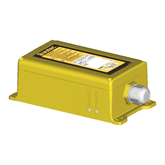
- Page 2 Identification plate Cable gland Electronic module and address DIP switches Internal light signals STOP outputs SAFETY outputs STOP contacts protection fuses SAFETY contacts protection fuses Connector for power supply unit Power supply protection fuse Command outputs LIRLBE00-03 AUTEC - Air series...
- Page 3 A technical data sheet must always be kept toghether with this manual (always keep a copy of the technical data sheet when it is used for administrative purposes). The wiring of the receiving unit outputs must always reflect the wiring indicated in the technical data sheet. AUTEC - Air series LIRLBE00-03...
- Page 4 (S/N), bar code and manufacturing year. MODEL, TYPE and main receiving unit On the cover of the technical data plate technical data, marking and possible receiving unit. radio remote control marks. LIRLBE00-03 AUTEC - Air series...
- Page 5 The ENABLE LED indicates the status of the radio link. The enABLe LeD … Meaning … blinks once every 5 seconds The receiving and transmitting unit do not communicate. The unit is ready to receive commands sent by the … blinks fast transmitting unit. AUTEC - Air series LIRLBE00-03...
- Page 6 The activation of each relay on the mother board is signalled by an LED near the relay. Command outputs The data sheet contains information regarding the correspondence between the commands sent by the transmitting unit and the related output enabled in the receiving unit. LIRLBE00-03 AUTEC - Air series...
- Page 7 Check the protection fuses of the STOP LeD blinks fast. the commands sent. contacts or of the SAFETY contacts and, if needed, replace them. AUTEC - Air series LIRLBE00-03...
Need help?
Do you have a question about the Air ACRS13-L and is the answer not in the manual?
Questions and answers