AUTEC AIR Series Instruction Manual
Radio remote control
Hide thumbs
Also See for AIR Series:
- Instruction manual (52 pages) ,
- Instruction manual for the use and the maintenance (44 pages) ,
- Original instructions manual (28 pages)
Table of Contents
Advertisement
Original instructions
Instruction Manual for the use and the
maintenance of the Radio Remote Control
AIR SERIES
Part C: SIDEKICK SK4 Transmitting Unit
AUTEC SRL
Via Pomaroli, 65
36030 Caldogno (VI), ITALY
Phone: +39 0444 901000
Fax: +39 0444 901011
Email: info@autecsafety.com
www.autecsafety.com
LIUSK4N00_eng-00
Advertisement
Table of Contents

Subscribe to Our Youtube Channel
Related Manuals for AUTEC AIR Series


Summary of Contents for AUTEC AIR Series
- Page 1 Original instructions Instruction Manual for the use and the maintenance of the Radio Remote Control AIR SERIES Part C: SIDEKICK SK4 Transmitting Unit AUTEC SRL Via Pomaroli, 65 36030 Caldogno (VI), ITALY Phone: +39 0444 901000 Fax: +39 0444 901011 Email: info@autecsafety.com...
- Page 3 Autec Radio Remote Control and all of its components are done solely and completely in accordance with this Manual, and with all local applicable laws, safety rules and standards (all of the foregoing referred to herein as “Laws, Regulations and...
- Page 4 Autec instructions and warnings and all applicable Laws, Regulations and Standards, even local. Autec is not responsible for and shall not be held liable for any alteration or modification of the Autec Radio Remote Control, or the use of non-Autec components or products used with or incorporated into the Autec Radio Remote Control.
- Page 5 IT IS THE RESPONSIBILITY OF THE OWNER AND FACILITY OPERATOR, AND THEIR OFFICERS, MANAGERS AND SUPERVISORS, to be certain that the areas in which the Machine operated by or through the Autec Radio Remote Control is located and operate are clearly delineated and marked in accordance with all Autec warnings and...
-
Page 6: Table Of Contents
8.13 BACK-UP UNIT ................... 27 Instructions for the User ..................28 Usage restrictions ..................28 User behaviour .................... 28 Belt or harness .................... 29 Maintenance ......................32 Malfunction signalled by the Transmitting Unit ..........32 Decommissioning and disposal ................. 34 LIUSK4N00_eng-00 AUTEC... -
Page 7: Information On The Use Of Instructions
(Part A) of the Manual provided with the Radio Remote Control. Structure of the Instruction Manual The Manual for the use and maintenance of Autec Air series Radio Remote Controls consists of different parts, that form the Manual altogether; the Manual must be read carefully, understood and applied by the Radio Remote Control's Owner, User and by all those Persons that, for any reasons, may operate with the Radio Remote Control or with the Machine where it is installed. - Page 8 Receiving Unit. Usage and maintenance instruction as a whole are to be considered as an integral part both of the Autec Radio Remote Control and of the Machine, system, device or Machinery system where the Radio Remote Control is installed.
-
Page 9: Caption And Terminology
Information on the use of instructions Caption and terminology Contact Autec if any of the instructions, symbols, warnings or images are not clear and understandable, or if you have doubts or questions. In this part of the Manual, the terms listed below have the same meaning explained in the... -
Page 10: To Whom The Instructions Are Addressed
Regulation for the storage of instructions are described in the paragraph with the same title in the general part: please refer to that part. Intellectual property Restrictions connected to intellectual property are described in the paragraph with the same title in the general part: please refer to that part. LIUSK4N00_eng-00 AUTEC - Air series... -
Page 11: Brief Product Presentation
Brief product presentation Series, Radio Remote Control and Unit The object of this part of the Manual is the SK4 Transmitting Unit of a Air series' Radio Remote Control. Autec Air series' Radio Remote Controls are designed to be used on Machines and provide a command interface to their command and control system, to be used from an appropriate distance and position. -
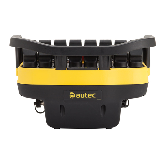
Page 12: Description Of The Transmitting Unit
CHARGE LED Actuators (selectors or pushbuttons) START actuator Connector for the Unit's recharge STOP pushbutton Technical data plate Transmitting Unit identification plate Radio Remote Control identification plate DIP switches Connector for "ID internal tx memory" LIUSK4N00_eng-00 AUTEC - Air series... -
Page 13: Technical Data
A Technical Data Sheet must always be kept together with this Manual: if you need to use the Technical Data Sheet for administrative purposes (tests, check, etc.), make a copy of it. The wiring of the Receiving Unit's outputs must always reflect the wiring indicated in the Technical Data Sheet. AUTEC - Air series LIUSK4N00_eng-00... -
Page 14: Plates
Transmitting Unit identification number identification plate Transmitting Unit (TU ID) MODEL, TYPE and main Transmitting Back side of the Technical data plate Unit technical data, marking and Transmitting Unit possible Radio Remote Control marks LIUSK4N00_eng-00 AUTEC - Air series... -
Page 15: Plates On The Sk4 Transmitting Unit In A "Multi Units" Or "Multi Receiver" Radio Remote Control
Transmitting Unit identification number identification plate Transmitting Unit (TU ID) MODEL, TYPE and main Transmitting Back side of the Technical data plate Unit technical data, marking and Transmitting Unit possible Radio Remote Control marks AUTEC - Air series LIUSK4N00_eng-00... -
Page 16: Light Signals
The meaning of red LED [A] and green LED [B] lighting is described in the following tables; possible actions to carry out are given in chapter 11. The meaning of the red and green LED signals cannot be modified. LIUSK4N00_eng-00 AUTEC - Air series... - Page 17 The red LED [A] blinks slowly (one The battery has less than 2h run time. blink per second). The red LED [A] blinks fast. The battery has a 10min run time. AUTEC - Air series LIUSK4N00_eng-00...
-
Page 18: Green Charge Led [D] And Red Charge Led [E]
The green CHARGE LED [D] is The Transmitting Unit is under charge and charging has steady on. been completed. The red CHARGE LED [E] is steady The Transmitting Unit is under charge and charging has not been completed yet. LIUSK4N00_eng-00 AUTEC - Air series... -
Page 19: General Operating Instructions
The SK4 Transmitting Unit contains a rechargeable battery (AIRBM3V7L); the provided battery is already partially charged. To recharge the SK4 Unit you must only use the cable supplied by Autec: connect it to a power supply source providing the values given in the technical data that are indicated in "Part E"... -
Page 20: Id Internal Tx Memory
This key is inside the Transmitting Unit. The Technical Data Sheet indicates if the "ID internal tx memory" is present (DIP switch 2 is set in the ON position). ID internal tx memory S/N: XXXXXXX LIUSK4N00_eng-00 AUTEC - Air series... -
Page 21: Starting Up The Radio Remote Control
Note: default PIN code set by AUTEC is: - PIN 1=START. - PIN 2=S0 (see Technical Data Sheet). - PIN 3=START. Autec will set a customized PIN code only upon request by the Machine Manufacturer or the Installer. AUTEC - Air series LIUSK4N00_eng-00... -
Page 22: Command Activation
- No movement: the function activates when the Transmitting Unit remains static (acceleration lower than 0.5g) for more than 4 minutes. - Tilt the G-Sense function activates when the Transmitting Unit is tilted by at least 50° for at least 4 minutes. LIUSK4N00_eng-00 AUTEC - Air series... - Page 23 General operating instructions Autec sets the G-Sense function so that when the sensor activates, one of the following situations occurs: - the Transmitting Unit switches off, - all the Radio Remote Control's commands are deactivated, except one particular Machine function, which is activated at the same time (e.g. horn).
-
Page 24: Using The Transmitting Unit While Recharging
The SK4 Unit may or may not be enabled to control the Machine while the Unit itself is being charged. This activation depends on the "Charger Plug Enable" setting. Autec sets this function only upon request by the Installer and under his own responsibility. -
Page 25: Radio Link Interruption
(SWITCH-OFF) to zero. Setting or removal of the automatic switch off time (SWITCH-OFF) is done by Autec and decided by the Machine Manufacturer or by the Installer, depending on the efficiency and functions they need on the Machine. -
Page 26: Switching Off The Transmitting Unit
If the green LED repeats the sequence "three blinks and a pause", there is no information and/or signals coming from the "Data Feedback" function. In this case, bring the Transmitting Unit closer to the Receiving Unit until the green LED blinks slowly. LIUSK4N00_eng-00 AUTEC - Air series... -
Page 27: Back-Up Unit
If the Transmitting Unit cannot be used, it can be replaced with a Transmitting Unit called "BACK-UP UNIT"; you need to ask for it to Autec. It is identical to the Unit that cannot be used any more; the only difference is the presence of the plate “BACK-UP UNIT”... -
Page 28: Instructions For The User
Autec Radio Remote Controls. However, instructions given in the following paragraphs do not replace nor complete the instructions that must be provided by the Manufacturer of the Machine where an Autec Radio Remote Control (to which the SK4 Transmitting Unit belongs) is installed. -
Page 29: Belt Or Harness
- keep at a safe distance from any risk situations originating from the use of the Machine where the Autec Radio Remote Control is installed; - avoid doing anything else while using the Radio Remote Control, such as, by way of example, operate other Machines and/or other devices, eat and/or drink, use communication devices (phone, radio phone, etc.), keyboards, computers, IT devices or AV equipment,... - Page 30 Instructions for the User LIUSK4N00_eng-00 AUTEC - Air series...
- Page 31 Transmitting Unit, to the User, to people and/or property. Replace the belt or harness if it is damaged or worn. AUTEC - Air series LIUSK4N00_eng-00...
-
Page 32: Maintenance
Receiving Unit " in "Part D" of the not work correctly. (one blink per second). Manual. The red LED is steady The STOP pushbutton is Unlock the STOP pushbutton or contact on during start up pressed or damaged. the support service. LIUSK4N00_eng-00 AUTEC - Air series... - Page 33 3 blinks and given in the and a pause, and the Perform the ALIGNMENT procedure. document "Menu of red LED is steady on Transmitting Unit (MTU)" during start up. has been carried out. AUTEC - Air series LIUSK4N00_eng-00...
-
Page 34: Decommissioning And Disposal
Decommissioning and disposal Instructions for correct decommissioning and disposal of Radio Remote Controls are described in chapter "Decommissioning and disposal" in "Part A" of the Instruction Manual. Therefore, please refer to that part of the Manual. LIUSK4N00_eng-00 AUTEC - Air series...
Need help?
Do you have a question about the AIR Series and is the answer not in the manual?
Questions and answers