Table of Contents
Advertisement
Advertisement
Table of Contents

Related Manuals for TOORX TRX 50 S EVO


Summary of Contents for TOORX TRX 50 S EVO
- Page 1 INSTRUCTION...
-
Page 2: Carton Contents
Carton Contents Main Frame Left Mast Cover Right Mast Cover Hardware pack 66# M8¡ Á 8 0mm Allen Bolt (Qty2) 68# M8¡ Á 2 0mm Allen Bolt (Qty4) ST4.8 ¡ Á 1 5mm Philip Screw w/washer(Qty2) 54# M8¡ Á 9 0mm Allen Bolt (Qty4) Multi Wrench (Qty1) 57# M8¡... -
Page 3: Hardware Pack Contents
Hardware Pack Contents 8mm Washer × 14 80mm Allen Bolt × 2 20mm Allen Bolt × 4 8mm Spring Washer × 14 15mm Phillips Screw × 2 90mm Allen Bolt × 4 15mm Allen Bolt × 4 5# Allen Wrench × 1 6# Allen Wrench ×... -
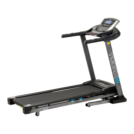
Page 4: Product Overview
Product Overview Pulse Sensor Handle Grip Safety Key Console Mast Motor Cover Side Rail Running Deck Console Mast Cover Transport Wheel End Cap... -
Page 5: Assembly Instructions
Assembly Instructions Step 1 1.1 Thread the Main Wire from the bottom of the Right Console Mast (4) to the top and through the opening. 1.2 Attach Left Console Mast (3) and Right Console Mast (4) to the Base Frame (1) using 4 x M8 x 15mm Allen Bolts (57), 2 x M8 x 80mm Allen Bolts (66), 4 x M8 x 90mm Allen Bolts (54), 10 x 8mm Spring Washers (87) and 10x 8mm Washers (84). - Page 6 Step 2 2.1 Take the console and connect the wires from the Left Console Mast (3) and Right Console Mast (4) to the wires from the console, there will be two wires from the Left Console Mast (3) and three from the Right Console Mast (4).
- Page 7 Step 3 3.1 Attach the Left Mast Cover (20) and Right Mast Cover (21) by inserting the fastener located on the end of the mast covers into the groove on the Base Frame (1). 3.2 Secure the Left Mast Cover (20) and Right Mast Cover (21) in place using 2 x ST4.8 x 15mm Dome Head Philips Screws (71) to attach them to the Left Console Mast (3) and Right Console Mast (4).
- Page 8 Starting the Treadmill To start the treadmill simply plug in the power cord and turn on the switch. You will hear a signal tone and the screen of the console will light up. There is an over-current protector located on the right side of the switch (see above picture); in case of short circuit or over-current, the button of the over current protector will pop up and the treadmill will power off.
- Page 9 Console Overview A Quick Incline Select B Quick Speed Select C Start D Stop E Incline- F Speed+ G Incline+ H Speed- I MODE J Prog K Distance or cal L Pulse or incline M Time N Speed O prog Q Incline+ R Incline - S Speed +...
-
Page 10: Console Displays
Console Displays TECHNICAL SPECIFICATION Time = 0:00-99:59 min Speed = 1.0-18.0 km/h Distance = 0.00-99.9 km Calorie = 0-999 cal Incline = 0-15% Pulse = 50-200 beats/min START Press to start exercise with initial speed 1.0km/h STOP Press during workout and the treadmill will stop by gradually reducing the speed and incline. QUICK SPEED SELECT Press to select your desired running speed with 4, 8, 12, 16km/h QUICK INCLINE SELECT... -
Page 11: General Operation
General Operation Turn on the power switch at the front of your Treadmill. This switch is located next to the mains power cord inlet. Place the safety key into the magnetic grove in the middle of the console. The console will give an audible signal and all console window displays will display a value of 0. - Page 12 Turn on the treadmill and press the “Mode” button three times, the “Cal” window will flash and display “50”, which is the pre-set burning calories of the treadmill. Press “Speed +” / “Speed -” or press “Incline +”/ “Incline -”buttons to select target burning calories, the range is 10 to 999 cal. Once you have set the desired workout calorie burning, press the “Start”...
- Page 14 PULSE WORKOUT MODE Turn on the treadmill and press the “PROG” button until the “Prog.” window displays “HP1”. The “Time” window will display “30:00”, which is the pre-set workout time for the pulse workout mode. Press the “Speed +” / “Speed -” or “Incline +” / “Incline -” buttons to select your desired training time. Press the “MODE”...
- Page 15 User’s Target Heart Rate Table Heart Beat Heart Beat Heart Beat (Times/Mins) (Times/Mins) (Times/Mins) Default Default Default...
- Page 16 BODY FAT ANALYSIS Turn on the treadmill and press the “PROG” button until the “Prog.” window displays “FAT”. Press the “MODE” button and the “Incline” window will display “F-1” and the “Dis.” window will display “01”. Press the “Speed +” / “Speed -” or “Incline +” / “Incline -” buttons to select your sexual distinction, “01” being male and “02”...
- Page 17 Maintenance Proper maintenance is very important to ensure a faultless and operational condition of the treadmill. Improper maintenance can cause damage to the treadmill or shorten the life of the product and exceed the LIMITED WARRANTY coverage. Important: Never use abrasives or solvents to clean the treadmill. To prevent damage to the computer, keep liquids away and keep it out of direct sunlight.
- Page 18 ADJUSTING THE MOTOR BELT During your workout, if you find the running belt is not running smoothly then it means that the motor belt is loosened. To solve the issue please follow the below steps to adjust the tension. Turn the motor belt adjustment bolt clockwise ¼ turn using the 6 Allen Key (104). Re-start the treadmill and run on the treadmill.
-
Page 19: Exploded Diagram
Exploded Diagram... -
Page 20: Parts List
Parts List Note: Some of the below parts are pre-assembled to the master component and may not be supplied separately. Key No. Description Key No. Description Base frame End Cap Running stage M8 Aircraft nut Left console mast φ40×φ10×2mm Washer Right console mast Flinger Console frame... - Page 21 End Cap M8×90mm Allen bolt Key No. Description Key No. Description PC Board M4×10mm Philips Screw Steel bracket M10 Aircraft Nut M8×15mm Allen bolt M8 Aircraft Nut Ф23×Ф9×3.0 rubber M3 Hex Nut bumper Ф10mm Washer Sticker Air spring Ф8mm Washer φ25×φ15×5mm Washer Ф3mm Washer M8×24mm Philips Screw...
- Page 22 GARLANDO SPA Via Regione Piemonte, 32 - Zona Industriale D1 15068 - Pozzolo Formigaro (AL) - Italy www.toorx.it - info@toorx.it...
Need help?
Do you have a question about the TRX 50 S EVO and is the answer not in the manual?
Questions and answers