Sign In
Upload
Download
Table of Contents
Contents
Add to my manuals
Delete from my manuals
Share
URL of this page:
HTML Link:
Bookmark this page
Add
Manual will be automatically added to "My Manuals"
Print this page
×
Bookmark added
×
Added to my manuals
Manuals
Brands
Amada Manuals
Saw
HFA-250
Operator's manual
Amada HFA-250 Operator's Manual
Horizontal bandsaw
Hide thumbs
1
2
Table Of Contents
3
4
5
6
7
8
9
10
11
12
13
14
15
16
17
18
19
20
21
22
23
24
25
26
27
28
29
30
31
32
33
34
35
36
37
38
39
40
41
42
43
44
45
46
47
48
49
50
51
52
53
54
55
56
57
58
59
60
61
62
63
64
65
66
67
68
69
70
71
72
73
74
75
76
77
78
79
80
81
82
83
84
85
86
87
88
89
90
91
92
93
94
95
96
97
98
99
100
101
102
103
104
105
106
107
108
109
110
111
112
113
114
115
116
117
118
119
120
121
122
123
124
125
126
127
128
129
130
131
132
133
134
135
136
137
138
139
140
141
142
143
144
145
146
147
148
149
150
151
152
153
154
155
156
157
158
159
160
161
162
163
164
165
166
167
168
169
170
171
172
173
174
page
of
174
Go
/
174
Contents
Table of Contents
Troubleshooting
Bookmarks
Table of Contents
Table of Contents
Safety Rules & Cutting Precautions
Description
Identification of Machine Parts
HFA-250 and HFA-250W Machines
HFA-400 and HFA-400W Machines
Specifications
HFA-250 and HFA-250W Machines
HFA-400 and HFA-400W Machines
Sound Level
Automatic Backgauge Function
Optional Accessories
Installation
Location
Carrying
Cleaning
Leveling
Removing Shipping Bracket
Supplying Hydraulic Oil
Supplying Cutting Fluid
Supplying Electric Power
Connecting Power Cable
Checking Electrical Connections
Installing Fire Control Devices
Controls
Machine Circuit Breaker Switch
Control Panel
Other Controls
Description of Displays
Contents of Displays
Initial Display
Station Data Setup Display
All Station Delete Confirmation Display
Runout Setup Display
Station Delete Confirmation Display
Setup Display
Result Display
Daily Report Display
ALARM HISTORY Display
PASSWORD Display
Part IV Operation
Inspection before Start of Day'swork
Turning on Machine
Selecting Saw Blade
Unfolding and Folding Saw Blade
Unfolding Saw Blade
Folding Saw Blade
Installing Saw Blade
Adjusting Position of Wire Brush
Adjusting Position of Movable Saw Blade Guide
Loading and Positioning Work
Loading Work
Positioning Work
Positioning Remnant for Cutting Further
Semiautomatic Positioning Function
Setting Cutoff Length
Semiautomatic Positioning
Adjusting Cutting Fluid Flow Rate
Running in New Saw Blade
Stack Cutting
Stacking Workpieces
Using Multi-Vises (Optional
Runout Detector (Optional
Setting Runout Tolerances
Handling Cutting Data
Entering and Storing Cutting Data
Checking Cutting Data (Calling Station
Changing Cutting Data
Canceling Cutting Data
Conditions for Execution of Cutting Data
Head-End Positioning Function (Optional
Setting Cutoff Length
Head-End Positioning Operation
Going from Head-End Positioning Operation to Automatic Operation
Operation
Manual Operation
Starting Cutting
Ending Cutting
Interrupting or Stopping Cutting
Automatic Operation
Before Starting Automatic Operation
Starting Cutting Without Trimming Head End
Starting Cutting after Trimming Head End
Ending Automatic Operation
Interrupting Automatic Operation
Stopping Automatic Operation after Detection of Excessive Runout
Stopping Automatic Operation
Interrupt Station Function
Inserting Interrupt Station in Current Station
Inserting Interrupt Station between Stations to be Executed
Inserting Interrupt Station as First Station of Automatic Operation During Head-End Trimming
Self-Diagnostic Function
Ending Operation
Part V Troubleshooting
Operating Troubles
Alarm Code List
Part VI Maintenance
Checking before Start of Day'swork
Periodic Maintenance
Every Day
Cleaning
Lubrication
Every Month
Cleaning
Lubrication
First Three Months (or 500 Hours
Changing Speed Reducer Oil (for First Time
Every Six Months
Changing Cutting Fluid
Changing Hydraulic Oil
Checking and Changing Backup Rollers
Checking and Changing Guide Rollers
Every Year
Changing Speed Reducer Oil (for Second and Subsequent Times
Changing Speed Reducer Oil
(For Second and Subsequent Times
Appendix A Options
Multi-Vises
Vise Pressure Control Valves
Runout Detector (Factory Option
Roller Table
Roller Stand
Head-End Positioning Function (Factory Option
Rotating Beacon Lights (Factory Option
Wheel Cover Open Limit Switch (Factory Option
Appendix B Safety Data Sheets
Shell Tellus Oil C32
Esso Lithtan EP2
Amada Gear Oil EP320
Advertisement
Quick Links
1
Hfa-250 and Hfa-250W Machines
2
Hfa-400 and Hfa-400W Machines
3
Control Panel
4
Alarm Code List
Download this manual
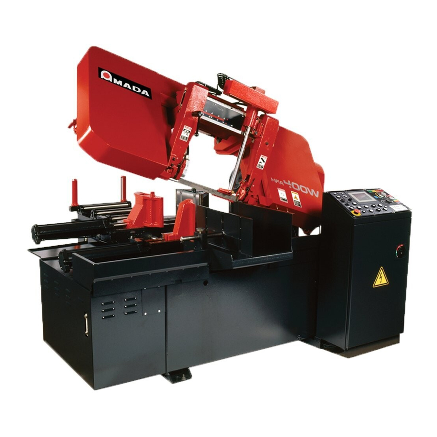
HORIZONTAL BANDSAW
HFA-250/250W/400/400W
(HFA-252T/252TW/407T/407TW)
OPERATOR'S MANUAL
E01
HFA250/400T/TW US-
-200409
Table of
Contents
Previous
Page
Next
Page
1
2
3
4
5
Advertisement
Table of Contents
Need help?
Do you have a question about the HFA-250 and is the answer not in the manual?
Ask a question
Questions and answers
Related Manuals for Amada HFA-250
Saw Amada HFA-400W Operator's Manual
Horizontal bandsaw (174 pages)
Saw Amada HFA-400 Operator's Manual
Horizontal bandsaw (174 pages)
Saw Amada vm Series Operator's Manual
Bandsawing machine (140 pages)
This manual is also suitable for:
Hfa-400w
Hfa-250w
Hfa-400
Hfa-252tw
Hfa-407t
Hfa-407tw
...
Show all
Hfa-252t
Table of Contents
Save PDF
Print
Rename the bookmark
Delete bookmark?
Delete from my manuals?
Login
Sign In
OR
Sign in with Facebook
Sign in with Google
Upload manual
Upload from disk
Upload from URL


Need help?
Do you have a question about the HFA-250 and is the answer not in the manual?
Questions and answers