Emerson Micro Motion Elite Coriolis Micro Motion Elite Coriolis CMF025 Installation Manual
Flow and density sensors
Hide thumbs
Also See for Micro Motion Elite Coriolis Micro Motion Elite Coriolis CMF025:
- Installation manual (42 pages)

Related Manuals for Emerson Micro Motion Elite Coriolis Micro Motion Elite Coriolis CMF025


Summary of Contents for Emerson Micro Motion Elite Coriolis Micro Motion Elite Coriolis CMF025
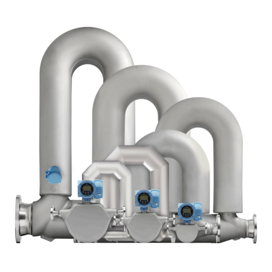
- Page 1 Installation Manual 20002158, Rev DM January 2018 ® ® Micro Motion ELITE Coriolis Flow and Density Sensors...
- Page 2 Micro Motion employees. Micro Motion will not accept your returned equipment if you fail to follow Micro Motion procedures. Return procedures and forms are available on our web support site at www.emerson.com, or by phoning the Micro Motion Customer Service department.
-
Page 3: Table Of Contents
Contents Contents Chapter 1 Planning ...........................1 Installation checklist ........................1 Best practices ..........................3 Temperature limits .........................3 Recommendations for hygienic and self-draining applications ............6 Chapter 2 Mounting .........................8 Recommendations for lifting heavy meters ..................8 Mount the sensor ......................... 10 Rotate junction box or 800 core processor (optional) .............. - Page 4 Contents Micro Motion ELITE...
-
Page 5: Chapter 1 Planning
Planning Planning Topics covered in this chapter: • Installation checklist • Best practices • Temperature limits • Recommendations for hygienic and self-draining applications Installation checklist □ Make sure that the hazardous area specified on the approval tag is suitable for the environment in which the meter will be installed. - Page 6 Planning Table 1-3: Preferred sensor orientation Preferred orienta- Process Alternate orientations tion Liquids Gases Slurries □ Install the meter so that the flow direction arrow on the sensor case matches the actual forward flow of the process. (Flow direction is also software-selectable.) Micro Motion ELITE...
-
Page 7: Best Practices
• Temperature limits may be further restricted by hazardous area approvals. Refer to the hazardous area approvals documentation shipped with the sensor or available at www.emerson.com. • The extended-mount electronics option allows the sensor case to be insulated without covering the transmitter, core processor, or junction box, but does not affect temperature ratings. - Page 8 Planning Ambient and process temperature limits for ELITE CMFS007, CMFS025–CMFS150 meters 140 (60) 140 (60) (45) –40 (–40) –148 (–100) –58 (–50) 400 (204) proc = Ambient temperature °F (°C) = Process temperature °F (°C) proc A = All available electronic options B= Remote mount electronics only Ambient and process temperature limits for ELITE CMF***M/L/H/P (excludes special order cryogenic modifications) and CMFS010-015 meters...
- Page 9 Planning Ambient and process temperature limits for special order cryogenic ELITE meters 140 (60) –40 (–40) –148 (–100) –400 (–240) (80) proc = Ambient temperature °F (°C) = Process temperature °F (°C) proc A = All available electronic options B= Remote mount electronics only Ambient and process temperature limits for high temperature ELITE meters 140 (60) –40 (–40)
-
Page 10: Recommendations For Hygienic And Self-Draining Applications
Planning Ambient and process temperature limits for Super Duplex ELITE meters 140 (60) 140 (60) (45) –40 (–40) –148 (–100) –40 (–40) 400 (204) proc = Ambient temperature °F (°C) = Process temperature °F (°C) proc A = All available electronic options B= Remote mount electronics only Note For Super Duplex models operating above 177 °C, please consult the factory before purchase. - Page 11 Planning Figure 1-1: Installation for self-draining applications Process pipeline Direction of normal process flow Direction of drainage Installation Manual...
-
Page 12: Chapter 2 Mounting
Mounting Mounting Topics covered in this chapter: • Recommendations for lifting heavy meters • Mount the sensor • Rotate junction box or 800 core processor (optional) • Mount electronics of high-temperature sensors • Mount a CMF010 sensor to a wall or pole Mount a CMFS007, CMFS010 or CMFS015 sensor in a bracket •... - Page 13 Figure 2-2: Center of gravity for large meters Typical center of gravity Note Complete and detailed dimensional drawings, including the location of the center of gravity, can be found through the product drawings link in our online store (www.emerson.com). Installation Manual...
-
Page 14: Mount The Sensor
Mounting Mount the sensor Use your common practices to minimize torque and bending load on process connections. To reduce the risk of condensation problems, do not orient transmitters or sensor junction boxes with their conduit openings pointing upward. CAUTION! Do not lift the sensor by the electronics or purge connections. Lifting the sensor by the electronics or purge connections can damage the device. -
Page 15: Rotate Junction Box Or 800 Core Processor (Optional)
Mounting Rotate junction box or 800 core processor (optional) An integrally mounted junction box or 800 core processor can be rotated to one of eight possible positions in 45 degree increments. Figure 2-4: Parts for rotating the junction box or 800 core processor on the sensor Housing Clamping ring Clamping ring screw... -
Page 16: Mount Electronics Of High-Temperature Sensors
Mounting Mount electronics of high-temperature sensors The electronics of high-temperature sensors are attached to the end of a 32" (812 mm) pre-installed flexible conduit. The electronics must be separately mounted on a wall or instrument pole. Figure 2-5: Components of a high-temperature sensor Sensor Electronics Mounting bracket... - Page 17 Mounting Figure 2-6: Removing electronics from the sensor case Detach electronics from sensor case and mount to a wall or instrument pole Procedure • For wall mounting, use four 5/16" or four M8 bolts to secure the mounting bracket. Installation Manual...
- Page 18 Mounting Figure 2-7: Wall-mount components A. Wall or flat surface B. Electronics (enhanced core processor shown) C. Flexible conduit • For mounting to an instrument pole, use a 2-inch U-bolt pipe kit to secure the mounting bracket. Micro Motion ELITE...
- Page 19 Mounting Figure 2-8: Pole-mount components A. Instrument pole B. Electronics (enhanced core processor shown) C. Flexible conduit Installation Manual...
-
Page 20: Mount A Cmf010 Sensor To A Wall Or Pole
Mounting Mount a CMF010 sensor to a wall or pole The CMF010 sensor has an optional mounting configuration for use with small or flexible pipeline. If the pipeline adequately supports the sensor, you can skip this procedure. Locate the optional mounting holes. For sensors with a junction box, the junction box must be rotated to the side to expose the mounting holes. -
Page 21: Mount A Cmfs007, Cmfs010 Or Cmfs015 Sensor In A Bracket
Mounting Mount a CMFS007, CMFS010 or CMFS015 sensor in a bracket The CMFS007, CMFS010 and CMFS015 sensors have an optional mounting bracket for use with small or flexible pipeline. If the pipeline adequately supports the sensor, this procedure can be skipped. Secure the mounting bracket to a wall or other flat surface with four user-supplied 5/16"... -
Page 22: Mount A Cmfs025, Cmfs040 Or Cmfs050 Sensor In A Wall Mount Bracket
Mounting Mount a CMFS025, CMFS040 or CMFS050 sensor in a wall mount bracket The CMFS025, CMFS040, and CMFS050 sensors have an optional wall mounting bracket. Assemble the bracket. Figure 2-11: Assembled wall mounting bracket for CMFS025, CMFS040, and CMFS050 Attach the bracket to the wall using fasteners appropriate for the mounting surface. Place the sensor into the bracket. -
Page 23: Secure Wafer-Style Process Connections
Mounting Secure wafer-style process connections A wafer-style connection lets you clamp the sensor into the pipeline. A wafer installation kit is shipped with a wafer-style sensor. Make sure that the bolts provided are rated for your process connection. Slip the sensor alignment rings over each end of the sensor wafer, then insert the sensor between the process connections in the pipeline. -
Page 24: Attach Extended Electronics
Mounting Figure 2-14: Alignment ring usage A. Direction to rotate the alignment ring B. Direction the flange bolts are pushed C. Flange bolt With a wrench, tighten the nuts in an alternating order. Attach extended electronics If your installation has a sensor with extended electronics, you will need to install the extender onto the sensor case. - Page 25 Mounting Figure 2-15: Feedthrough and extender components A. Transmitter or core processor B. Extender C. O-ring D. Feedthrough E. Clamping ring F. Clamping screw G. Plastic plug H. Plastic cap Loosen the clamping screw and remove the clamping ring. Leave the O-ring in place on the feedthrough.
-
Page 26: Transmitter Power And I/O Wiring
Transmitter power and I/O wiring Transmitter power and I/O wiring Topics covered in this chapter: • Options for wiring • Connect 4-wire cable • Connect the 9-wire cable Options for wiring The wiring procedure you follow depends on which electronics option you have. Table 3-1: Wiring procedures by electronics option Electronics option... -
Page 27: Connect 4-Wire Cable
Transmitter power and I/O wiring CAUTION! Fully close and tighten all housing covers and conduit openings. Improperly sealed housings can expose electronics to moisture, which can cause measurement error or flowmeter failure. Inspect and grease all gaskets and O-rings. Connect 4-wire cable 3.2.1 4-wire cable types and usage Micro Motion offers two types of 4-wire cable: shielded and armored. - Page 28 Transmitter power and I/O wiring 3.2.3 Prepare a cable with user-supplied cable glands Remove the core processor cover using a flat-blade screw driver. Pass the wires through the gland nut and gland body. A. Gland body B. Gland nut Terminate the RS-485 shield and drain wires to the housing internal grounding screw.
- Page 29 Transmitter power and I/O wiring A. Drain wires wrapped around shield For foil (shielded cable) only: Note For braided (armored cable) skip this step and contine to the next step. Option Description NPT gland a. Slide the shielded heat shrink over the drain wires. Ensure that the wires are type completely covered.
- Page 30 Transmitter power and I/O wiring A. Shield folded back B. Gland body 3.2.5 Connect the wires to the core processor terminals After the 4-wire cable has been prepared and shielded (if required), connect the individual wires of the 4-wire cable to the terminals on the core processor. Connect the wires to the core processor terminals.
-
Page 31: Connect The 9-Wire Cable
Transmitter power and I/O wiring A. Terminal 1 (Power supply +): Red wire B. Terminal 2 (Power supply -): Black wire C. Terminal 3 (RS-485/A): White wire D. Terminal 4 (RS-485/B): Green wire Reinstall the core processor cover. Torque the cover screws to: •... -
Page 32: Chapter 4 Grounding
Grounding Grounding The meter must be grounded according to the standards that are applicable at the site. The customer is responsible for knowing and complying with all applicable standards. Prerequisites Micro Motion suggests the following guides for grounding practices: • In Europe, IEC 79-14 is applicable to most installations, in particular Sections 12.2.2.3 and 12.2.2.4. -
Page 33: Chapter 5 Supplementary Information
Supplementary information Supplementary information Topics covered in this chapter: • Purge the sensor case • Pressure relief Purge the sensor case If the sensor has purge fittings, they should remain sealed at all times. The sensor is purged of all oxygen and sealed at the factory. If the purge plugs are never removed, it is not necessary to purge or re-seal the sensor. - Page 34 Supplementary information Prepare the purge plugs for reinstallation by wrapping them with 2–3 turns of Teflon tape. Connect the supply of nitrogen or argon gas to the inlet purge connection or open inlet purge line. Leave the outlet connection open. •...
- Page 35 Supplementary information Table 5-1: Purge time (continued) Sensor model Purge rate, in ft /hr (l/h) Time, in minutes CMFS050 20 (566) 4 1/2 CMFS075 20 (566) CMFS100 20 (566) CMFS150 20 (566) At the appropriate time, shut off the gas supply, then immediately seal the purge outlet and inlet connections with the purge plugs.
-
Page 36: Pressure Relief
Supplementary information Pressure relief ELITE sensors are available with a rupture disk installed on the case. Rupture disks are meant to vent process fluid from the sensor case in the unlikely event of a flow tube breach. Some users connect a pipeline to the rupture disk to help contain escaping process fluid. - Page 37 Supplementary information WARNING! Removing the Purge Fitting, Blind Plug, or Rupture Disks compromises the Ex-i Safety Certification, the Ex-tc Safety Certification, and the IP-rating of the Coriolis meter. Any modification to the Purge Fitting, Blind Plug, or Rupture Disks must maintain a minimum of IP66/IP67 Ratings.
- Page 38 © 2018 Micro Motion, Inc. All rights reserved. The Emerson logo is a trademark and service mark of Emerson Electric Co. Micro Motion, ELITE, ProLink, MVD and MVD Direct Connect marks are marks of one of the Emerson Automation Solutions family of companies. All other marks are property of their respective owners.
Need help?
Do you have a question about the Micro Motion Elite Coriolis Micro Motion Elite Coriolis CMF025 and is the answer not in the manual?
Questions and answers