Table of Contents
Advertisement
Instruction Manual
D200100X012
Fisherr 249 Cageless Displacer Sensors
Contents
. . . . . . . . . . . . . . . . . . . . . . . . . . . . . . . . .
. . . . . . . . . . . . . . . . . . . . . . . . . . . . .
. . . . . . . . . . . . . . . . . . . . . . . . . . . . . . . . .
. . . . . . . . . . . . . . . . . . . . . . . . .
. . . . . . . . . . . . . . . . . . . . . . . . . . . . . . . . .
. . . . . . . . . . . . . . . . . . . . . . . . . . . .
. . . . . . . . . . . . . . . . . . . . . . . . . . . . . . .
. . . . . . . . . . . . . . . . . . . . . . . . . . . . . . . . . . .
. . . . . . . . . . . . . . . . . . . . . . . . . . . . . . . . . . .
Introduction
Scope of Manual
This instruction manual includes maintenance and parts ordering information for Fisher 249 cageless displacer
sensors.
Although a 249 sensor is usually shipped with attached controller or transmitter, this manual does not include
operation, installation, calibration, maintenance, and parts ordering information for the controller/transmitter or for
the complete unit. For this information, refer to the appropriate controller/ transmitter instruction manual.
Do not install, operate, or maintain a 249 sensor without being fully trained and qualified in valve, actuator, and
accessory installation, operation, and maintenance. To avoid personal injury or property damage, it is important
to carefully read, understand, and follow all of the contents of this manual, including all safety cautions and
warnings. If you have any questions about these instructions, contact your
Description
249 sensors are designed to measure liquid level, interface level, or density/specific gravity inside a process vessel.
www.Fisher.com
. . . . . . . . . . . . . . . . . . . . .
. . . . . . . . . . . . . .
. . . . . . . . . .
. . . .
. . . . . . . . . . . . . . . . . . . .
. . . . . . . . . . . . . . . . . . . .
. . . . . . . . . . . . . . . . . . . . . . .
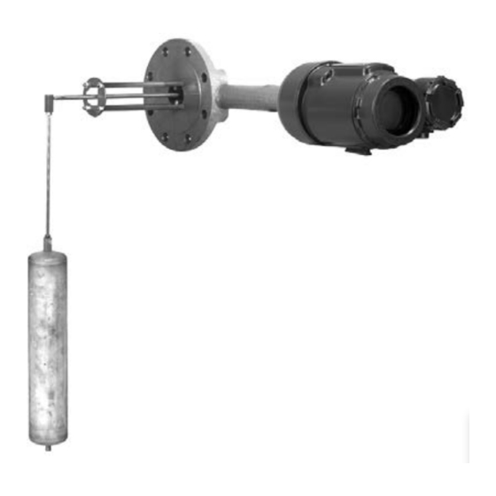
Figure 1. Fisher 249V Sensor with FIELDVUE™
DLC3010/DLC3020f Digital Level Controller
1
1
1
2
3
3
4
6
7
8
9
10
10
11
11
11
Emerson Process Management sales
249 Cageless Sensors
July 2015
office.
Advertisement
Table of Contents

Related Manuals for Emerson Fisher 249


Summary of Contents for Emerson Fisher 249
-
Page 1: Table Of Contents
W3120‐3 Introduction Scope of Manual This instruction manual includes maintenance and parts ordering information for Fisher 249 cageless displacer sensors. Although a 249 sensor is usually shipped with attached controller or transmitter, this manual does not include operation, installation, calibration, maintenance, and parts ordering information for the controller/transmitter or for the complete unit. -
Page 2: Type Number Description
Instruction Manual 249 Cageless Sensors July 2015 D200100X012 A torque tube assembly (figure 2) and displacer provide an indication of liquid level, interface level, or density/specific gravity. The torque tube assembly consists of a hollow torque tube with a shaft welded inside it at one end and protruding from it at the other end. -
Page 3: Educational Services
Torque Tube N05500 316 Stainless Steel, N06600, N10276 1. N05500 is not recommended for spring applications above 232_C (450_F). Contact your Emerson Process Management sales office or application engineer if temperatures exceeding this limit are required. Educational Services For information on available courses for 249 displacer sensors, as well as a variety of other products, contact:... -
Page 4: Removing The Displacer And Stem
Instruction Manual 249 Cageless Sensors July 2015 D200100X012 WARNING Always wear protective clothing, gloves, and eyewear when performing any maintenance operations to avoid personal injury. Avoid personal injury or property damage resulting from the sudden release of pressure. Before performing any maintenance procedure: D Relieve any process pressure in the process vessel where the 249 sensor is installed. - Page 5 Instruction Manual 249 Cageless Sensors D200100X012 July 2015 Process residue buildup on the displacer and stem (key 24) may change displacer weight or displacement. A bent stem or a dented or corroded displacer can impair performance. If the displacer rests against the travel stop, appears to be overweight, or causes output drift or other output inaccuracies, it may have been penetrated by process pressure or liquid.
-
Page 6: Replacing The Displacer, Cotter Spring, Stem End Piece, And Displacer Spud
Instruction Manual 249 Cageless Sensors July 2015 D200100X012 Be careful not to let the displacer slip and drop into the bottom of the process vessel, as displacer damage could result. 3. Carefully remove the sensor head or torque tube arm. 4. -
Page 7: Replacing The Displacer Rod/Driver Assembly
Instruction Manual 249 Cageless Sensors D200100X012 July 2015 1. After following the proper procedure to remove the sensor head and the displacer from the process vessel, move the sensor assembly to a suitable maintenance area. Support the assembly to avoid damage to the displacer, displacer stem, displacer rod/driver assembly, and associated parts. -
Page 8: Replacing The Torque Tube
Instruction Manual 249 Cageless Sensors July 2015 D200100X012 Figure 4. Torque Tube and Displacer Rod Assemblies DISPLACER ROD ASSEMBLY ROTARY SHAFT GASKET TORQUE TUBE OUTER TUBE END POSITIONING PLATE DRIVER BEARING W0145‐2 EXPLODED VIEW OF TORQUE TUBE AND DISPLACER ROD ASSEMBLY W0654‐1 REMOVAL OR INSTALLATION OF POSITIONING PLATE 6. -
Page 9: Replacing The Torque Tube Arm And Changing The Mounting
Instruction Manual 249 Cageless Sensors D200100X012 July 2015 2. Remove the controller/transmitter and displacer (key 10). Then, remove the hex nuts (key 20) that hold the torque tube arm (key 3) to the sensor head (key 2). Separate the torque tube arm from the sensor head. 3. -
Page 10: Simulation Of Process Conditions For Calibration Of Fisher Level Controllers And Transmitters
Use only genuine Fisher replacement parts. Components that are not supplied by Emerson Process Management should not, under any circumstances, be used in any Fisher instrument. Use of components not supplied by Emerson Process Management may void your warranty, might adversely affect the performance of the instrument, and could cause personal... -
Page 11: Parts Kits
2 Sensor Head Tube End Gasket For 249BP, 249CP, 249P For 249BP, 249CP, or 249V (If a part number is required, contact your Emerson Process thru CL600, graphite/SST Management sales office.) Not req'd for 249V For 249P 3 Torque Tube Arm CL900 &... - Page 12 1. This part is available in a wide variety of materials of construction, part dimensions, or other specifications. Listed here are standard or typical materials, dimensions, or specifications. Contact your Emerson Process Management sales office for assistance in selection of specific materials, dimensions, or specifications.
- Page 13 1. This part is available in a wide variety of materials of construction, part dimensions, or other specifications. Listed here are standard or typical materials, dimensions, or specifications. Contact your Emerson Process Management sales office for assistance in selection of specific materials, dimensions, or specifications.
- Page 14 Instruction Manual 249 Cageless Sensors July 2015 D200100X012 Figure 7. Fisher 249P Sensor Construction SECTION A‐A 20A2094‐C...
-
Page 15: D200100X012 July
Instruction Manual 249 Cageless Sensors D200100X012 July 2015 Figure 8. Fisher 249V Sensor Construction 30A7435‐C... - Page 16 Responsibility for proper selection, use, and maintenance of any product remains solely with the purchaser and end user. Fisher and FIELDVUE are marks owned by one of the companies in the Emerson Process Management business unit of Emerson Electric Co. Emerson Process Management, Emerson, and the Emerson logo are trademarks and service marks of Emerson Electric Co.
Need help?
Do you have a question about the Fisher 249 and is the answer not in the manual?
Questions and answers