
Related Manuals for Emerson MICRO MOTION T-SERIES


Summary of Contents for Emerson MICRO MOTION T-SERIES
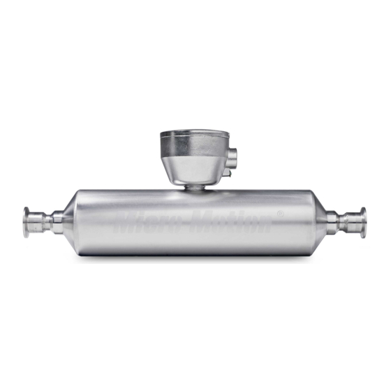
- Page 1 Installation Manual 20002172, Rev BA December 2010 ® Micro Motion T-Series Coriolis Flow and Density Sensors...
- Page 2 Safety and approval information This Micro Motion product complies with all applicable European directives when properly installed in accordance with the instructions in this manual. Refer to the EC declaration of conformity for directives that apply to this product. The EC declaration of conformity, with all applicable European directives, and the complete ATEX Installation Drawings and Instructions are available on the internet at local Micro Motion support center.
-
Page 3: Table Of Contents
Contents Chapter 1 Planning ...1 Installation checklist ...1 Best practices ...2 Environmental limits ...2 Recommendations for hygienic and self-draining applications ...3 Chapter 2 Mounting ...6 Mount the sensor ...6 Chapter 3 Wiring ...7 Options for wiring ...7 Connect 4-wire cable ...7 Connect 9-wire cable ...10 Chapter 4 Grounding ...11... - Page 4 Contents Micro Motion T-Series...
-
Page 5: Chapter 1 Planning
Planning Topics covered in this chapter: • Installation checklist • Best practices • Environmental limits • Recommendations for hygienic and self-draining applications Installation checklist □ Make sure that the hazardous area specified on the sensor approval tag is suitable for the environment in which the sensor is installed. □... -
Page 6: Best Practices
Minimize bending and torsional stress on the meter. Do not use the meter to align misaligned piping. • The sensor does not require external supports. The flanges will support the sensor in any orientation. Environmental limits Figure 1-1 for the ambient and process temperature limits of the sensor. Micro Motion T-Series... -
Page 7: Recommendations For Hygienic And Self-Draining Applications
Figure 1-1: Environmental limits for T-Series sensors 176 (80) 140 (60) 100 (38) 60 (16) 20 (7) –20 (–29) –40 (–40) –60 (–51) Notes • When ambient temperature is below –40 °F(–40 °C), a core processor or transmitter must be heated to bring its local ambient temperature to between –40 °F(–40 °C) and +140 °F(+60 °C). - Page 8 1/2-inch Tri-clamp compatible sanitary clamp DN15 DIN 11851 sanitary coupling DN15 DIN 11864-1A sanitary coupling 3/4-inch Tri-clamp compatible sanitary clamp 1-inch Tri-clamp compatible sanitary clamp 1-3. Min. angle 47° 47° 47° 47° 0° 47° 47° 0° 47° Micro Motion T-Series...
- Page 9 Table 1-3: Minimum angle of inclination Model T100F, T100T T150F, T150T Figure 1-3: Eccentric reducer Sensor case Process end connection is the same size as the sensor connection Eccentric reducer Installation Manual (continued) Fitting code Description DN25 ISO 2853 (IDF) sanitary coupling DN25 DIN 11851 sanitary coupling DN25 DIN 11864-1A sanitary coupling DN25 SMS 1145 sanitary coupling...
-
Page 10: Chapter 2 Mounting
The sensor does not require external supports. The flanges will support the sensor in any orientation. CAUTION! Do not lift the sensor by the electronics or purge connections. Lifting the sensor by the electronics or purge connections can damage the device. Figure 2-1). Micro Motion T-Series... -
Page 11: Chapter 3 Wiring
Wiring Topics covered in this chapter: • Options for wiring • Connect 4-wire cable • Connect 9-wire cable Options for wiring The wiring procedure you follow depends on which electronics option you have. Table 3-1 for the wiring options for each sensor electronics option. Table 3-1: Wiring procedures by electronics option Electronics option... - Page 12 Drain wires wrapped around shield Go to Step 2 cover Metal conduit Run conduit to User-supplied cable gland Pass the wires Lay cable in conduit through the gland Go to Step 3 Micro Motion T-Series sensor...
- Page 13 Step 2: Shield termination Braided (armored cable) Apply the Heat Shrink 1. Slide the shielded heat shrink over the drain wires. Ensure that the wires are completely covered. 2. Apply heat (250 °F or 120 °C) to shrink the tubing. Do not burn the cable.
-
Page 14: Connect 9-Wire Cable
Black wire > Terminal 2 (Power supply –) White wire > Terminal 3 (RS-485/A) Green wire > Terminal 4 (RS-485/B) Reinstall and tighten the core processor cover Connect the wires to the transmitter terminals (see the transmitter manual) Micro Motion T-Series... -
Page 15: Chapter 4 Grounding
Grounding The sensor must be grounded according to the standards that are applicable at the site. The customer is responsible for knowing and complying with all applicable standards. Prerequisites Micro Motion suggests the following guides for grounding practices: • In Europe, IEC 79-14 is applicable to most installations, in particular Sections 12.2.2.3 and 12.2.2.4. -
Page 16: Chapter 5 Supplementary Information
Connect the supply of nitrogen or argon gas to the inlet purge connection or open inlet purge line. Leave the outlet connection open. • Exercise caution to avoid introducing dirt, moisture, rust, or other contaminants into the sensor case. tape Micro Motion T-Series... - Page 17 • If the purge gas is heavier than air (such as argon), locate the inlet lower than the outlet, so that the purge gas will displace air from bottom to top. • If the purge gas is lighter than air (such as nitrogen), locate the inlet higher than the outlet, so that the purge gas will displace air from top to bottom.
- Page 18 1 Pandan Crescent Singapore 128461 Republic of Singapore T +65 6777-8211 F +65 6770-8003 Micro Motion United Kingdom Emerson Process Management Limited Horsfield Way Bredbury Industrial Estate Stockport SK6 2SU U.K. T +44 0870 240 1978 F +44 0800 966 181...
Need help?
Do you have a question about the MICRO MOTION T-SERIES and is the answer not in the manual?
Questions and answers