
Related Manuals for Emerson Micro Motion H Series


Summary of Contents for Emerson Micro Motion H Series
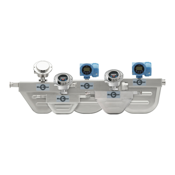
- Page 1 Installation Manual 20002346, Rev BD October 2020 ™ Micro Motion H-Series Hygienic Coriolis Flow and Density Sensors...
- Page 2 Micro Motion employees. Micro Motion will not accept your returned equipment if you fail to follow Micro Motion procedures. Return procedures and forms are available on our web support site at www.emerson.com, or by phoning the Micro Motion Customer Service department.
-
Page 3: Table Of Contents
Installation Manual Contents 20002346 October 2020 Contents Chapter 1 Before you begin......................5 1.1 About this document........................5 1.2 Hazard messages......................... 5 1.3 Related documentation....................... 6 Chapter 2 Planning........................7 2.1 Installation checklist........................7 2.2 Best practices..........................8 2.3 Temperature limits........................8 2.4 Recommendations for hygienic and self-draining applications.............9 Chapter 3 Mounting.........................11... - Page 4 Contents Installation Manual October 2020 20002346 Micro Motion H-Series...
-
Page 5: Before You Begin
Installation Manual Before you begin 20002346 October 2020 Before you begin About this document This document provides information on planning, mounting, wiring, and grounding the H- Series sensor. The information in this document assumes that users understand basic transmitter and sensor installation, configuration, and maintenance concepts and procedures. -
Page 6: Related Documentation
20002346 Related documentation You can find all product documentation on the product documentation DVD shipped with the product or at www.emerson.com. See any of the following documents for more information: • The hazardous area approvals documentation shipped with the sensor or available at www.emerson.com/flowmeasurement. -
Page 7: Chapter 2 Planning
Installation Manual Planning 20002346 October 2020 Planning Installation checklist □ Make sure that the hazardous area specified on the approval tag is suitable for the environment in which the meter will be installed. WARNING Failure to abide by approvals can cause an explosion resulting in injury or death. □... -
Page 8: Best Practices
Planning Installation Manual October 2020 20002346 Table 2-3: Preferred sensor orientation Secondary preferred Alternate suitable Process Preferred orientation orientation orientation Liquids & slurries Gases For meters installed in a horizontal orientation it is recommended to utilize forced expulsion with pressurized gas where draininability is required. □... -
Page 9: Recommendations For Hygienic And Self-Draining Applications
• Temperature limits may be further restricted by hazardous area approvals. Refer to the hazardous area approvals documentation shipped with the sensor or available from the www.emerson.com/flowmeasurement. For further questions, contact customer service. • The extended-mount electronics option allows the sensor case to be insulated without covering the transmitter, core processor, or junction box, but does not affect temperature ratings. - Page 10 Planning Installation Manual October 2020 20002346 ® • Tri-Clamp and DIN 11851 style process connections require special gaskets to comply with EHEDG requirements for hygienic design. Figure 2-1: Installation for self-draining applications A. Process pipeline B. Direction of normal process flow C.
-
Page 11: Chapter 3 Mounting
Installation Manual Mounting 20002346 October 2020 Mounting Mount the sensor NOTICE • Lifting the sensor by the electronics or purge connections can damage the device. • To reduce the risk of collecting liquid in the electronics housing, do not orient transmitters or sensor junction boxes with their conduit openings pointing upward. - Page 12 Mounting Installation Manual October 2020 20002346 NOTICE Keep the extender and feedthrough clean and dry. Moisture or debris in the extender or feedthrough can damage electronics and result in measurement error or flowmeter failure. Procedure 1. Remove and recycle the plastic cap from the feedthrough on the sensor. Figure 3-1: Feedthrough and extender components A.
-
Page 13: Transmitter Power And I/O Wiring
Installation Manual Transmitter power and I/O wiring 20002346 October 2020 Transmitter power and I/O wiring Options for wiring The wiring procedure you follow depends on which electronics option you have. Table 4-1: Wiring procedures by electronics option Electronics option Wiring procedure Integral transmitter The transmitter is already connected to the sensor. - Page 14 Transmitter power and I/O wiring Installation Manual October 2020 20002346 • Twisted pair construction. • Applicable hazardous area requirements, if the core processor is installed in a hazardous area. • Wire gauge appropriate for the cable length between the core processor and the transmitter, or the host.
- Page 15 Installation Manual Transmitter power and I/O wiring 20002346 October 2020 2. Pass the wires through the gland nut and clamping insert. A. Gland nut B. Clamping insert 3. Strip the cable jacket. Option Description NPT gland type Strip 4.5 in (114 mm) M20 gland type Strip 4.25 in (108 mm) 4.
- Page 16 Transmitter power and I/O wiring Installation Manual October 2020 20002346 Option Description A. Shielded heat shrink B. After heat is applied Trim 0.3 in (8 mm). gland type A. Trim 8. Assemble the gland by folding the shield or braid back over the clamping insert and 0.125 in (3 mm) past the O-ring.
-
Page 17: Connect The 9-Wire Cable
Installation Manual Transmitter power and I/O wiring 20002346 October 2020 2. Reinstall the core processor cover. 3. Torque the cover screws to: • For aluminum housing: 10 in lbf (1.13 N m) to 13 in lbf (1.47 N m) • For stainless steel housing: minimum 19 in lbf (2.15 N m) If properly seated, there will be no gap between cover and base. - Page 18 Transmitter power and I/O wiring Installation Manual October 2020 20002346 Micro Motion H-Series...
-
Page 19: Chapter 5 Grounding
Installation Manual Grounding 20002346 October 2020 Grounding The meter must be grounded according to the standards that are applicable at the site. The customer is responsible for knowing and complying with all applicable standards. Prerequisites Use the following guides for grounding practices: •... - Page 20 Grounding Installation Manual October 2020 20002346 Micro Motion H-Series...
-
Page 21: Chapter 6 Supplementary Information
Installation Manual Supplementary information 20002346 October 2020 Supplementary information Purge the sensor case Prerequisites Make sure the following are available before beginning the purge procedure: ™ • Teflon tape • Argon or nitrogen gas sufficient to purge the sensor case Whenever a purge plug is removed from the sensor case, you must purge the case again. -
Page 22: Pressure Relief
Supplementary information Installation Manual October 2020 20002346 • If the purge gas is heavier than air (such as argon), locate the inlet lower than the outlet, so that the purge gas will displace air from bottom to top. • If the purge gas is lighter than air (such as nitrogen), locate the inlet higher than the outlet, so that the purge gas will displace air from top to bottom. - Page 23 Installation Manual Supplementary information 20002346 October 2020 WARNING • Orient the sensor so that personnel and equipment will not be exposed to any discharge along the pressure relief path. • Stay clear of the rupture disk pressure relief area. High-pressure fluid escaping from the sensor can cause severe injury or death.
- Page 24 © 2020 Micro Motion, Inc. All rights reserved. The Emerson logo is a trademark and service mark of Emerson Electric Co. Micro Motion, ELITE, ProLink, MVD and MVD Direct Connect marks are marks of one of the Emerson Automation Solutions family of companies. All other marks are property of their respective owners.
Need help?
Do you have a question about the Micro Motion H Series and is the answer not in the manual?
Questions and answers