Table of Contents
Advertisement
Advertisement
Table of Contents

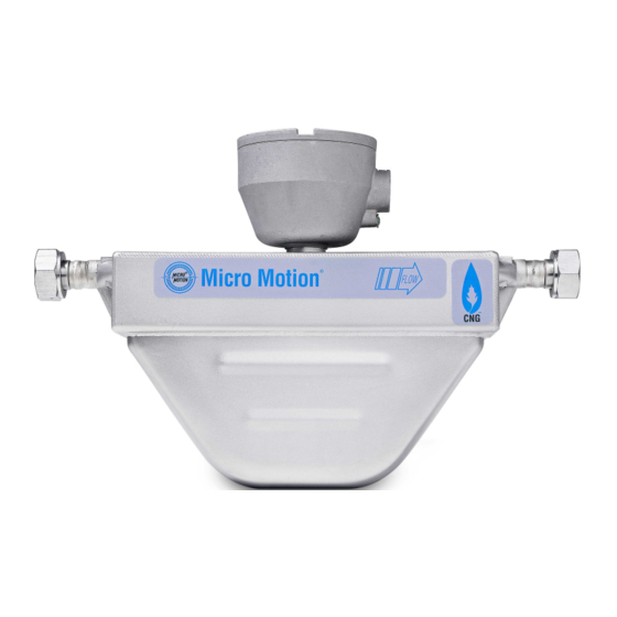
Summary of Contents for Emerson MICROMOTION CNG050
- Page 1 Installation Manual 20002586, Rev BB January 2016 ® Micro Motion CNG050 Sensors...
- Page 2 Micro Motion procedures will result in your equipment being refused delivery. Information on return procedures and forms is available on our web support system at www.micromotion.com, or by phoning the Micro Motion Customer Service department. Emerson Flow customer service Email: •...
-
Page 3: Table Of Contents
Contents Contents Chapter 1 Planning ...........................1 Installation checklist ........................1 Best practices ..........................2 Temperature limits .........................3 Chapter 2 Mounting .........................4 Mount the sensor ........................... 4 Chapter 3 Wiring ..........................5 Options for wiring .......................... 5 Connect 4-wire cable ........................5 Chapter 4 Grounding ........................10 Installation Manual... - Page 4 Contents Micro Motion CNG050...
-
Page 5: Chapter 1 Planning
Planning Planning Topics covered in this chapter: • Installation checklist • Best practices • Temperature limits Installation checklist □ Make sure that the hazardous area specified on the approval tag is suitable for the environment in which the meter will be installed. □... -
Page 6: Best Practices
Planning □ The sensor has a pressure relief feature to evacuate the case in the unlikely event of a loss of primary containment: The pressure relief feature is located underneath the calibration tag. Orient the sensor so that personnel and equipment will not be exposed to escaping pressurized discharge along the pressure relief path. -
Page 7: Temperature Limits
Planning Temperature limits Sensors can be used in the process and ambient temperature ranges shown in the temperature limit graphs. For the purposes of selecting electronics options, temperature limit graphs should be used only as a general guide. If your process conditions are close to the gray area, consult with your Micro Motion representative. -
Page 8: Chapter 2 Mounting
Mounting Mounting Mount the sensor Use your common practices to minimize torque and bending load on process connections. To reduce the risk of condensation problems, do not orient transmitters or sensor junction boxes with their conduit openings pointing upward. CAUTION! Do not lift the sensor by the electronics. -
Page 9: Chapter 3 Wiring
Wiring Wiring Topics covered in this chapter: • Options for wiring • Connect 4-wire cable Options for wiring The wiring procedure you follow depends on which electronics option you have. Table 3-1: Wiring procedures by electronics option Electronics option Wiring procedure Integral transmitter The transmitter is already connected to the sensor. - Page 10 Wiring The 4-wire cable supplied by Micro Motion consists of one pair of red and black 18 AWG (0.75 mm ) wires for the VDC connection, and one pair of white and green 22 AWG (0.35 mm ) wires for the RS-485 connection. User-supplied 4-wire cable must meet the following requirements: •...
- Page 11 Wiring Figure 3-1: 4-wire cable preparation Remove the core processor cover Cable layout Cable glands Metal conduit Gland supplier Run conduit to Micro Motion User-supplied sensor cable gland cable gland Pass the wires through the gland nut and clamping insert. Lay cable in conduit Pass the wires Gland nut...
- Page 12 Wiring Figure 3-2: 4-wire cable shielding From the preparation procedure Micro Motion User-supplied Gland supplier cable gland cable gland Cable shield Foil Braided type (shielded cable) (armored cable) Gland type Trim 7 mm from the shielded heat shrink Apply the Heat Shrink 1.
- Page 13 Wiring Figure 3-3: Core processor terminals From Step 1 or 2 Connect the wires to the core processor terminals: Red wire > Terminal 1 (Power supply +) Black wire > Terminal 2 (Power supply –) White wire > Terminal 3 (RS-485/A) Green wire >...
-
Page 14: Chapter 4 Grounding
Grounding Grounding The meter must be grounded according to the standards that are applicable at the site. The customer is responsible for knowing and complying with all applicable standards. Prerequisites Micro Motion suggests the following guides for grounding practices: • In Europe, IEC 79-14 is applicable to most installations, in particular Sections 12.2.2.3 and 12.2.2.4. - Page 15 Grounding Installation Manual...
- Page 16 © Micro Motion Japan 2016 Micro Motion, Inc. All rights reserved. Emerson Process Management The Emerson logo is a trademark and service mark of Emerson 1-2-5, Higashi Shinagawa Electric Co. Micro Motion, ELITE, ProLink, MVD and MVD Direct Shinagawa-ku Connect marks are marks of one of the Emerson Process Tokyo 140-0002 Japan Management family of companies.


Need help?
Do you have a question about the MICROMOTION CNG050 and is the answer not in the manual?
Questions and answers