
Related Manuals for Emerson Micro Motion H Series


Summary of Contents for Emerson Micro Motion H Series
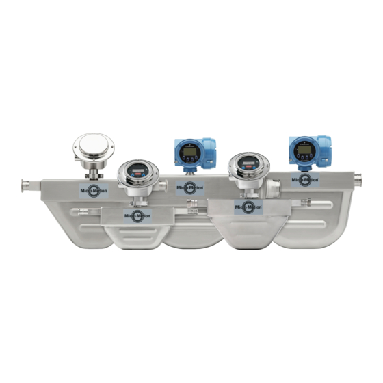
- Page 1 Installation Manual 20002346, Rev BC January 2019 ® Micro Motion H-Series Hygienic Coriolis Flow and Density Sensors...
- Page 2 Micro Motion employees. Micro Motion will not accept your returned equipment if you fail to follow Micro Motion procedures. Return procedures and forms are available on our web support site at www.emerson.com, or by phoning the Micro Motion Customer Service department.
-
Page 3: Table Of Contents
Installation Manual Contents 20002346 January 2019 Contents Chapter 1 Planning........................5 1.1 Installation checklist......................... 5 1.2 Best practices........................... 6 1.3 Temperature limits...........................6 1.4 Recommendations for hygienic and self-draining applications............7 Chapter 2 Mounting........................9 2.1 Mount the sensor..........................9 2.2 Attach extended electronics......................10 Chapter 3 Transmitter power and I/O wiring................ - Page 4 Contents Installation Manual January 2019 20002346 Micro Motion H-Series...
-
Page 5: Chapter 1 Planning
Installation Manual Planning 20002346 January 2019 Planning Installation checklist □ Make sure that the hazardous area specified on the approval tag is suitable for the environment in which the meter will be installed. □ Verify that the local ambient and process temperatures are within the limits of the meter. -
Page 6: Best Practices
Planning Installation Manual January 2019 20002346 Table 1-3: Preferred sensor orientation (continued) Gases Slurries and self-draining applications □ Install the meter so that the flow direction arrow on the sensor case matches the actual forward flow of the process. (Flow direction is also software-selectable.) Best practices The following information can help you get the most from your sensor. -
Page 7: Recommendations For Hygienic And Self-Draining Applications
Installation Manual Planning 20002346 January 2019 • The extended-mount electronics option allows the sensor case to be insulated without covering the transmitter, core processor, or junction box, but does not affect temperature ratings. When insulating the sensor case at elevated process temperatures (above 140 °F (60.0 °C)), please ensure electronics are not enclosed in insulation as this may lead to electronics failure. - Page 8 Planning Installation Manual January 2019 20002346 Figure 1-1: Installation for self-draining applications A. Process pipeline B. Direction of normal process flow C. Direction of drainage Micro Motion H-Series...
-
Page 9: Chapter 2 Mounting
Installation Manual Mounting 20002346 January 2019 Mounting Mount the sensor Use your common practices to minimize torque and bending load on process connections. About this task To reduce the risk of condensation problems, do not orient transmitters or sensor junction boxes with their conduit openings pointing upward. -
Page 10: Attach Extended Electronics
Mounting Installation Manual January 2019 20002346 Attach extended electronics If your installation has a sensor with extended electronics, you will need to install the extender onto the sensor case. About this task Note Extended core processors are matched at the factory to specific sensors. Keep each core processor together with the sensor with which it was shipped. - Page 11 Installation Manual Mounting 20002346 January 2019 4. Fit the extender onto the feedthrough by carefully aligning the notches on the bottom of the extender with the notches on the feedthrough. 5. Close the clamping ring and tighten the clamping screw to 13 in lbf (1.47 N m) to 18 in lbf (2.03 N m).
- Page 12 Mounting Installation Manual January 2019 20002346 Micro Motion H-Series...
-
Page 13: Transmitter Power And I/O Wiring
Installation Manual Transmitter power and I/O wiring 20002346 January 2019 Transmitter power and I/O wiring Options for wiring The wiring procedure you follow depends on which electronics option you have. Table 3-1: Wiring procedures by electronics option Electronics option Wiring procedure Integral transmitter The transmitter is already connected to the sensor. - Page 14 Transmitter power and I/O wiring Installation Manual January 2019 20002346 • Twisted pair construction. • Applicable hazardous area requirements, if the core processor is installed in a hazardous area. • Wire gauge appropriate for the cable length between the core processor and the transmitter, or the host.
- Page 15 Installation Manual Transmitter power and I/O wiring 20002346 January 2019 A. Gland nut B. Clamping insert 3. Strip the cable jacket. Option Description NPT gland type Strip 4.5 in (114 mm) M20 gland type Strip 4.25 in (108 mm) 4. Remove the clear wrap and filler material. 5.
- Page 16 Transmitter power and I/O wiring Installation Manual January 2019 20002346 Option Description Trim 0.3 in (8 mm). gland type A. Trim 8. Assemble the gland by folding the shield or braid back over the clamping insert and 0.125 in (3 mm) past the O-ring. A.
-
Page 17: Connect The 9-Wire Cable
Installation Manual Transmitter power and I/O wiring 20002346 January 2019 Connect the 9-wire cable Procedure 1. Prepare and install the cable according to the instructions in the Micro Motion 9-Wire Flowmeter Cable Preparation and Installation Guide. 2. Insert the stripped ends of the individual wires into the terminal blocks of the junction box. - Page 18 Transmitter power and I/O wiring Installation Manual January 2019 20002346 Micro Motion H-Series...
-
Page 19: Chapter 4 Grounding
Installation Manual Grounding 20002346 January 2019 Grounding The meter must be grounded according to the standards that are applicable at the site. The customer is responsible for knowing and complying with all applicable standards. Prerequisites Use the following guides for grounding practices: •... - Page 20 Grounding Installation Manual January 2019 20002346 Micro Motion H-Series...
-
Page 21: Chapter 5 Supplementary Information
Installation Manual Supplementary information 20002346 January 2019 Supplementary information Purge the sensor case Prerequisites Make sure the following are available before beginning the purge procedure: ™ • Teflon tape • Argon or nitrogen gas sufficient to purge the sensor case About this task Whenever a purge plug is removed from the sensor case, you must repurge the case. - Page 22 Supplementary information Installation Manual January 2019 20002346 • If the purge gas is lighter than air (such as nitrogen), locate the inlet higher than the outlet, so that the purge gas will displace air from top to bottom. 5. Make sure that there is a tight seal between the inlet connection and sensor case, so that air cannot be drawn by suction into the case or purge line during the purging process.
- Page 23 Installation Manual 20002346 January 2019 Installation Manual...
- Page 24 © 2019 Micro Motion, Inc. All rights reserved. The Emerson logo is a trademark and service mark of Emerson Electric Co. Micro Motion, ELITE, ProLink, MVD and MVD Direct Connect marks are marks of one of the Emerson Automation Solutions family of companies. All other marks are property of their respective owners.
Need help?
Do you have a question about the Micro Motion H Series and is the answer not in the manual?
Questions and answers