
Subscribe to Our Youtube Channel
Related Manuals for Emerson Net Safety Millennium II SC310


Summary of Contents for Emerson Net Safety Millennium II SC310
- Page 1 Safety Manual 00809-0100-4310, Rev AA May 2021 Millennium II SC310 Combustible Gas Sensor...
- Page 2 Emerson does not assume any liability arising out of the application or any use of any product or circuit described herein;...
- Page 3 SHALL INCLUDE, BUT NOT BE LIMITED TO, LOSS OF ANTICIPATED PROFITS, REVENUE OR USE AND COSTS INCURRED INCLUDING WITHOUT LIMITATION FOR CAPITAL, FUEL AND POWER, AND CLAIMS OF BUYER'S CUSTOMERS. Contact information Emerson Toll Free + 866 347 3427 6021 Innovation Blvd.
- Page 5 This manual has been designed to ensure the sensor is set-up, operated and maintained properly. It outlines specific details of the Catalytic Bead sensor and addresses calibration procedures using the Millennium II Basic Transmitter and the Millennium II Transmitter. If you encounter any problems, see Troubleshooting or contact Emerson representative. Net Safety SC310...
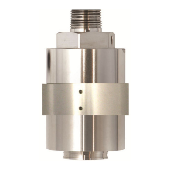
- Page 6 Figure 1-1: Dimensional drawing for Sensor with Millennium II Series Transmitters Table 1-1: Millennium II Enclosure and Sensor Dimensions (A through H) in Inches (in) and Millimeters (mm) Millennium transmitter enclosure Transmitter and sensor (AL) Transmitter and sensor (SS) Emerson.com/Rosemount...
- Page 7 Safety Manual Introduction 00809-0100-4310 May 2021 Table 1-2: Millennium II Basic Enclosure (or Junction Box Enclosure) and Sensor Dimensions (A through J) in Inches (in) and Millimeters (mm) Millennium II basic and sensor Transmitter and sensor(AL) Transmitter and sensor(SS) Millennium II basic and sensor Transmitter and sensor (AL)
- Page 8 Introduction Safety Manual May 2021 00809-0100-4310 Emerson.com/Rosemount...
-
Page 9: Locate Sensor
Safety Manual Plan 00809-0100-4310 May 2021 Plan Locate sensor Prior to the installation process, develop a plan. Although there are no absolute rules determining the quantity of detectors or location of a sensor, consider the following points when planning the installation. •... - Page 10 Calibration gas can then be applied from ground level. Emerson.com/Rosemount...
- Page 11 Safety Manual Plan 00809-0100-4310 May 2021 To compensate for the effect of distance when remotely calibrating, in separation configuration, decrease the tubing diameter or increase the calibration gas flow rate between the gas canister and sensor. On initial install, always confirm tubing run is not affecting calibration.
- Page 12 Plan Safety Manual May 2021 00809-0100-4310 Emerson.com/Rosemount...
-
Page 13: Unpack And Inspect
Carefully remove all the components from the packaging and check them against the enclosed packing list. Inspect all components for any obvious damage such as broken or loose parts. If you find any components missing or damaged, notify your local Emerson representative or the factory immediately. Mount Ensure the transmitter and sensor are securely mounted as per local regulations. - Page 14 Sensors may also be mounted remotely from transmitters using certified junction boxes with designated terminals. Transmitter and junction box enclosures are shipped with one stopping plug fitted and tightened to a ¾-in. NPT conduit entry. Emerson.com/Rosemount...
-
Page 15: Installation Checklist
Safety Manual Installation 00809-0100-4310 May 2021 3.3.2 Wire sensor WARNING Do not open enclosures in a classified area (Do not open when an explosive atmosphere may be present). Ensure the power to the transmitter is switched off before connecting sensor wires. Avoid touching electronic components, as they are susceptible to electrostatic discharge (ESD). - Page 16 Installation Safety Manual May 2021 00809-0100-4310 Emerson.com/Rosemount...
-
Page 17: Operation
Safety Manual Operation 00809-0100-4310 May 2021 Operation Configuration settings All configuration settings are accessed through the Millennium II series transmitters. This is done by setting DIP switches on the Millennium II Basic Transmitter and by selecting menu options in the Millennium II Transmitter. Some configurations are done by the ®... - Page 18 May 2021 00809-0100-4310 disruption of its calibration. As an extra safety precaution, the system should be checked for accuracy after such over-range exposure and if necessary re-calibrated. The system will need to be reset to clear the latched output. Emerson.com/Rosemount...
-
Page 19: Modbus Registers
Safety Manual Output 00809-0100-4310 May 2021 Output Alarm and fault outputs Sensor alarm and fault outputs are generated by the Millennium II series transmitters based on communication with sensors, however some output values, registers, etc, may vary depending on sensor type. The default alarm levels (point) for the sensor are: 20 percent for the low level and 40 percent for the high level. - Page 20 Output Safety Manual May 2021 00809-0100-4310 Emerson.com/Rosemount...
-
Page 21: Calibration Procedure
Safety Manual Maintaining 00809-0100-4310 May 2021 Maintaining Calibration procedure There are specific steps to be followed when calibrating with the Millennium II Basic and the Millennium II Transmitters. These steps should be followed if accurate results are to be obtained. The calibration of Catalytic Bead sensors requires the presence of oxygen. An air balanced calibration gas should be used for calibration, otherwise these sensors will not calibrate properly. - Page 22 Millennium II Basic Transmitter manual calibration procedure below and/or Figure 6-1 before attempting calibration. Millennium II Basic Transmitter Normal Calibration Procedure Calibrations may be performed either by using the magnet (non – intrusive) or by using the push button (intrusive). Emerson.com/Rosemount...
- Page 23 Safety Manual Maintaining 00809-0100-4310 May 2021 Procedure 1. Confirm successful power up of Transmitter, (green blip/blink of status LED every second: no fault indicated). 2. Bypass any output alarms (recommended). 3. For analog model connect a standard current meter to the transmitter’s Test Jacks (not required but gives visual confirmation).
- Page 24 6-1: Calibration Flow chart for Millennium II Basic Transmitter on next page for additional reference. Figure 6-1: Calibration Flow Chart for Millennium II Basic Transmitter Note See the Millennium II Basic transmitter manual when locating calibration switch (push button) or magnetic switch. Emerson.com/Rosemount...
- Page 25 Safety Manual Maintaining 00809-0100-4310 May 2021 6.1.2 Calibrating with the Millennium II Transmitter The following procedures are specific to this controller and should be followed to ensure accurate calibration and detection of gases. The transmitter also offers some flexibility in the use of calibration gas.
- Page 26 7. Apply clean air when “Apply Clean Air” is displayed, then select “Z & Span” using (Menu button 1 or Reed Switch 1) for normal calibration. “Setting zero” will be displayed as the sensor is being zeroed. (Ensure no contaminant gases are present if ambient air is being used). Emerson.com/Rosemount...
- Page 27 Safety Manual Maintaining 00809-0100-4310 May 2021 8. Apply 50% calibration gas (or % Cal. gas value chosen in menu option) when prompted. Recommendation: Flow span gas at a rate of 0.5 liter per minute to the sensor for direct calibrations. If sensor is remotely mounted and long tubing run is used, increase gas flow rate (e.g.
-
Page 28: Cross Sensitivity
Safety Manual May 2021 00809-0100-4310 Figure 6-2: Calibration Flow Chart for Millennium II Transmitter 6.1.3 Cross sensitivity The SC310 sensor will react to airborne materials that burn or explode in oxygen atmospheres, such as gaseous hydrocarbons. Certain compounds, including Halogen- Emerson.com/Rosemount... -
Page 29: Replace Sensor
Safety Manual Maintaining 00809-0100-4310 May 2021 containing hydrocarbons, can reduce sensor response. In some instances this reduction in response is reversible and the sensor will operate normally when such a compound or gas is removed. Exposure to organic phosphates, esters and Silicon-containing compounds will "poison"... -
Page 30: Troubleshooting
See for certified temperatures. Accessories Table 6-3: Available Spare Parts Description Part number Calibration cup/splash guard CCS-1 JB-MPD-A (aluminum) or JB-MPD-S (316 Separation kit stainless steel) Dust filter assembly DSC-1 Replacement cat bead sensor SC310-100 IP66/67 hydrophobic filter IPF-001 Emerson.com/Rosemount... -
Page 31: How To Return Equipment
Safety Manual Maintaining 00809-0100-4310 May 2021 How to return equipment A Material Return Authorization number is required in order to return equipment. Please contact Rosemount at (866) 347-3427, before returning equipment or consult our Service Department to possibly avoid returning equipment. If you are required to return equipment, include the following information: •... - Page 32 Maintaining Safety Manual May 2021 00809-0100-4310 Emerson.com/Rosemount...
-
Page 33: Electrostatic Sensitive Device (Esd)
Safety Manual Electrostatic sensitive device (ESD) 00809-0100-4310 May 2021 Electrostatic sensitive device (ESD) Definition: Electrostatic discharge (ESD) is the transfer, between bodies, of an electrostatic charge caused by direct contact or induced by an electrostatic field. The most common cause of ESD is physical contact. Touching an object can cause a discharge of electrostatic energy—ESD! If the charge is sufficient and occurs near electronic components, it can damage or destroy those components. - Page 34 Electrostatic sensitive device (ESD) Safety Manual May 2021 00809-0100-4310 Emerson.com/Rosemount...
-
Page 35: Resistance Table
Safety Manual Resistance table 00809-0100-4310 May 2021 Resistance table AWG #20 AWG #18 AWG #16 AWG #14 Distance (Feet) 0.5 mm 0.8 mm 1.0 mm 2.0 mm 1.02 0.64 0.40 0.25 2.03 1.28 0.80 0.51 3.05 1.92 1.20 0.76 4.06 2.55 1.61 1.01... - Page 36 Resistance table Safety Manual May 2021 00809-0100-4310 Emerson.com/Rosemount...
- Page 37 Safety Manual Millennium II Catalytic Bead Sensor specifications 00809-0100-4310 May 2021 Millennium II Catalytic Bead Sensor specifications Sensor Specification Performance Power consumption (10.5 – 32 Vdc) < 1.5 W Voltage range 10.5 – 32 Vdc EN50270: 2006 (pending) FM63101/6320 (Radio Frequency Interference) T50 <...
- Page 38 1. Consult the manufacturer if dimensional information on the flameproof joints is necessary 2. The flying leads of the sensors shall be suitably protected against mechanical damage and terminated within a terminal or junction facility suitable for the conditions of use. Emerson.com/Rosemount...
- Page 39 Safety Manual 00809-0100-4310 May 2021 Net Safety SC310...
- Page 40 2021 Emerson. All rights reserved. The Emerson logo is a trademark and service mark of Emerson Electric Co. Net Safety is a mark of one of the Emerson family of companies. All other marks are the property of their respective...
Need help?
Do you have a question about the Net Safety Millennium II SC310 and is the answer not in the manual?
Questions and answers