
Related Manuals for Emerson Micro Motion F Series


Summary of Contents for Emerson Micro Motion F Series
- Page 1 Installation Manual P/N 20002298, Rev. A April 2005 ® Micro Motion F-Series Sensor Installation Manual...
-
Page 2: Table Of Contents
©2005, Micro Motion, Inc. All rights reserved. Micro Motion is a registered trademark of Micro Motion, Inc. The Micro Motion and Emerson logos are trademarks of Emerson Electric Co. All other trademarks are property of their respective owners. Sensor Installation: F-Series... - Page 3 Before You Begin European installations This Micro Motion product complies with all applicable European directives when properly installed in accordance with the instructions in this manual. Refer to the EC declaration of conformity for directives that apply to this product. The EC declaration of conformity, with all applicable European directives, and the complete ATEX Installation Drawings and Instructions are available on the internet at www.micromotion.com/atex or through your local Micro Motion support center.
- Page 4 Before You Begin Figure 1 F-Series sensor with core processor Core processor housing Approval tag Calibration tag Process connection Flow direction arrow Sensor with purge fittings Purge fitting Core processor housing Purge fitting Approval tag Calibration tag Sensor Installation: F-Series...
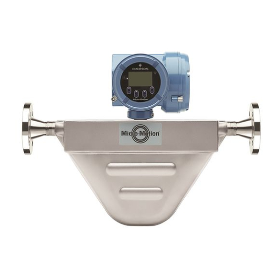
- Page 5 Before You Begin Figure 2 F-Series sensor with integrally mounted Model 1700/2700 transmitter Model 1700 or 2700 transmitter Core processor housing Calibration tag Approval tag Flow direction arrow Process connection Sensor with purge fittings Model 1700 or 2700 transmitter Purge fitting Purge fitting Approval tag Calibration tag...
- Page 6 Before You Begin Figure 3 F-Series sensor with junction box Approval tag Junction box Calibration tag Flow direction arrow Process connection Sensor with purge fittings Purge fitting Junction box Purge fitting Approval tag Calibration tag Sensor Installation: F-Series...
- Page 7 Before You Begin Figure 4 F-Series sensor with integrally mounted IFT9701 transmitter Model IFT9701 transmitter Calibration tag Approval tag Flow direction arrow Process connection Sensor with purge fittings Model IFT9701 transmitter Purge fitting Purge fitting Approval tag Calibration tag Sensor Installation: F-Series...
- Page 8 Before You Begin Figure 5 Model F300A sensor with flexible conduit extended core processor Core processor housing Flexible conduit Length: 36″ (914 mm) Minimum bend radius 2 1/8″ (54 mm) Purge fitting (optional) Approval tag Calibration tag Purge fitting (optional) Flow direction arrow Process connection Sensor Installation: F-Series...
- Page 9 Before You Begin Figure 6 Model F300A sensor with flexible conduit extended Model 1700/2700 transmitter Model 1700 or 2700 transmitter Core processor housing Flexible conduit Length: 36″ (914 mm) Minimum bend radius 2 1/8″ (54 mm) Purge fitting (optional) Approval tag Calibration tag Purge fitting (optional)
- Page 10 Before You Begin Figure 7 Model F300A sensor with flexible conduit extended junction box Junction box Flexible conduit Length: 36″ (914 mm) Minimum bend radius 2 1/8″ (54 mm) Purge fitting (optional) Approval tag Calibration tag Purge fitting (optional) Flow direction arrow Process connection Sensor Installation: F-Series...
-
Page 11: Determining A Location
Determining a Location Step 1 Determining a Location Choose a location for the sensor based on the requirements described in this section. The following general guidelines can help you select an appropriate location for the sensor. • You should be able to stop flow through the sensor to facilitate the zeroing procedure. •... - Page 12 Determining a Location Environmental limits The maximum ambient temperature for the sensor depends on the electronics option: • For F-Series sensors with a junction box or an extended core processor, the maximum ambient temperature is 140 °F (60 °C). • For all Model F300A sensors, the maximum ambient temperature is 140 °F (60 °C). •...
- Page 13 Determining a Location Maximum wiring distances The maximum distance between the sensor and transmitter depends on cable type. See Table 2. Table 2 Maximum cable lengths Cable type Wire size Maximum length Micro Motion 9-wire to an MVD Not applicable 60 feet (20 meters) transmitter or core processor Micro Motion 9-wire to all other...
-
Page 14: Orienting The Sensor
Orienting the Sensor Step 2 Orienting the Sensor The sensor will function properly in any orientation if the sensor tubes remain filled with process fluid. Micro Motion recommends orienting F-Series sensors as shown in Figure 9. Figure 9 Recommended sensor orientations Slurries and Gases Liquids... -
Page 15: Mounting The Sensor
Mounting the Sensor Step 3 Mounting the Sensor Use your common practices to minimize torque and bending load on process connections. Figure 10 illustrates how to mount the sensor. To reduce the risk of condensation or excessive moisture, the conduit opening should not point upward (if possible). - Page 16 Mounting the Sensor Figure 11 Mounting the Model F300A electronics Mounting Mounting bracket bracket (wall mount) (instrument pole) Use 4 × 5/16″ (8 mm) Use 2 × 5/16″ (8 mm) bolts to secure the U-bolts to secure the bracket to a wall bracket to an instrument pole Slide the electronics into the...
-
Page 17: Wiring
Wiring Step 4 Wiring Hazardous area installations If you are installing the sensor in a hazardous location, verify that the hazardous classification information printed on the sensor tag matches the environment in which the sensor will be installed. WARNING Failure to comply with the requirements for intrinsic safety in a hazardous area could result in an explosion. - Page 18 Wiring Core processor to a 4-wire remote transmitter Follow the steps below to connect the 4-wire cable between the core processor and the transmitter. 1. Use one of the following methods to shield the wiring from the core processor to the transmitter: •...
- Page 19 Wiring Figure 13 Wrapping the shield drain wires e. Place the shielded heat shrink over the exposed shield drain wire(s). The tubing should completely cover the drain wires. f. Without burning the cable, apply heat (250 °F or 120 °C) to shrink the tubing. Figure 14 Applying the heat shrink g.
- Page 20 Wiring Figure 16 Gland body and core processor housing 5. Insert the wires through the gland body and assemble the gland by tightening the gland nut. If desired, leave sufficient wire length inside the core processor housing to allow the housing to rotate without damaging the wires.
-
Page 21: Grounding
Grounding Junction box to a 9-wire remote transmitter or remote core processor Follow the steps below to connect the 9-wire cable between the sensor and the transmitter or core processor. 1. Prepare and install the cable according to the instructions in Micro Motion’s 9-Wire Flowmeter Cable Preparation and Installation Guide. -
Page 22: Purge Fittings
Purge Fittings Purge Fittings If the sensor has purge fittings, they should remain sealed at all times. After a purge plug has been removed, the sensor case should be purged with argon or nitrogen and resealed. Purging the case protects internal components. The sensor is purged of all oxygen and sealed at the factory. If the purge plugs are never removed, it is not necessary to purge or re-seal the sensor. - Page 23 Purge Fittings 4. Connect the supply of nitrogen or argon gas to the inlet purge connection or open inlet purge line. Leave the outlet connection open. • Exercise caution to avoid introducing dirt, moisture, rust, or other contaminants into the sensor case.
-
Page 24: Return Policy
Return Policy Return Policy Micro Motion procedures must be followed when returning equipment. These procedures ensure legal compliance with government transportation agencies and help provide a safe working environment for Micro Motion employees. Failure to follow Micro Motion procedures will result in your equipment being refused delivery. - Page 26 +31 (0) 318 495 670 (65) 6777-8211 +31 (0) 318 495 689 (65) 6770-8003 Micro Motion United Kingdom Micro Motion Japan Emerson Process Management Limited Emerson Process Management Horsfield Way Shinagawa NF Bldg. 5F Bredbury Industrial Estate 1-2-5, Higashi Shinagawa Stockport SK6 2SU U.K.
Need help?
Do you have a question about the Micro Motion F Series and is the answer not in the manual?
Questions and answers