Table of Contents
Advertisement
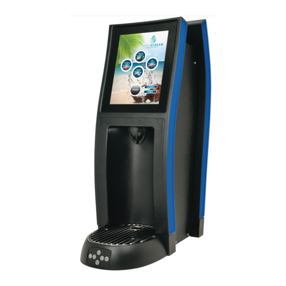
CoCo Fountain Tower
Operation Manual
Lancer Corporation
Tech Support/Warranty: 800-729-1550
6655 Lancer Blvd.
email: custserv@lancercorp.com
San Antonio, Texas 78219
web: lancercorp.com
®
800-729-1500
Lancer PN: 28-3012
320
Revision: August 2018
"Lancer" is the registered trademark of Lancer © 2018 by Lancer, all rights reserved.
Advertisement
Table of Contents

Related Manuals for lancer CoCo Fountain Tower


Summary of Contents for lancer CoCo Fountain Tower
- Page 1 Operation Manual Lancer Corporation Tech Support/Warranty: 800-729-1550 6655 Lancer Blvd. email: custserv@lancercorp.com San Antonio, Texas 78219 web: lancercorp.com ® 800-729-1500 Lancer PN: 28-3012 Revision: August 2018 “Lancer” is the registered trademark of Lancer © 2018 by Lancer, all rights reserved.
-
Page 2: Table Of Contents
The installation and relocation, if necessary, of this product must be carried out by qualified personnel with up-to-date safety and hygiene knowledge and practical experience, in accordance with current regulations. IMPORTANT SAFETY INSTRUCTIONS........3 FEATURES OF THE COCO FOUNTAIN TOWER....13-16 Intended Use.................3 Time & Delay Features............13 Power Warning..............3... -
Page 3: Important Safety Instructions
IMPORTANT SAFETY INSTRUCTIONS ! Intended Use F Power • The dispenser is for indoor use only • Follow all local electrical codes when making connections. • This appliance is intended to be used in commercial • Appliance must be supplied by 24 VDC. applications such as restaurants or similar. -
Page 4: Pre-Installation
PRE-INSTALLATION Specifications & Features 9.2 in 9.7 in 26.9 in A. Touch Screen B. Nozzle 2.1 in C. Splash Plate D. Cup Rest E. Drip Tray 17.1 in F. Ribbon Light PLAIN WATER SUPPLY DIMENSIONS Min Flowing Pressure: 20 psi (0.137 MPa) Width: 9.2 inches (235 mm) Max Static Pressure: 65 psi (0.448 MPa) Depth: 17.1 inches (433 mm) -
Page 5: General System Overview
General System Overview Syrup Line Line Plain Water Line Drain Line Electrical Carb Water Line Carb Water Return A. Water Source B. CO Source C. High Pressure CO Regulator D. Electrical Outlet E. Tower (Dispenser) F. Recirculation Unit G. Syrup Pump H. -
Page 6: Installation
Please read this manual before installation and operation of this dispenser. Please see page 21 for troubleshooting or service assistance. If the service cannot be corrected please call your Service Agent or Lancer Customer Service. Always have your model and serial number available when you call. -
Page 7: Dispenser Installation
Dispenser Installation Using proper lifting techniques, lift the tower over the counter top, then route end of power cord through the opening in the counter. Slide the tower into the cutout in the counter and use the screws and mounting brackets provided to secure the tower to the counter. -
Page 8: Dispenser Setup
NOTE Using a screwdriver, remove the top two screws of the top plate then slide plate back slightly and lift from the front edge Contact Lancer Technical Support for the units’ to remove. designated pin number. A. Top Plate Screw B. - Page 9 13. For manager’s access to the service menu, press and hold the upper, right-hand corner of the screen for a minimum of five (5) seconds and enter the manager’s pin number (6655). NOTE The manager’s access to the service menu allows access to the Lighting screen (see page 15), the Sold Out screen (see page 16), and the Time &...
-
Page 10: Adding New Brand/Flavor Module
Adding New Brand/Flavor Module In order to add a new brand or flavor module, the module Press the Configure button under any of the activated brand must first be activated. or flavor modules to open its Configuration Page. From the Service menu, press the Valve Configuration button. -
Page 11: Calibration And Maintenance
10. Once a brand/flavor has been selected to a corresponding 13. From the Service Menu, press the Maintenance button. module, press the Valve Configuration button to return to the 14. Press the Purge tab on the far left side of the screen. Valve Configuration Screen. -
Page 12: Calibrating Brand Modules
Calibrating Brand Modules NOTE The refrigeration unit should have been running for at least one (1) hour before attempting to set flow rates on valves. The drink temperature should be no higher than 40°F (4.4°C) when flow rates are set. This is best done after the remote chiller has already made an ice bank. (If applicable) From the Service menu, press the Maintenance button. Using a plastic pipette or dropper, drip the sample dispensed in the previous step onto a previously calibrated Press the Calibrate tab on the far left side of the screen and refractometer. -
Page 13: Scheduled Maintenance
Scheduled Maintenance • Keep exterior surfaces of dispenser (include drip tray and cup rest) clean using a clean, damp As Needed cloth. • Clean and sanitize the unit’s nozzle and nozzle injectors using the appropriate procedures out- lined in the Cleaning and Sanitizing Nozzle section of this manual. •... -
Page 14: System Settings
System Settings From the Service menu, press the System button on the top Press and hold the new Nutrition Facts “page curl” at the of the left hand column. bottom of the screen to reveal the nutrition information of the brands/flavors present on the screen (if available). -
Page 15: Lighting Features
Lighting Features From the Service menu, press the Lighting button. From this menu, the user can adjust the Screen Brightness as well as the brightness of the Nozzle Light when the unit is dispensing and when the unit is not dispensing (Idle). A. -
Page 16: Sold Out Features
Sold-Out Feature From the Service Menu, press the Sold Out button. To add the Auto Sold Out feature to a specific brand, simply tap the corresponding intersection to activate a sold out sen- Press the Override tab on the far left side of the screen. sor for that brand. -
Page 17: Data Management
For information on the Tower Brand Management Software visit lancercorp.com, contact your Lancer Customer Service Representative. Visit lancercorp.com and access the Tower Brand Management Software Instruction Sheet (Lancer Part Number: 28-2855/01). Create a USB drive with the created .brand file in a folder named “brands”... -
Page 18: Update Screen Savor Videos
Update Screen Saver Videos Create a USB Drive with the new video file in a folder structure named “images\ss”. NOTE The video file must be in a .mp4 format and the dimensions of the video must be 768 px x 1024 px. Create a .txt file in any editor software (ex: Notepad on Windows machines) that contains the name of the video file and is named “list.txt”... -
Page 19: Update Background Image
General Information • Lancer equipment (new or reconditioned) is shipped from the factory cleaned and sanitized in accordance with NSF guidelines. The operator of the equipment must provide continuous maintenance as required by this manual and/or state and local health department guidelines to ensure proper operation and sanitation requirements are maintained. -
Page 20: Cleaning And Sanitizing Solutions
Cleaning and Sanitizing Solutions Cleaning Solution Sanitizing Solution Mix a mild, non-abrasive detergent (e.g. Sodium Laureth Sulfate, Prepare the sanitizing solution in accordance with the dish soap) with clean, potable water at a temperature of 90°F to manufacturer’s written recommendations and safety guidelines. 110°F (32°C to 43°C). -
Page 21: Troubleshooting
Communication with the dispense controller Check connection between dispense has been lost controller and touchscreen This icon appears on screen: Connection with touchscreen has been Contact Lancer Customer Service for more lost information Water leakage around nozzle. O-ring is damaged or missing. Replace o-ring. - Page 22 TROUBLE CAUSE REMEDY Water only dispensed; no Water or syrup shutoff on mounting block Open shutoff fully. syrup; or syrup only not fully open. Remove valve from mounting block, open dispensed, no water Improper or inadequate water or syrup flow. shutoffs slightly and check water and syrup flow.
- Page 23 TROUBLE CAUSE REMEDY BIB pump does not operate Out of CO , CO not turned on, or low CO Replace CO supply, turn on CO supply, or when dispensing valve opened. pressure. adjust CO pressure to 70-80 psi (0.483- 0.552 MPa) Out of syrup.
-
Page 24: Illustrations And Part Listings
ILLUSTRATIONS AND PART LISTINGS Main Unit Assembly Item Part No. Description 05-3429/01 Drip Tray, TsT 30-11889 Center Panel, Right 23-1726 Cup Rest, TsT 04-1714 Washer, M4 05-3296/01 Splash Plate, TsT 04-1717 Nut, M4 04-0633/01 Screw, 6-19 x 0.437 04-1689/01 Screw, M4 05-3434/01 Drip Tray Bumper, Left 30-11890... -
Page 25: Plumbing Assembly
Plumbing Assembly 16 x5 20 x12 19 x2 09 x4 17 x6 Item Part No. Description 01-2991 Coupling, Female 04-1621 Screw, 4-20 X 0.38, SS, PT 04-1710/01 Washer, Flat 05-4023 Inner Nozzle Body, Mach, CW-TsT 02-0677 Seal, Washer, Drain 02-0214/01 O-Ring, 2-008, 97-1114 01-2994 Drain Fitting, 1/2 NPT... -
Page 26: Electronics Assembly
Electronics Assembly 07 x2 10 x4 08 x2 Item Part No. Description 82-4963/01 Screen Assy, TsT 02-0681 Washer, 0.343 OD X 0.093 04-1714 Washer, Flat, M4 10-1000 Magnet, Neo, Reverse, 0.5 X 0.125 04-1717 Nut, M4 64-5061 PCB Assy, Valve Board 52-3661 Drip Tray Dual Light Assy 64-5104/01... -
Page 27: Unit Plumbing Diagram
Unit Plumbing Diagram Item Description Syrup Line 7 Syrup Line 8 Syrup Line 9 Syrup Line 10 Plain Water Line Soda Line Recirculation Line... -
Page 28: Unit Wiring Diagram
Unit Wiring Diagram... -
Page 29: Counter Cut-Out
5.02 [127.49] 6.19 [157.30] 4.13 [101.71] CUT ALONG 1.62 [41.28] DOTTED LINES Counter Cut-out (To Scale) FRONT OF UNIT... - Page 30 Lancer Corp. 800-729-1500 Technical Support/Warranty: 800-729-1550 custserv@lancercorp.com lancercorp.com...
Need help?
Do you have a question about the CoCo Fountain Tower and is the answer not in the manual?
Questions and answers