Table of Contents
Advertisement
Quick Links
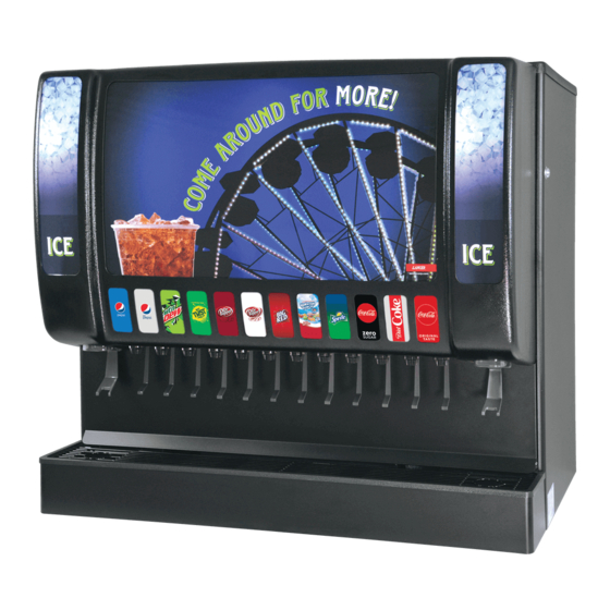
Sensation 44
Operation Manual
Lancer Corporation
Technical Support/Warranty: 800-729-1550
6655 Lancer Blvd.
email: custserv@lancercorp.com
®
San Antonio, Texas 78219
web: lancercorp.com
4900
800-729-1500
Lancer PN: 28-0983/01
Revision: September 2018
"Lancer" is the registered trademark of Lancer © 2018 by Lancer, all rights reserved.
Advertisement
Table of Contents

Related Manuals for lancer Sensation 44


Summary of Contents for lancer Sensation 44
- Page 1 Operation Manual Lancer Corporation Technical Support/Warranty: 800-729-1550 6655 Lancer Blvd. email: custserv@lancercorp.com ® San Antonio, Texas 78219 web: lancercorp.com 4900 800-729-1500 Lancer PN: 28-0983/01 Revision: September 2018 “Lancer” is the registered trademark of Lancer © 2018 by Lancer, all rights reserved.
-
Page 2: Table Of Contents
TABLE OF CONTENTS ABOUT THIS MANUAL BEFORE GETTING STARTED This booklet is an integral and essential part of the product. Each unit is tested under operating conditions and is thoroughly Please carefully read the guidelines and warnings contained inspected before shipment. At the time of shipment, the carrier herein as they are intended to provide the user with essential accepts responsibility for the unit. -
Page 3: Important Safety Instructions
IMPORTANT SAFETY INSTRUCTIONS ! Intended Use F Power • The dispenser is for indoor use only • Follow all local electrical codes when making connections. • This appliance is intended to be used in commercial applications such as restaurants or similar. •... -
Page 4: Automatic Agitation
! Automatic Agitation • Units are equipped with an automatic agitation system and will activate unexpectedly. Do not place hands or foreign objects in the ice bin tank. Unplug the dispenser during servicing, cleaning, and • CAUTION: sanitizing. To avoid personal injury, do not attempt to lift the dispenser without assistance. For heavier dispensers, use a •... -
Page 5: General Systems Overview
BIB SYSTEM: Is counter-top level? Oetiker Clamp Fittings BIB Rack Can the counter-top support the Water Booster (Lancer PN: weight of the dispenser? (Include BIB Syrup Boxes 82-3401 or MC-163172 the weight of an ice machine plus weight of ice, if necessary) -
Page 6: Installation
Read This Manual This manual was developed by Lancer Corporation as a reference guide for the owner/operator and installer of this dispenser. Read this manual before installation and operation of this dispenser. See pages 17-21 for troubleshooting or service assistance. If the service cannot be corrected please call your Service Agent or Lancer Customer Service. -
Page 7: Installing An Icemaker
An adapter plate is required when installing an icemaker. Ensure the icemaker is installed properly to allow for removal of the Merchandiser. Contact your Sales Representative or Lancer Customer Service for more information. Ensure manual fill is accessible. A bin thermostat is required in order to control the level of Clean and maintain icemaker per manufacturer’s... -
Page 8: Merchandiser Installation/Removal
Merchandiser Installation/Removal To remove the merchandiser, first detach the left and right Position the lower edge of the merchandiser over each of side of the merchandiser from the connection tabs by the valve plates. pulling away from the unit. A. Position Over A. -
Page 9: Dispenser Installation
B. Tubing C. Syrup/Water Inlet Connect tubing to water source then flush water lines to check for leaks. If necessary, install water booster (Lancer PN MC-163172) between water supply and the unit. A. Pressure Relief Valve B. CO Inlet... -
Page 10: Installing Co Supply
! ATTENTION 15. Route the power supply cord to a grounded electrical outlet of the proper voltage and amperage rating. Pouring hot water into drain may cause the Drain Tube F WARNING to collapse. Allow only luke warm or cold water to enter Drain Tube. Pouring coffee tea and similar substances DO NOT PLUG UNIT INTO GROUNDED ELECTRICAL into drain may cause the Drain Tube to become OUTLET AT THIS TIME. -
Page 11: Dispenser Setup
! WARNING Connect tubing routed from the tee at the syrup pumps to the second outlet of the low pressure CO regulator DO NOT TURN ON CO SUPPLY AT THIS TIME manifold. A. CO Regulator B. Screwdriver C. Regulator Adjustment Screw A. -
Page 12: Adjust Water Flow Rate & Syrup/Water Ratio
Remove merchandiser. Close syrup shut-off at mounting block for first valve. Using a Lancer ratio cup verify water flow rate (5 oz. in 4 sec.). Use a screwdriver to adjust if needed. A. Syrup Separator B. Soda Lever Re-open syrup shut-off at mounting block. - Page 13 Volumetric Valve Adjustment NOTE The Volumetric Valve is an optional valve for the 44” Sensation dispenser VALVE SPECIFICATIONS 3.0 oz/sec (88.7 ml/sec) Finished Drink Flow Rates 2.25 oz/sec (66.6 ml/sec) 1.5 oz/sec (44.4 ml /sec) Flowing Pressure Requirements MINIMUM MAXIMUM Water 40 psi (0.276 MPa) 110 psi (0.758 MPa) 20 psi (0.138 MPa) 70 psi (0.483 MPa) Syrup 24 VAC, 50/60 Hz...
-
Page 14: Cleaning And Sanitizing
General Information • Lancer equipment (new or reconditioned) is shipped from the factory cleaned and sanitized in accordance with NSF guidelines. The operator of the equipment must provide continuous maintenance as required by this manual and/or state and local health department guidelines to ensure proper operation and sanitation requirements are maintained. -
Page 15: Scheduled Maintenance/Cleaning
Scheduled Maintenance/Cleaning As Needed • Keep exterior surfaces of unit clean using a clean, damp cloth. • Using the cleaning solution, clean top cover and all exterior stainless steel surfaces. • Clean exterior of dispensing valves and ice chute. • Remove cup rest then clean the drip tray and cup rest. -
Page 16: Cleaning And Sanitizing Flavor Injector Nozzles
Cleaning and Sanitizing Flavor Injector Nozzles Disconnect power, so as to not activate valve while Using a soft cloth and the cleaning solution described on cleaning. page 13, thoroughly clean the flavor injector nozzle and bracket of any residual syrup. Disconnect the two (2) lower, horizontal LED light bars and remove from unit. -
Page 17: Ice Chute
12. Remove the four (4) screws from the bracket holding the 19. Remove Auger by pulling straight out from unit and set Auger Motor, flavor injector bracket, and LED light bracket. aside. A. Auger Motor B. Remove Screws A. Auger Motor B. -
Page 18: Cleaning And Sanitizing Syrup Lines
Cleaning and Sanitizing Syrup Lines - Bag in Box Disconnect syrup lines from BIB’s Prepare Sanitizing Solution described above. Place syrup lines, with BIB connectors, in a bucket of warm Place syrup lines into sanitizing solution and activate each water. valve to fill lines with sanitizer. - Page 19 TROUBLE CAUSE REMEDY Push chute, ice door opens but Wiring harness not plugged in. Plug in wiring harness. motor does not run. PC board defective. Replace PC board. Motor defective. Replace motor. Push chute, motor runs but ice Solenoid not connected to PC board. Connect solenoid to PC board.
- Page 20 TROUBLE CAUSE REMEDY Insufficient syrup flow. Insufficient CO pressure to BIB pumps. Adjust CO pressure to BIB pumps to 80 psi (0.552 MPa) (min. 70 psi (0.483 MPa). Shutoff on mounting block not fully open. Do not exceed manufacturer’s Foreign debris in syrup flow control. recommendations.
- Page 21 TROUBLE CAUSE REMEDY Water only dispensed, no Syrup BIB empty. Replace syrup BIB as required. syrup. Or syrup only dispensed, Water or syrup shutoff on mounting block Open shutoff completely. no water. not fully open. Remove valve from mounting block & Improper or inadequate water or syrup open shutoffs slightly.
-
Page 22: Illustrations And Part Listings
TROUBLE CAUSE REMEDY BIB pump fails to restart after BIB connector not on tightly. Tighten BIB connector. bag replacement. BIB connector is stopped up. Clean out or replace BIB connector. Kinks in syrup line. Straighten or replace line. BIB pump fails to stop when Leak in discharge line or fittings. -
Page 23: Main Unit Assembly
Main Unit Assembly Item Part No. Description 82-5207 Drip Tray, IBD44 64-5037/01 Ice Control PCB Assembly 23-1768 Cup Rest 82-4507 Solenoid Door Assembly 52-3701 ADA Membrane Switch 12-0652 LED Driver Ballast, 60 W 30-12681 Splash Plate, 44” Sensation 25-0094 Transformer, 155 VA, 22 VAC 52-3843 Flavor Shot Membrane Switch 05-3468... -
Page 24: Flavor Box Assembly
Flavor Box Assembly Item Part No. Description 82-5174 Flavor Shot Box Assembly, 44” Sensation 64-5123/01 PCB Assembly, Flavor Shot Control Box 19-0523 Valve Assembly, LFCV, 0.2 Syrup Inj. 82-2317/01 Mounting Block Assembly... -
Page 25: Unit Plumbing Diagram
Unit Plumbing Diagram Flavor Shot Box Plumbing Diagram... - Page 26 Wiring Diagram - 115 Volt...
- Page 27 Wiring Diagram - 220-240 Volt...
-
Page 28: Dip Switch Legend
7 SECONDS MODEL 4900 SW1 SWITCH 2: NOT USED FOR 5 SECONDS MODEL 4900 *= DENOTES DEFAULT LANCER PN: 06-3289/01 NOTE If installing a Scotsman Pellet icemaker, set the auto agitation time to every 60 minutes. ® Dispenser Disposal To prevent possible harm to the environment from improper disposal, recycle the unit by locating an authorized recycler or contact the retailer where the product was purchased. - Page 30 Lancer Corp. 800-729-1500 Technical Support/Warranty: 800-729-1550 custserv@lancercorp.com lancercorp.com...
Need help?
Do you have a question about the Sensation 44 and is the answer not in the manual?
Questions and answers