Table of Contents
Advertisement
Quick Links
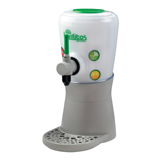
Barrilitos Beverage Tower
Operation Manual
Lancer Corporation
Tech Support/Warranty: 800-729-1550
6655 Lancer Blvd.
email: custserv@lancercorp.com
®
San Antonio, Texas 78219
web: lancercorp.com
330
800-729-1500
Lancer PN: 28-1004/02
Revision: August 2018
"Lancer" is the registered trademark of Lancer © 2018 by Lancer, all rights reserved.
Advertisement
Table of Contents

Related Manuals for lancer Barrilitos Beverage Tower


Summary of Contents for lancer Barrilitos Beverage Tower
- Page 1 Operation Manual Lancer Corporation Tech Support/Warranty: 800-729-1550 6655 Lancer Blvd. email: custserv@lancercorp.com ® San Antonio, Texas 78219 web: lancercorp.com 800-729-1500 Lancer PN: 28-1004/02 Revision: August 2018 “Lancer” is the registered trademark of Lancer © 2018 by Lancer, all rights reserved.
-
Page 2: Table Of Contents
TABLE OF CONTENTS ABOUT THIS MANUAL BEFORE GETTING STARTED This booklet is an integral and essential part of the product. Each unit is tested under operating conditions and is thoroughly Please carefully read the guidelines and warnings contained inspected before shipment. At the time of shipment, the carrier herein as they are intended to provide the user with essential accepts responsibility for the unit. -
Page 3: Important Safety Instructions
IMPORTANT SAFETY INSTRUCTIONS ! Intended Use F Power • The dispenser is for indoor use only • Follow all local electrical codes when making connections. • This appliance is intended to be used in commercial applications such as restaurants or similar. •... -
Page 4: Pre-Installation
PRE-INSTALLATION Specifications & Features 22.75 in. A. Brand Select B. Pour Handle 15.5 in. C. Nozzle 10.0 in. D. Front Panel E. Cup Rest F. Drip Tray DIMENSIONS PLAIN WATER SUPPLY Width: 10.00 inches (254 mm) Min Flowing Pressure: 25 psi (0.172 MPa) Depth: 15.50 inches (393.7 mm) Max Static Pressure: 65 psi (0.448 MPa) Height: 22.75 inches (577.85 mm) -
Page 5: General System Overview
Beverage Tubing Conditioning Ducts Drill Oetiker Clamp Fittings Do you have enough space to install the dispenser? BIB SYSTEM: Water Booster (Lancer PN: 82-3401 or MC-163172 Does the counter height meet BIB Rack ADA requirements? BIB Syrup Boxes Is countertop level? -
Page 6: Installation
Read This Manual This manual was developed by Lancer Corporation as a reference guide for the owner/operator and installer of this dispenser. Please read this manual before installation and operation of this dispenser. Please see pages 13-15 for troubleshooting or service assistance. -
Page 7: Dispenser Installation
Dispenser Installation NOTE Route appropriate tubing from the syrup pump location to the syrup inlets on the tower. Connect tubing to inlets using The installation, and relocation if necessary, must the oetiker pliers and fittings. Repeat for all syrup be carried out by qualified personnel with up-to-date connections. -
Page 8: Adjust Water Flow Rate & Syrup/Water Ratio
If a drain line is to be utilized, place gasket at the bottom of 11. Route power cord either up through designated counter the drain then attach drain fitting to drip tray. cutout or through back panel, (See step 5) and connect power cord to unit control board connection. -
Page 9: Modes Of Operation
Use a screwdriver to adjust the flow if needed, (See Perform a 8 second syrup pour (see page 10) of the first plumbing diagram on page 19 for reference). Repeat Steps syrup line and using a graduated cylinder, verify syrup flow 3-5 until proper flow of water is achieved. -
Page 10: Technician Mode
Technician Mode Technician mode can only be entered within one (1) minute after startup. If the unit has been powered on for more than one minute, cycle power then begin the process to enter the Technician Mode. Press and hold the top two brand buttons simultaneously for two (2) seconds. •... -
Page 11: Led Saver Mode
General Information • Lancer equipment (new or reconditioned) is shipped from the factory cleaned and sanitized in accordance with NSF guidelines. The operator of the equipment must provide continuous maintenance as required by this manual and/or state and local health department guidelines to ensure proper operation and sanitation requirements are maintained. -
Page 12: Scheduled Maintenance & Cleaning
Using a soft, clean cloth, sanitize the nozzle injectors and cleaning solution described on previous page. let air dry. Using the nozzle brush (Lancer PN: 22-0017) included with 10. Reconnect nozzle. the unit and cleaning solution described on the previous page, thoroughly clean the vent located on the nozzle. -
Page 13: Cleaning & Sanitizing Syrup Lines - Bib
Cleaning and Sanitizing Syrup Lines - BIB Disconnect syrup lines from BIB’s Prepare Sanitizing Solution described above. Place syrup lines, with BIB connectors, in a bucket of warm Place syrup lines into sanitizing solution and activate each water. valve to fill lines with sanitizer. Let sit for ten (10) minutes. Activate each valve to fill the lines with warm water and 10. - Page 14 TROUBLE CAUSE REMEDY No syrup dispensed Water and syrup shutoffs on mounting Open shutoff fully. block not fully open. Check electric current supplied to valve. Electric current not reaching valve. If current is adequate, check solenoid coil and switch, and replace if necessary. Improper or inadequate water or syrup supply.
- Page 15 TROUBLE CAUSE REMEDY Circuit breaker tripping. Valve wire harness shorted to itself or to Detect short by disconnecting input fasten faucet plate. to keylock and single pin connector. Restore power if breaker doesn’t trip. PCB is bad. Then valve wire harness is shorted. If OK, Secondary wire harness is bad.
-
Page 16: Illustrations & Part Listings
ILLUSTRATIONS AND PART LISTINGS Main Unit Assembly 13 x4 12 x4 Item Part No. Description 30-13230 Cup Rest, BBT 19-0560 Valve Assy, CVM, Water, 2.0 oz 01-2994 Drain Fitting, 1/2 NPT 19-0559 Valve Assy, CVM, Syrup, 2.0 oz 02-0677 Seal, Washer, Drain 82-2317/01 Mounting Block Assy 54-0554... -
Page 17: Faucet Housing Assembly
Faucet Housing Assembly Item Part No. Description 05-3756 Faucet Handle, BBT 05-3757 Faucet Cam, BBT 10-1019 Actuator Pin 04-0549 Screw, 6-19 x 0.625 05-3765 Washer 05-3759 Upper Faucet Housing, BBT 03-0530 Faucet Spring 82-5297 Actuator Assembly w/ Magnet 64-5028 PCB Assembly, Hall Sensor 04-0699 Screw, 6-19 x 0.250... -
Page 18: Button Panel Assembly
Button Panel Assembly 01 x4 Item Part No. Description 04-1639/01 Screw, 4-20 x 0.250 52-3956 Buttons Harness, BBT 05-3726 Button Panel, BBT 82-5298 Button PCB Assembly... -
Page 19: Wiring Diagram
Wiring Diagram... -
Page 20: Dip Switch Settings
DIP Switch Settings NOTE The following table shows the DIP switch settings that correlate the 16 colors and Barrilitos brand names available on the Barrilitos Tower. DIP Switch Config Color/Brand Name Mango Lime **Switch 1 Default Position** Pear Cucumber **Switch 2 Default Position** Pineapple **Switch 3 Default Position** Strawberry Hibiscus... -
Page 21: Plumbing Diagram
Plumbing Diagram Item Description Syrup Line 1 Syrup Line 2 Syrup Line 3 Syrup Line 4 Plain Water Line Dispenser Disposal To prevent possible harm to the environment from improper disposal, recycle the unit by locating an authorized recycler or contact the retailer where the product was purchased. - Page 22 Lancer Corp. 800-729-1500 Technical Support/Warranty: 800-729-1550 custserv@lancercorp.com lancercorp.com...
Need help?
Do you have a question about the Barrilitos Beverage Tower and is the answer not in the manual?
Questions and answers