Table of Contents
Advertisement
Quick Links
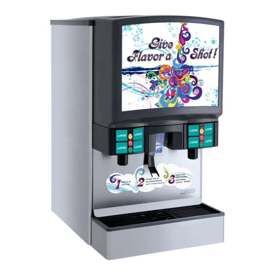
Flavor Select (FS) 22
Ice Beverage Dispenser
Operation Manual
Lancer Worldwide
Tech Support/Warranty: 800-729-1550
6655 Lancer Blvd.
email: custserv@lancerworldwide.com
®
San Antonio, Texas 78219
web: lancerworldwide.com
FS22
800-729-1500
Lancer PN: 28-0580/04
Revision: 04-6 - 4/8/21
"Lancer" is the registered trademark of Lancer © 2019 by Lancer, all rights reserved.
Advertisement
Table of Contents
Troubleshooting

Related Manuals for lancer Flavor Select 22


Summary of Contents for lancer Flavor Select 22
- Page 1 Lancer Worldwide Tech Support/Warranty: 800-729-1550 6655 Lancer Blvd. email: custserv@lancerworldwide.com ® San Antonio, Texas 78219 web: lancerworldwide.com FS22 800-729-1500 Lancer PN: 28-0580/04 Revision: 04-6 - 4/8/21 “Lancer” is the registered trademark of Lancer © 2019 by Lancer, all rights reserved.
-
Page 2: Table Of Contents
Adjust Syrup/Water Ratio..........12-13 Main Unit Assembly............24-25 Ice Chute Assembly..............26 Pellet Ice Bin Assembly - Conversion Kit PN: 82-6285..27 Lancer Flow Control Valve (LFCV)........28 Plumbing Diagram...............29 Wiring Diagram - FS22 115V..........30 Wiring Diagram - FS22 7-11 International 230V....30 Counter Cut-out Diagram.............31 READ ALL SAFETY INSTRUCTIONS BEFORE USING THIS UNIT. -
Page 3: Important Safety Instructions
IMPORTANT SAFETY INSTRUCTIONS ! Intended Use F Power • Follow all local electrical codes when making • The dispenser is for indoor use only connections. • This appliance is intended to be used in commercial • Check the dispenser name plate label, located on the applications such as restaurants or similar. -
Page 4: Automatic Agitation
! Automatic Agitation • Units are equipped with an automatic agitation system and will activate unexpectedly. • CAUTION: Do not place hands or foreign objects in the ice bin tank. Unplug the dispenser during servicing, cleaning, and sanitizing. • CAUTION: To avoid personal injury, do not attempt to lift the dispenser without assistance. -
Page 5: General Systems Overview
BIB SYSTEM: Is countertop level? Oetiker Clamp Fittings BIB Rack Can the countertop support the Water Booster (Lancer PN: weight of the dispenser? (Include BIB Syrup Boxes 82-3401 or MC-163172 the weight of an ice machine plus weight of ice, if necessary) -
Page 6: Installation
Read This Manual This manual was developed by Lancer Worldwide as a reference guide for the owner/operator and installer of this dispenser. Please read this manual before installation and operation of this dispenser. See pages 19 - 23 for troubleshooting or service assistance. -
Page 7: Selecting/Preparing A Counter Location
Select a level, well ventilated location that is in close proximity to a properly grounded electrical outlet, within five Lancer does NOT recommend the use of shaved or (5) feet (1.5 m) of a drain, a water supply that meets the flake ice in this dispenser. -
Page 8: Dispenser Installation
Connect tubing to water source then flush water lines to check for leaks. 10. Install water regulator and filter to water line and, if A. Merchandiser necessary, install water booster (Lancer PN MC-163172) B. Splash Plate between water supply and the unit. C. Drip Tray... - Page 9 11. Using tubing cutters, cut carbonated water line and install 18. Attach BIB connectors on syrup supply line to BIB. Repeat remote pump deck per manufacturer’s specifications, (see for each syrup line/pump. General System Overview on page 5 for reference). 12.
-
Page 10: Installing Co Supply
Installing CO Supply Connect high pressure CO regulator assembly to CO Install tee fitting to CO line and route additional line to CO cylinder or bulk system. regulator at syrup pumps. ! ATTENTION ! ATTENTION Before installing regulator, assure that a seal (washer A dedicated CO regulator is required to supply the or o-ring) is present in regulator attachment nut. -
Page 11: Dispenser Setup
Dispenser Setup Turn on water source. A. CO Regulator B. Regulator Knob Place enough ice in the ice bin to fill approximately 1/2 of the bin before plugging in the unit. Connect unit power cord to grounded electrical outlet. ! WARNING The dispenser must be properly electrically grounded to avoid serious injury or fatal electrical shock. -
Page 12: Adjust Syrup/Water Ratio
C. Pin Latch 15. Repeat Step 13 - 14 until flow rate is correct. 13. Using a Lancer ratio cup, activate the plain water valve to 16. Repeat Steps 13 - 15 for remaining plain and carbonated verify water flow rate (5 oz. in 4 sec.). -
Page 13: Cleaning And Sanitizing
General Information • Lancer equipment (new or reconditioned) is shipped from the factory cleaned and sanitized in accordance with NSF guidelines. The operator of the equipment must provide continuous maintenance as required by this manual and/or state and local health department guidelines to ensure proper operation and sanitation requirements are maintained. -
Page 14: Scheduled Maintenance/Cleaning
6. Make certain that the nozzle o-ring is not torn or otherwise damaged. If necessary, replace damaged o-ring with Lancer PN 02-0231. 7. Wet the inner surface of the nozzle housing with water and reinstall the nozzle housing by sliding it over the nozzle body and turning clockwise to lock in position. -
Page 15: Cleaning And Sanitizing Ice Bin Compartment
Cleaning and Sanitizing Ice Bin Compartment NOTE Remove the gasket which secures the shroud by pulling it out, (See page 6 for reference). Refer to the Automatic Agitation Warning on page 4. Disconnect power to the dispenser Remove Top Cover. Melt out any remaining ice from the bin. -
Page 16: Cleaning And Sanitizing Syrup Lines - Bag In Box
Cleaning and Sanitizing Syrup Lines - Bag in Box NOTE Activate each valve until lines are filled with cleaning solution then let stand for ten (10) minutes. Extended lengths of product lines may require more Flush out cleaning solution from the syrup lines using clean, time to flush and rinse lines. -
Page 17: Operation And Maintenance
Lancer reserves the right to make changes and updates as required. If you have any questions regarding the latest versions of programs, please contact your Lancer representative. The Lancer FS30 has been factory preset to the settings necessary to comply with the brand/flavor version of the unit requested by the customer. -
Page 18: Menus And Sub-Menus
Menus and Sub-Menus Brand Configuration Choose the Valve number (2-3) by scrolling the UP and DOWN arrows. On the Main Menu, use the UP and DOWN arrows to scroll Use the LEFT and RIGHT arrows to shift to the number through the menus and find “FS22 (NO PWB) MAJOR / categories (1-4). -
Page 19: Purging The Carbonation System
Purging the Carbonation System NOTE Turn on the CO supply Turn off the power in order to reconnect the pump harness. Purge the carbonator tank whenever carbonation Turn power back on. issues occur. Dispense soda at valve until the carbonator pump comes on. - Page 20 TROUBLE CAUSE REMEDY Water only dispensed, no Syrup BIB empty. Replace syrup BIB as required. syrup. Or syrup only Water or syrup shutoff on mounting block not Open shutoff completely. dispensed, no water. fully open. Remove valve from mounting block & open Improper or inadequate water or syrup shut offs slightly.
- Page 21 TROUBLE CAUSE REMEDY Insufficient soda flow Insufficient CO supply pressure. Verify incoming CO pressure is between 70 (carbonated drinks). psi (0.483 MPa) and 80 psi (0.552 MPa) Shutoff on mounting block is not fully open. Open shutoff fully. Foreign debris in soda flow control. Remove soda flow control from valve and clean out any foreign material to ensure smooth spool movement.
-
Page 22: Ice Bin/Ice Chute/Carbonator Pump Troubleshooting
Ice Bin/Ice Chute/Carbonator Pump Troubleshooting TROUBLE CAUSE REMEDY Water in ice bin. Cold plate drain is obstructed. Remove splash plate and drip tray to obtain access to drain tubes and clear accordingly. Water leaking from ice door. Securing screws loosened. Tighten screws. -
Page 23: Remote Syrup/Flavor Shot Pump Troubleshooting
Remote Syrup/Flavor Shot Pump Troubleshooting TROUBLE CAUSE REMEDY BIB pump does not operate Out of CO , CO not turned on, or low CO Replace CO supply, turn on CO supply, when dispensing valve is pressure. or adjust CO pressure to 70-80 psi (0.483- opened. -
Page 24: Illustrations And Part Listings
ILLUSTRATIONS AND PART LISTINGS Main Unit Assembly... - Page 25 Part No. Description 85-14408-06-2 IBD, ACMB, 22”, 150#, 8/6, LFCV, Cubed 85-14408N-06-2 IBD, ACMB, 22”, 150#, 8/6, LFCV, Pellet 85-14408-06-2-711 IBD, FS22, 150, 8/6, LED, 115V, 7-11 85-14308-06-711 IBD, FS22, 150, 8/6, 230V, 7-11 85-14308-06-711-47 IBD, FS22, 150, 8/6, 230V, 7-11, THAI Item Part No.
-
Page 26: Ice Chute Assembly
Ice Chute Assembly 7 x2 9 x2 Item Part No. Description 05-2257/01 Upper Ice Chute 05-2905 Lower Ice Chute 05-0999/02 Ice Chute Lever, IBD 04-0268 Screw, 6-19 x 0.625 LG, PLSTI, HHSW/W 03-0241 Ice Chute Spring, IBD 12-0244 Switch, SPST, 5A, 250V, MDM 05-0359/01 Bushing, .123 ID x .187 OD, Nylon 05-0928/02... -
Page 27: Pellet Ice Bin Assembly - Conversion Kit Pn: 82-6285
Pellet Ice Bin Assembly - Conversion Kit PN: 82-6285 Item Part No. Description 42-0109/01 Hoshizaki Pellet Ice Adapter Plate, 30” 30-9880/01 Pellet Ice Shield, 30” 82-3651 Dispensing Wheel Assembly, Pellet Ice 10-0762 Agitator Pin 03-0368 Agitator Pin Retainer 23-1401/01 Helical Agitator Assembly 05-2993/02 Ice Shroud, Bin Liner, 30”... -
Page 28: Lancer Flow Control Valve (Lfcv)
Lancer Flow Control Valve (LFCV) LFCV VALVE ASSEMBLIES: LFCV SPARE PARTS: Item Description Item Part No. Description 82-3820 LFCV, BONUS INJECTOR 10-0870/01 Plug Nut, Solenoid, 2 pack 82-3823 LFCV, 3.0 - 4.5, SYRUP ASSY 02-0538 O-Ring 82-3824 LFCV, 3.0 - 4.5, SODA/WATER ASSY... -
Page 29: Plumbing Diagram
Plumbing Diagram VALVE HARNESS DIAGRAM IS2-1 IS2-2 IS2-3 IS1-3 IS1-2 IS1-1 S2-1 S2-4 S2-3 S1-4 S1-2 S1-1 WATER2 SODA2 S2-2 WATER1 S1-3 SODA1 IS2-1 IS1-1 S1-1 S1- 3 S2-1 S2- 3 IS2-2 IS1-2 S1- 2 S2-2 S2- 4 S1- 4 IS1-3 IS2-3 IS2- 3 IS2- 2 IS2- 1... -
Page 30: Wiring Diagram - Fs22 115V
Wiring Diagram - FS22 115V ICE DOOR SOLENOID BLACK SWITCH WHITE BLACK SWITCH BLACK WHITE BLACK LIGHTING NOTE: TRANSFORMER LED COMMUNICATION LIGHTS FLASH WHEN COMMUNICATING CARB/AGI ICE OPTIC ICE DOOR SOLD OUT COMM SWITCH NOZZLE NOZZLE DISPLAY POWER SUPPLY POWER CONTROLLER CORD GROUND TO... -
Page 31: Counter Cut-Out Diagram
Counter Cutout 22” 15/16” 20 1/8” 23” 18 5/8” 11” 30 1/2” 7 1/2” 3“ DIAMETER OPTIONAL 1 1/2” 3“ F R O N T O F D I S P E N S E R 1 5/8” D R I P T R A Y 7 1/2”... - Page 32 Lancer Worldwide 800-729-1500 Technical Support/Warranty: 800-729-1550 custserv@lancerworldwide.com lancerworldwide.com...
Need help?
Do you have a question about the Flavor Select 22 and is the answer not in the manual?
Questions and answers