Table of Contents
Advertisement
Quick Links
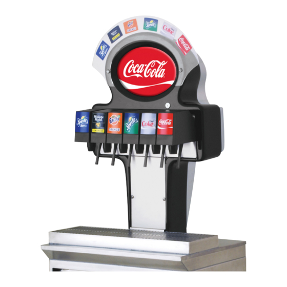
Metal Tower Model 306
Operation Manual
PN: 28-0496/01
Lancer Corp.
6655 Lancer Blvd.
San Antonio, Texas 78219
800-729-1500
Technical Support/Warranty: 800-729-1550
custserv@lancercorp.com
lancercorp.com
Manual PN: 28-0496/01
®
JULY 2001
306
FOR QUALIFIED INSTALLER ONLY
"Lancer" is the registered trademark of Lancer © 2014 by Lancer, all rights reserved.
Advertisement
Table of Contents

Subscribe to Our Youtube Channel
Related Manuals for lancer Metal Tower 306


Summary of Contents for lancer Metal Tower 306
- Page 1 PN: 28-0496/01 Lancer Corp. 6655 Lancer Blvd. San Antonio, Texas 78219 800-729-1500 Technical Support/Warranty: 800-729-1550 custserv@lancercorp.com lancercorp.com Manual PN: 28-0496/01 ® JULY 2001 FOR QUALIFIED INSTALLER ONLY “Lancer” is the registered trademark of Lancer © 2014 by Lancer, all rights reserved.
-
Page 2: Table Of Contents
ABOUT THIS MANUAL This booklet is an integral and essential part of the product and should be handed over to the operator after the installation and preserved for any further consultation that may be necessary. Please read carefully the guidelines and warnings contained herein as they are intended to provide the user with essential information for the continued safe use and maintenance of the product. -
Page 3: Specifications
METAL TOWER SPECIFICATIONS TOWER DIMENSIONS ELECTRICAL PLAIN WATER SUPPLY Width: 18.42 inches (467.8 mm) Tower: 24 V / 60 Hz Min flowing pressure: Depth: 13 inches (330.2 mm) Power Supply: 20 PSI (0.138 MPA) Height: 29 inches (736.6 mm) Input - 115 V / 12 Amps Max flowing pressure: Receptable - 115 V / 10 Amps 50 PSI (0.345 MPA) -
Page 4: Pre-Intallation Checklist
PRE-INSTALLATION CHECKLIST BEFORE GETTING STARTED Each unit is tested under operating conditions and is thoroughly inspected before shipment. At the time of shipment, the carrier accepts responsibility for the unit. Upon receiv- ing the unit, carefully inspect the carton for visible damage. If damage exists, have the car- rier note the damage on the freight bill and file a claim with carrier. -
Page 5: Warnings/Cautions
WARNING/ADVERTENCIA/AVERTISSEMENT The dispenser is for indoor use only. This unit is not a toy. Children should not be supervised not to play with appliance. It should not be used by children or infirm persons without supervision. This appliance is not intended for use by persons (including children) with reduced physical, sensory or mental capabilities, or lack of experience and knowledge, unless they have been given supervision or instruction concerning use of the appliance by a person responsible for their safety. - Page 6 20 PSIG (0.138 MPA). REGLES DE SECURITE POUR L’NSTALLATION DU DISTRIBUTEUR DE SODAS La proprètè da cet ensamable est assurè à I’usine sulvant les spècifications èmis par Lancer . Il est essentiel de respecter les 6 points suivants pour l’installation de l’appareil: 1.
- Page 7 ELECTRICAL WARNING/ADVERTENCIA ELÉCTRICA/ AVERTISSEMENT ÉLECTRIQUE Check the dispenser serial number plate for correct electrical requirements of unit. Do not plug into a wall electrical outlet unless the current shown on the serial number plate agrees with local current available. Follow all local electrical codes when making connections.
- Page 8 WATER NOTICE/AGUA AVISO/ PRÉAVIS DE L’EAU Provide an adequate potable water supply. Water pipe connections and fixtures directly connected to a potable water supply must be sized, installed, and maintained according to federal, state, and local laws. The water sup- ply line must be at least a 3/8 inches (9.525 mm) pipe with a minimum of 20 PSI (0.138 MPA) line pressure, but not exceeding a maximum of 50 PSI (0.345 MPA).
-
Page 9: Installation
1. INSTALLATION UNPACKING A. The Lancer dispenser is shipped in a corrugated shipping carton. B. Remove the corrugated shipping carton from the unit. C. Inspect unit and parts for concealed damage(s). If damage exists, notify delivering carrier and file claim against same. -
Page 10: Electrical Supply
ELECTRICAL SUPPLY (CONTINUED) A. A standard 15 AMP, 110 VAC, 60 Hz, single phase electrical power outlet with a ground connector should be provided for the operation of the unit SYRUP CONTAINERS A. When the unit is used in the Coca-Cola Company installations, the syrup containers are to be attached as outlined in the appropriate Coca-Cola Company Service Manual. -
Page 11: Start Up
(PN 54-0031) in place of nozzle. G. Activate dispensing valve to fill separator syrup tube. H. Hold a Lancer brix cup under the syrup separator and dispense water and syrup into cup for four (4) seconds. Divide number of ounces... -
Page 12: Adjusting Water To Syrup Ratio (Brix)
1.10 ADJUSTING WATER TO SYRUP RATIO (BRIX) A. Hold the Lancer brix cup under the syrup separator and activate valve. Check ratio (brix). B. To obtain the proper ratio, use screw-driver to adjust syrup flow control (see Figure 1). C. Remove syrup separator. -
Page 13: Cleaning And Sanitizing Figal Systems
CLEANING AND SANITIZING SYSTEMS (CONTINUED) 3. Recommended Preparation of Cleaning Solutions. a. Cleaning solutions (for example, Ivory Liquid, Calgon, etc.) mixed with clean, potable water at a temperature of 90 to 110° Fahrenheit should be used to clean equipment. The mixture ratio, using Ivory Liquid, is one (1) ounce of cleanser to two (2) gallons of water. -
Page 14: Cleaning And Sanitizing Bag-In-Box (Bib) Systems
CLEANING AND SANITIZING FIGAL SYSTEMS (CONTINUED) H. Place waste container under applicable dispensing valve. Activate valve and draw cleaning solution through lines for a minimum of 60 seconds. This will ensure line is flushed and filled with cleaning solution. Allow line to stand for at least 30 minutes. NOTE: Extended lengths of product lines may require additional time for flushing and filling lines. -
Page 15: Valves
A. LEV® Valves may be cleaned and sanitized (see preparation in Section 2.2) in the same manner. NOTE: See Lancer Installation and Service Manual 28-0027/03 for complete information on the LEV®. This manual is available on the Lancer web site (www.lancercorp.com). - Page 16 VALVES (CONTINUED) B. Volumetric Valve Cleaning and Sanitizing Procedures NOTE: The Volumetric Valve is an optional use valve with the Global tower. See Lancer Maintenance Manual 28-0301/02 for complete information and adjustment procedures. This manual is available on the Lancer web site (www.lancercorp.com).
- Page 17 For syrup side line priming, and cleaning and sanitization procedures, refer to the Syrup Purge Plug (Lancer PN 52-1912) in Section 2.5.C. C. Syrup Purge Plug (See Figure 3) 1. The Syrup Purge Plug (PN 52-1912), places the valve in continuous syrup side operation.
-
Page 18: Troubleshooting
Check main power circuit breaker 110V. NOTE See Lancer Installation and Service Manual 28-0027/03 for complete troubleshooting information for LEV® valves and/or Lancer Maintenance Manual 28-0301/02 for complete troubleshooting information for the Volumetric Valve. These manuals are available on the Lancer web site (www.lancercorp.com). - Page 19 NOTES...
-
Page 20: Illustrations And Parts Listings
5. ILLUSTRATIONS AND PARTS LISTINGS PACIFIC TOWER... - Page 21 PACIFIC TOWER (CONTINUED) Item Part No. Description 19-0116 LEV® 82-1599 Kit, Label, 6 LEV®, IC, 3-2-1 08-0184 Tubing, Gray, Drain, 5/8” ID 01-1940 Fitting, Drain, 3/4 - 16F X 5/8 BARB, SS 05-1977 Drip Tray, Red, Pacific Tower 30-8407 Plate, Splash, Pacific Tower 04-0585 Screw, M4 X 0.7 X 10, PHD, PH, SST 01-2222...
-
Page 22: Wiring Diagram-Valves
WIRING DIAGRAM - VALVES TO VALVES TO KEY LOCK TO POWER SUPPLY 82-3029 WIRING DIAGRAM FOR VALVES... -
Page 23: Wiring Diagram-Merchandiser
WIRING DIAGRAM - MERCHANDISER FLUORESCENT LAMP INVERTER BALLAST TO POWER SUPPLY 25-0069 WIRING DIAGRAM FOR MERCHANDISER... - Page 24 Lancer Corp. 800-729-1500 Technical Support/Warranty: 800-729-1550 custserv@lancercorp.com lancercorp.com...
Need help?
Do you have a question about the Metal Tower 306 and is the answer not in the manual?
Questions and answers