Table of Contents

Related Manuals for Keysight Technologies N9330B


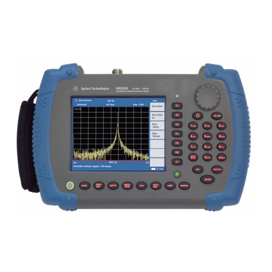
Summary of Contents for Keysight Technologies N9330B
- Page 1 Keysight N9330B Handheld Cable & Antenna Tester Notice: This document contains references to Agilent. Please note that Agilent’s Test and Measurement business has become Keysight Technologies. For more information, go to www.keysight.com. User’s Guide...
- Page 2 COVERING THE MATERIAL IN THIS DOCUMENT THAT CONFLICT WITH government requirements THESE TERMS, THE WARRANTY beyond those set forth in the © Keysight Technologies, Inc. TERMS IN THE SEPARATE EULA shall apply, except to the 2009-2014 AGREEMENT WILL CONTROL. extent that those terms, rights, or...
-
Page 3: Table Of Contents
Electrostatic Discharge (ESD) Precautions Power Requirements Working with Batteries Installing a Battery Viewing Battery Status Your first 10 minutes with the N9330B Power on the N9330B Making the first measurement South Korea Class A EMC Declaration Making Measurements Selecting a Measurement Mode... - Page 4 Measured distance Making an Average Power Measurement Making a Basic Average Power Measurement Figure 3-1. Connection with base station Using Functions Using Markers and Pass/Fail Limit Lines Using markers Using Pass/Fail Limit Lines Processing Traces Trace Operation Trace overlap Saving and Recalling a file Save a trace data Save an instrument setup Copy a screen...
- Page 5 Key Reference AMPTD Bypass Electronic Calibrator Distance Start Stop DTF Config Cable Loss Velocity Factor Cable Window Enter and ESC/CLR Enter ESC/CLR Frequency Start Stop Signal Standard Limit Limit 1 Limit 2 Limit Beep Marker Marker 1...6 Marker All off Meas/View Resolution Single...
- Page 6 Units Language Clock Status Self Test E Calib Test Intelligent License Option Key Light Key Light Edit Light Set Instrument Messages Error Message List Warning List Menu Map FREQ/DIST AMPTD MEAS/VIEW LIMIT Marker Documentation Conventions: 1. A pair of curly brackets { } indicates a softkey, for example {Start} refers to the Start softkey.
-
Page 7: Limit
Overview Overview... -
Page 8: Overview Introduction
Overview Introduction Introduction Keysight has designed the N9330B handheld cable and antenna tester (25 MHz to 4 GHz) to simplify the job of installing and maintaining cable and antenna systems. In addition to measuring SWR, Return Loss and Cable Loss, the N9330B also performs Distance-to-Fault (DTF) - Page 9 Overview Introduction Optimized Usabilities The Keysight N9330B has the following features: • 6.5-inch TFT colorful LCD screen (640×480 pixels) enables you to read the scans easily and clearly outdoors. • Rechargeable lithium-ion battery supports a minimum of four hours continuous operation when fully charged.
-
Page 10: Front Panel Overview
Overview Front Panel Overview Front Panel Overview N9330B 25 M Hz - 4.0 GHz Handheld Cable & Antenna Tester PRT SCR M NO AU TO- SAVE RECALL SCALE ESC/ CLR ENTER FREQ/ M EAS/ HOLD/ M ODE AM PTD LIM IT... -
Page 11: Top Panel Overview
Overview Top Panel Overview Top Panel Overview 23 dBm 50 VDC M AX RF OUT 50 Ext. Pow er Charging 11-25 VDC 55 W M AX Caption Brief Description 1 RF Output Connector Outputs swept signal to DUT (N-type) 2 USB interface Type B (Host) Connects to a PC 3 USB interface Type A Connects to a USB memory stick (Device) -
Page 12: Instrument Markings
Overview Instrument Markings Instrument Markings The CE mark shows that the product complies with all relevant European Legal Directives. The CSA mark is a registered trademark of the Canadian Standards Association. All Level 1, 2 or 3 electrical equipment offered for sale in Australia and New Zealand by Responsible Suppliers must be marked with the Regulatory Compliance Mark. -
Page 13: Getting Started
Getting Started Getting Started... -
Page 14: Checking The Shipment
Getting Started Checking the Shipment Checking the Shipment Check the shipment and order list when you receive the shipment. • Inspect the shipping container for damages. Signs of damage may include a dented or torn shipping container or cushioning material that indicates signs of unusual stress or compacting. -
Page 15: Safety Considerations
Getting Started Safety Considerations Safety Considerations Keysight has designed and tested the N9330B in accordance with IEC Publication 61010-1 Safety Requirements for Electrical Equipment for Measurement, Control and Laboratory Use, and the tester is supplied in a safe condition. Read the following safety notices carefully before you start to use this tester set to ensure safe operation and to maintain the product in a safe condition. - Page 16 Storing a battery in extreme hot or cold places will reduce the capacity and lifetime of a battery. Battery storage is recommended at 25 Always power on the N9330B before connecting an electronic CAU TI O N CAU - calibrator.
-
Page 17: Electrical Requirements
Getting Started Safety Considerations Environmental Requirements Keysight Technologies has designed this tester for use under the following conditions: • Operating temperature: C to 40 C (using AC-DC adapter) –10 C to +50 C (using battery) • Storage temperature: –40 C to +70 •... -
Page 18: Power Requirements
Getting Started Power Requirements Power Requirements The AC power supplied must meet the following requirements Voltage: 100 VAC to 240 VAC Frequency: 47 to 63 Hz Power: Maximum 63 W The AC/DC power supply charger adapter supplied with the analyzer is equipped with a three-wire power cord, in accordance with international safety standards. - Page 19 Getting Started Power Requirements AC Power Cord Plug Type Cable Part For use in Plug Number Country & Region Description 8120-1703 BS 1363/A Option 900 United Kingdom, 250V 10A Hong Kong, Singapore, Malaysia 8120-0696 AS 3112:2000 Option 901 Australia, New 250V 10A Zealand 8120-1692...
-
Page 20: Working With Batteries
Getting Started Working with Batteries Working with Batteries Full charge the battery before first using the analyzer. CAU TI O N CAU - Installing a Battery Step Notes 1 Open the battery cover Use a phillips type screwdriver, loosen the retaining screw, then pull the battery cover open. - Page 21 CAU TI O N CAU - automobile (with option 1DC) for battery recharging. You may recharge the battery in the N9330B while the tester is operating or when it is turned off. 1 Install the battery in the tester. 2 Plug in the correct AC/DC adapter and switch external power on.
-
Page 22: Your First 10 Minutes With The N9330B
Your first 10 minutes with the N9330B Your first 10 minutes with the N9330B The N9330B is fitted with a TFT screen, which is viewable under all lighting conditions. Do not apply excessive RF or DC signals to the tester RF OUTPUT... -
Page 23: Making The First Measurement
Getting Started Your first 10 minutes with the N9330B Preparation for Use Use [SYS] hardkey to set or check the system settings of the tester. Setting up the N9330B Press {Power Manager} to enable or unable the power saving mode.... - Page 24 Getting Started Your first 10 minutes with the N9330B Step 1. Selecting a measurement mode Pressing [MODE] brings up a check box for you to choose a measurement mode from the following five modes: • SWR (Standing Wave Ratio) • Return loss vs. Frequency •...
- Page 25 2000.0 displays at the right lower corner of the screen. Step 3. Calibrating the N9330B The N9330B must be calibrated before making an actual measurement (SWR/Return loss/Cable loss/DTF) using the selected frequency span or the full span of the instrument.
- Page 26 Getting Started Your first 10 minutes with the N9330B 3 Fasten the SHORT end of the T-combo to the RF OUT connector, then press [ENTER] to initiate the short calibration. 4 Fasten the LOAD end of the T-combo to the RF OUT connector, then press [ENTER] to initiate the load calibration.
- Page 27 Getting Started Your first 10 minutes with the N9330B Contact Keysight Technologies Keysight maintains sales and service offices around the world to provide you with complete support for your handheld cable and antenna tester. In any correspondence or telephone conversations, refer to your handheld cable and antenna tester by its product number and the full serial number.
-
Page 28: South Korea Class A Emc Declaration
Getting Started South Korea Class A EMC Declaration South Korea Class A EMC Declaration This equipment is Class A suitable for professional use and is for use in electromagnetic environments outside of the home. -
Page 29: Making Measurements
Making Measurements Making Measurements... -
Page 30: Selecting A Measurement Mode
Making Measurements Selecting a Measurement Mode Selecting a Measurement Mode Assuming you wish to make a return loss measurement, you need to: • Press the [MODE] hardkey to call up the mode selection check box. • Use the front-panel knob to select a measurement type from the Mode Select list. -
Page 31: Calibrate The N9330B Before Making Measurements
Making Measurements Calibrate the N9330B before making measurements Calibrate the N9330B before making measurements Before making a measurement (SWR/Return loss/Cable loss/DTF) in a specified frequency range or the full span, you must calibrate your N9330B. It is important to keep the calibration frequency range as close as possible to the actual sweep frequencies necessary for the measurements. -
Page 32: Types Of Calibrators
Making Measurements Calibrate the N9330B before making measurements Types of Calibrators Two types of calibrator tools are available from Keysight for use with the tester: • T-combo calibrator This is a T-shaped mechanical calibrator. It consists of a calibrated open, short and 50 load. Using the... - Page 33 Making Measurements Calibrate the N9330B before making measurements Calibrating procedure introduction Choose either the T-combo or the Electronic calibrator to perform a calibration process. Different combinations of calibration mode and calibrator may benefit the measurement accuracy differently. (Assuming the measurement resolution remains unchanged): •...
- Page 34 Making Measurements Calibrate the N9330B before making measurements 3 Press [ENTER] to start calibration. Never connect an electronic calibrator to the tester until after NO TE powering on the N9330B. Calibrate with a T-combo calibrator Using a T-combo calibrator is a three step process requiring the user to manually change the open-short-load components.
-
Page 35: Measuring Return Loss/Swr/Cable Loss
Perform a basic return loss measurement When measuring return loss, SWR, or cable loss with your N9330B, follow the same operation procedure as shown below. To make a return loss (versus. frequency) measurement over a frequency range of 50 to 400 MHz, perform the... -
Page 36: Adjusting The Measurement Resolution
4 Press the [CAL] hardkey to call up the calibration process menu. Follow the instructions for performing the calibration. For more information about calibration, refer to "Calibrate the N9330B before making measurements" on page 25. A “Calibrated” indicator will be displayed on the upper left corner of the screen when the calibration is completed. -
Page 37: Measuring Distance To Fault (Dtf)
Follow the instructions to perform a calibration. For more information about calibration, refer to "Calibrate the N9330B before making measurements" on page 5 Remove the calibrator and connect the cable under test (DUT) to the RF OUT connector on the top panel of the tester. -
Page 38: Adjusting The Measurement Resolution
Making Measurements Measuring Distance to Fault (DTF) For a more precise measurement, enter the cable loss and velocity factor information. The measured distance and the displayed distance can be NO TE different. The measured distance refers to the distance the tester has measured according to the frequency ranges you specified. -
Page 39: Measured Distance
Making Measurements Measuring Distance to Fault (DTF) Measured distance It is not always understood how frequency range affects measured distance and resolution, and may appears counter-intuitive. This section is intended to help simplify understanding the DTF measurement. In the following equations: Resolution refers to the number of points that are measured and used in the displayed trace. -
Page 40: Making An Average Power Measurement
Making Measurements Making an Average Power Measurement Making an Average Power Measurement Average power measurements provide a key metric in transmitter performance. Base station transmit power must be set accurately to achieve optimal coverage in wireless networks. If the transmit power is set too high due to inaccurate power measurements, undesired interference can occur. -
Page 41: Making A Basic Average Power Measurement
Making Measurements Making an Average Power Measurement external zeroing for input signals below -30 dBm for best accuracy. If you suspect other signals may be present, it is NO TE recommended that you turn off all the other channels and measure average power only on the signal of interest. -
Page 42: Figure 3-1. Connection With Base Station
Making Measurements Making an Average Power Measurement To Make a Basic Average Power Measurement You can follow the steps below to make a basic average power measurement. 1 Press [Preset] to perform a factory preset. 2 Press [MODE] > {Power Meter} > [ENTER] to turn on the power meter. - Page 43 Making Measurements Making an Average Power Measurement Setting Power Meter Resolution You can choose from four levels of Power Meter resolution. Higher resolutions provide more accuracy but slow the measurement speed. 1 Press [Preset] to perform a factory preset. 2 Press [MODE] > {Power Meter} > [ENTER] to turn on the power meter.
- Page 44 Making Measurements Making an Average Power Measurement Setting the Power Meter’s Upper and Lower Limits The internal Power Meter can be configured to detect when a measurement has failed a user predefined upper and lower limits. 1 Press [Preset] to perform a factory preset. 2 Press [MODE] >...
-
Page 45: Using Functions
Using Functions Using Functions... -
Page 46: Using Markers And Pass/Fail Limit Lines
Using Functions Using Markers and Pass/Fail Limit Lines Using Markers and Pass/Fail Limit Lines Markers and limit lines are used for measurement trace analysis. Using markers Markers are used to track the specified points on a trace. You may apply up to six markers and visually track up to six points on each trace. -
Page 47: Using Pass/Fail Limit Lines
Using Functions Using Markers and Pass/Fail Limit Lines General steps for adding a marker Take adding Marker 1 for example: Step Note 1 Press [Marker] hardkey to call up a submenu of markers 2 Press {Mark 1} softkey to enter a submenu of Marker 1 3 Press {On} softkey to activate Marker 1 sets its position... - Page 48 Using Functions Using Markers and Pass/Fail Limit Lines • Multiple limit segment After setting a limit segment, the limit line is valid only for your selected frequency/distance range and amplitude range. A maximum of five limit segments may be applied. Setting up a limit line...
-
Page 49: Processing Traces
Using Functions Processing Traces Processing Traces Trace overlap and trace operation are used in the tester for post trace processing. Very useful in comparing measurements to identify differences and faults. Trace Operation Trace operation mathematically adds or subtracts the current measured trace to a previously saved trace. This will provide information that may indicate when a cable or antenna system is degrading in performance and would require maintenance.i... -
Page 50: Trace Overlap
Using Functions Processing Traces Trace overlap The tester allows a previously saved trace to be recalled onto the currently displayed screen. The two displayed traces are identified by different colors. Trace overlap is a real-time tool for quick comparisons between the current trace and a previously saved trace. The tester cannot save the overlaid traces into either local memory or external USB memory stick. -
Page 51: Saving And Recalling A File
Using Functions Saving and Recalling a file Saving and Recalling a file N9330B allows you to save trace data, instrument setups, or the displayed screen graphic information into the local memory of the tester. With a USB memory stick inserted, you can also save trace data and screen copies into an external memory devices. -
Page 52: Save An Instrument Setup
Limit lines, if activated, will be saved using Save Setup. Copy a screen The Keysight N9330B offers two methods to copy a screen: • Press [PRT SCR] to get a quick screen capture and save the file onto an external USB memory stick ONLY. -
Page 53: Editing A File Name
Using Functions Saving and Recalling a file Both of the methods allow you to save the currently displayed screen in JPEG format. Each screen copied is an 8-bit colored, 640×480 resolution graph. Copy screen will include any limit lines, if shown on screen. However, a screen shot is not editable. -
Page 54: Recall An Instrument Setup
Using Functions Saving and Recalling a file Recall an instrument setup The following steps show the steps to recall a stored instrument setup: 1 Press [Recall] > {Recall Setup} to bring up a dialog box for selecting which instrument setup is to be recalled. 2 Rotate the knob to select the desired trace data. -
Page 55: Viewing System Statistics
Using Functions Viewing system statistics Viewing system statistics Check system status Pressing [SYS] > {More} > {Status} shows the primary information and current status of the tester, including: • mode number, current firmware version, product serial number, main board serial number, and option status. -
Page 56: Some Helpful Hints
Using Functions Some Helpful Hints Some Helpful Hints Preset the tester Pressing the green button (the [Preset] hardkey) returns the tester parameters/settings to a known default state. N9330B Default Settings Settings Default measurement mode return loss (vs.freq) start frequency 25 MHz... -
Page 57: Adjust Amplitude Scale
Using Functions Some Helpful Hints Adjust amplitude scale Adjusting the amplitude scale can improve the clarity and view ability of the amplitude of a trace. the following methods are for adjusting the amplitude scale: • Pressing [Auto Scale] hardkey automatically adjust the amplitude scale to best fit the current trace view. -
Page 58: Quick Access To Freq/Dist Setups
Using Functions Some Helpful Hints Holding a measurement The user may hold (pause) a measurement. • Pressing [HOLD/RUN] hardkey pauses (holds) a measurement, and displays the last trace scan. • Pressing the [HOLD/RUN] hardkey again will restart the measurement. Quick access to freq/dist setups Pressing [FREQ/DIST] allows the user to quickly access to frequency or distance setup submenu: •... - Page 59 Using Functions Some Helpful Hints Repeatability If two identical measurements are made with the tester, the differences in the measured data should be so small that they do not affect the value of the measurement. Connector repeatability may be a cause of poor measurement results.
- Page 60 Using Functions Some Helpful Hints Using signal standards There are 88 signal standards available in the tester. They can be accessed and selected for use in measurement setups. The following is a list of common signal standards with their uplink, downlink and full span ranges. Start freq.
- Page 61 Using Functions Some Helpful Hints Signal Standard Start freq. Stop freq. (MHz) (MHz) GSM 900 fullband IEEE 802 11 FH uplink 2402 2495 IEEE 802 11 FH downlink 2402 2495 IEEE 802 11 FH fullband 2402 2495 IEEE 802 11 DS uplink 2412 2484 IEEE 802 11 DS downlink...
- Page 62 Using Functions Some Helpful Hints Signal Standard Start freq. Stop freq. (MHz) (MHz) PCS GSM 1900 uplink 1850 1910 PCS GSM 1900 downlink 1930 1990 PCS GSM 1900 fullband 1850 1990 PCS Korea uplink 1750 1780 PCS Korea downlink 1840 1870 PCS Korea fullband...
- Page 63 Each category of cables is listed with cable type velocity factor and average cable loss. If you wish to create customized cable library, you need to use N9330B Post Analysis Tool to send the customized cable list to the tester.
-
Page 64: System Setups
Using Functions System Setups System Setups Setting screen resolution Three types of screen resolution choices are available: • 521 • 261 • 131 The higher resolution you set, the more precise trace you get, but longer sweep time you need to spend. Key access: [MEAS/VIEW] >... -
Page 65: Setting Date And Time
Key access: [SYS] > {Clock} The date and time display on the top line of the screen. Firmware upgrade The N9330B provides an easy and fast access for firmware update. When updating firmware, make sure there will be a constant NO TE power supply for at least 10 minutes. -
Page 66: Setting The Brightness Of Key Light
The user can adjust the brightness of key light. for different conditions. Key access: [SYS] > {More} > {More} > {Key Light Edit} Light Setting The N9330B offers two brightness adjusting modes. Addressing “Auto” for adjusting brightness automatically by the light sensor, while “Man” for adjusting by manually operation. -
Page 67: Key Reference
Key Reference Key Reference... -
Page 68: Amptd
Key Reference AMPTD AMPTD Sets the displayed amplitude range. Use the numerical keypad to input the amplitude value or rotate the knob to increase or decrease the amplitude value. The tester saves the previous modified amplitude range and recalls it when the tester is powered on. The displayed amplitude range is different when the tester is in different mode: •... - Page 69 Key Reference AMPTD Bottom Sets the displayed bottom amplitude. Tester will automatically revise your input by a minimum amplitude increment, if you previously input improper bottom amplitude. Key access: [AMPTD] > {Bottom} Damage to the tester may result when the input power is CAU TI O N CAU - greater than +23 dBm or 50 VDC.
-
Page 70: Cal
When a calibration is completed, a “Calibrated” indicator displays on the left top corner the screen. Refer to "Calibrate the N9330B before making measurements" on page 25, for more information. Bypass Electronic Calibrator The electronic calibrator is the default setting for the tester. - Page 71 Key Reference User Cal Mode The user may define a custom calibration process instead of using the tester default, open-short-load combination. Pressing [Cal] > {User Cal Mode} to select the calibration item for your customized calibration. User defined calibration accepts only the T-combo calibrator. The NO TE electronic calibrator is not compatible with any user defined calibration mode.
-
Page 72: Distance
Key Reference Distance Distance When you are using the DTF (Distance to Fault) mode, pressing [FREQ/DIST] brings up a submenu of setting DTF parameters, instead of frequency range. The tester saves the latest defined DTF parameters and recalls them when you power on the tester next time. Start Sets the displayed start distance. -
Page 73: Dtf Config
Key Reference Distance DTF Config Lists and edits the DTF parameters. Key access: {DTF Config} Pressing {DTF Config} brings up a check list, showing the parameters in a DTF measurement: • Start Distance When you rotate knob to highlight this parameter and press [ENTER], the displayed start distance becomes editable. -
Page 74: Cable Loss
Key Reference Distance • Windowing When you rotate knob to highlight this parameter and press [ENTER], the windowing menu is presented. This is equivalent to pressing {Window} in DTF mode. • Cable When you rotate knob to highlight this parameter and press [ENTER], a cable library is brought up. -
Page 75: Cable
Key access: {Cable} In each category, commonly used cables are listed with cable type, velocity factor, and cable loss. If you need to customize cables, use the N9330B Post Analysis Tool (PC software) to send customized cable list to the tester. Window •... -
Page 76: Enter And Esc/Clr
Key Reference Enter and ESC/CLR Enter ESC/CLR [ENTER] and [ESC/CLR] are the frequently used keys on the tester. Enter • Terminates date entry and enters into the analyzer a numerical value keyed from numeric keypad on the front panel. • Terminates filename entries. Key access: [ENTER] ESC/CLR •... -
Page 77: Frequency
Key Reference Frequency Frequency Sets the measurement frequency range. The default unit is MHz and the tester provides this unit only. The tester saves the latest defined frequency range and recalls the frequency setup when you power on the tester next time. Start Sets the start frequency. -
Page 78: Limit
Key Reference Limit Limit Sets the pass/fail bar for traces. Two individual single limit lines and single limit line with five multiple limit segments are selectable. The tester also provides a limit beep function to alert a failure of limit judgement. If traces are below a limit or a limit segments, the tester judges the measurement as “passed”, if the traces are above the limit bars, the tester judges the measurement... -
Page 79: Limit Beep
Key Reference Limit Multiple Limit Pressing {Multi Limit} brings up a submenu for editing multiple limit segments. Up to five individual limit segments may be applied. Each segment requires a defined frequency and amplitude value of the start and end point for the segment. Limit segments may not overlap with each other and segments NO TE must have a horizontal component, that is. -
Page 80: Marker
Key Reference Marker Marker Provides frequency and amplitude readout for a particular point or multiple points on a trace. The tester provides 6 markers, with 6 different colors. You can turn on or off any one of them, or turn off all of them at them same time. -
Page 81: Marker All Off
Key Reference Marker Marker to Minimum Places a marker to the point that has the lowest amplitude on the trace. Key access: [MARKER] > {Marker } > {Marker to Minimum} 1...6 Marker All off Turn off all the active markers. [MARKER] >... -
Page 82: Meas/View
Key Reference Meas/View Meas/View Five functional blocks are available under [MEAS/VIEW]: • Setting the trace resolution • Enabling the single sweep • Performing mathematical operation on two traces • Performing trace overlap comparison • Enabling interference immunity Resolution Three types of trace resolution are selectable: •... -
Page 83: Trace Overlap
Key Reference Meas/View Trace Operation Mathematically compares current trace with a pre-stored trace. Trace operation requires both measurements be made using the same parameters, mode, resolution, and frequency/distance range. Pressing {Trace Operation} brings up a check box for you to choose a trace operation mode: •... -
Page 84: Mode
Key Reference Mode Mode Accesses the check box menu for selecting the measurement mode from the following five options: • Standing wave ratio (SWR) • Return loss • Cable loss • Distance-to-Fault (DTF) • Standing wave ratio • Return loss •... - Page 85 Key Reference Mode Toggles the zeroing type of the Power Sensor between internal and external. When this type is set to EXT, pressing Zeroing will bring up a message which indicates the external signal need be pulled out. This setting is not affected by the preset in Power Meter menu.
- Page 86 Key Reference Mode When the measurement suffix is W or %, this parame- ter represents the number of significant digits. When the measurement suffix is dB or dBm, 1 through 4 represents 1, 0.1, 0.01, and 0.001 dB respectively. The default value is 3. •...
- Page 87 Key Reference Mode • Power Range Accesses the Power Range submenu. • Auto Range Enables and disable auto ranging. When auto rang- ing is ON, the power sensor selects the best measur- ing range for the measurement. When auto ranging is OFF, the power sensor remains in the current range and may be manually set by the user.
- Page 88 Key Reference Mode • Offset Sets a value of the display offset on the current mea- surement, and enable or disable the display offset. The display offset is applied to the measurement sig- nal after any math calculation. • Average Accesses the Average submenu.
- Page 89 Key Reference Mode Continue/Pause Continues or pauses the current measurement. When the measurement is in process, this softkey is displayed as “Pause”; when the measurement is paused, the softkey is displayed as “Continue”. Key access: [MODE] > {Power Meter} > {Continue/Pause} Preset Sets the power meter softkey menu options to the preset conditions.
-
Page 90: System
Key Reference System System Personalizes the tester and manages system setups. Cal Mode Toggles calibration mode between full span calibration and selected span calibration. Key access: [SYS] > {Cal Mode} Power Manager Pressing [SYS] > {Power Manager (on) } enables the power saving mode. -
Page 91: Status
Key Reference System Upgrade Enables the firmware upgrade process. 1 Copy the upgrade application onto the root level of a USB memory stick. 2 Insert the USB memory stick into the USB interface of the tester on its top panel. 3 Press [SYS] >... -
Page 92: License Option
The brightness of the key light can be adjusted based on personal preference. Key access: [SYS] > {Key Light Edit}. Light Set The Keysight N9330B provides two brightness adjusting modes. Addressing “Auto” for adjusting brightness automatically by the light sensor, while “Man” for manually operation. -
Page 93: 6 Instrument Messages
Instrument Messages Instrument Messages... -
Page 94: Error Message List
Instrument Messages Error Message List Error Message List Error Error Message Description Code -310 System error Failed to write to file. -311 System error Failed to load system file. -312 System error Failed to delete file. -313 System error Failed to read file. -314 System error Failed to save file. -
Page 95: Warning List
Instrument Messages Warning List Warning List Warning Message Open segment error. Overlapped with other segment(s). Continue in 3 seconds. Open segment error. The start is greater than the stop. Continue in 3 seconds. Edit segment error. The start is greater than the stop. Continue in 3 seconds. - Page 96 Instrument Messages Warning List Warning Message Save trace error. Memory is full. Continue in 3 seconds. Cannot modify the value now Continue in 3 seconds. Changing CAL mode invalidates calibration. Press ENTER to continue Press ESC to abort. Changing frequency invalidates calibration. Press ENTER to continue Press ESC to abort.
- Page 97 Menu Map Menu Map...
-
Page 98: Freq/Dist
Menu Map FREQ/DIST FREQ/DIST FREQ/DIST Start Stop Signal Standard Home Page up Page down... -
Page 99: Amptd
Menu Map AMPTD AMPTD AMPTD Bottom... -
Page 100: Meas/View
Menu Map MEAS/VIEW MEAS/VIEW MEAS/VIEW Resolution Trace – Memory Single ON OFF Trace + Page Up Memory Trace Operation Page Down Trace Overlap Bottom ON OFF Delete Trace Select Trace Delete All Return... - Page 101 Menu Map Cal Mode Ful Sel Power Edit Manager Units Return License Key Meter Foot Keep Beep Language ON OFF Status Clock License Opt Self Test Key Light Upgrade ON OFF E Calib Test Key Light More Edit Intelligent ON OFF More Fast Meas ON OFF...
-
Page 102: Limit
Menu Map LIMIT LIMIT LIMIT Limit 1 Limit 2 Edit Multi Limit Return Limit Beep ON OFF Segment 1 Edit Segment 2 Return Segment 3 Segment 4 Segment 5 Return... -
Page 103: Marker
Menu Map Marker Marker Marker Marker 1 Edit Marker 2 Marker to Peak Marker 3 Marker to Minimum Marker 4 Return Marker 5 Marker 6 Marker All off Edit Delta (M2-M1) Marker to Peak Marker to Minimum Return... - Page 104 Menu Map Marker...
- Page 105 Index Adjusting resolution, 30 IIM, Interference Immunity, 51 Amplitude, scale adjust, 51 Instrument Markings, def., 6 Auto scale, 51 Instrument Messages, 87 Instrument, introduction, 2 ISM1-A, 6 Battery, Charging, 15 Battery, installation, 14 Battery, view status, 14 Key Light Setting, 59, 60 Cable loss, 29 Light Set, 60 Calibrate, cal tools, 26...
- Page 106 Saving a trace, 45 Screen resolution, 58 Selected Span Cal, def., 19 Self test, 49 Settings, Date & Time, 59 signal standards, 54 Span, 86 Status, Check system, 49 Sweep Time, 72 Sweep, single, 51 SWR, 29 System setups, 58 Top Panel, overview, 5 Trace Operation, 43 Trace overlap, compare, 44...
- Page 107 This information is subject to change without notice. © Keysight Technologies 2009-2014 Edition 2, July 2014 N9330-90011 www.keysight.com...
Need help?
Do you have a question about the N9330B and is the answer not in the manual?
Questions and answers