Table of Contents
Advertisement
Quick Links
014091en
NOTICE ALL DOCUMENTATIONS !
Before beginning work this operating instruction booklet and the enclosed
safety instructions (no. 016000, pink-colored booklet) have to be read through
carefully. Always follow the instructions during operation. Give this operating in-
struction booklet and the appropriate safety instructions to the operator.
Operating instruction booklet
- Translation of the original instruction -
Sequence controller
AST11-1
AST11-1-S
AST11-2
AST11-2-S
390041 A
390041 B
390042 A
390042 B
Advertisement
Table of Contents
Troubleshooting

Subscribe to Our Youtube Channel
Related Manuals for Deprag AST11-1


Summary of Contents for Deprag AST11-1
- Page 1 014091en Operating instruction booklet - Translation of the original instruction - Sequence controller AST11-1 390041 A AST11-1-S 390041 B AST11-2 390042 A AST11-2-S 390042 B NOTICE ALL DOCUMENTATIONS ! Before beginning work this operating instruction booklet and the enclosed safety instructions (no. 016000, pink-colored booklet) have to be read through carefully.
-
Page 2: Table Of Contents
Contents DEFINITION OF SIGNAL WORDS AND SYMBOLS ............8 SAFETY INSTRUCTIONS ....................9 INTENDED USE........................ 9 SCOPE OF DELIVERY....................10 SHORT DESCRIPTION ....................10 HARDWARE DESCRIPTION ..................11 Views of the AST11......................11 6.1.1 Front Panel........................11 6.1.2 Rear View........................12 6.1.3 Connection panel ...................... - Page 3 8.2.5.2 Menu Process Data......................39 8.2.5.3 Menu Setup ........................40 8.2.5.4 Menu Screwdriving Sequence..................45 8.2.5.5 Menu Test ........................46 Operation via the web interface..................50 8.3.1 Requirements ........................50 8.3.1.1 Hardware......................... 50 8.3.1.2 Software .......................... 50 8.3.1.3 Connection to the sequence controller AST11..............50 8.3.2 Preparing to use the web interface..................
- Page 4 11.1 Screwdriving Strategies....................79 11.1.1 Fasten / Loosen to Torque ....................79 11.1.2 Extended Fasten to Torque..................... 80 11.1.3 Fasten / Loosen to Angle ....................81 11.1.4 Fasten / Loosen to external Stop-Signal ................. 83 11.1.5 Friction value package (optional) ..................84 11.1.5.1 Friction value measurement ..................
- Page 5 17.10.3 DataLogger........................ 112 17.10.4 TC30-PC Statistics ....................113 17.10.5 DEPRAG ASTxx Serial Remote ................114 TECHNICAL DATA....................... 115 GLOSSARY ........................116 EG-CONFORMITY DECLARATION................120 SERVICE LOCATIONS AND AUTHORIZED PARTNERS .......... 121...
- Page 6 List of figures Figure 1: Front view AST11......................11 Figure 2: Rear view ........................12 Figure 3: Connection panel AST11-1 ..................13 Figure 4: Connection of feeder port.................... 16 Figure 5: Dimension sheet......................18 Figure 6: Screwdriving system ....................22 Figure 7: Burst ..........................
- Page 7 List of tables Table 1: Pin assignment I/O interface ..................14 Table 2: Pin assignment multifunctional serial interface ............15 Table 3: Pin assignment feeder port ..................16 Table 4: Pin assignment emergency-stop 2 channel ..............17 Table 5: Pin assignment F-controller..................17 Table 6: Program choice ......................
-
Page 8: Definition Of Signal Words And Symbols
Definition of signal words and symbols The signal words and symbols used in the technical documentation (safety instructions, operating instruction booklet, etc.) have the following meaning: DANGER Indicates an immediate danger which causes serious injuries or even death if not avoided. WARNING Indicates a threatening danger which can cause serious injuries or even death if not avoided. -
Page 9: Safety Instructions
Use beyond its intended use is considered unauthorized and therefore improper. Further- more, DEPRAG is not liable for damage resulting from the misuse of the instrument; the user alone is liable. The correct use of the instrument includes compliance with all operating, maintenance and repair instructions. -
Page 10: Scope Of Delivery
The sequence controller AST11 is a sequence controller with integrated performance elec- tronics to operate DEPRAG MICROMAT-EC screwdriver or MINIMAT–EC screwdrivers (stationary and handheld). The AST11-1/-S can be operated with screwdrivers of the series 320Exx19 and 320Exx22 and 320Exx27. The AST11-2/-S can be operated with screwdrivers of the series 320Exx36. -
Page 11: Hardware Description
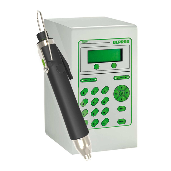
Hardware Description 6.1 Views of the AST11 6.1.1 Front Panel Display Function display Operating elements Figure 1: Front view AST11... -
Page 12: Rear View
6.1.2 Rear View Attachment points Filter openings Attachment points Figure 2: Rear view To ensure the air exchange, the filter openings must not be covered up. The inside filter can be replaced. -
Page 13: Connection Panel
GX10 for connection of: printer barcode scanner or fieldbus ethernet GX9 main switch fuse voltage supply GX2 F-Controller port GX7 feeder port GX8 emergency stop port GX11 (not shown, only by type AST11-1-S and AST11-2-S) screwdriver port GX1 I/O interface GX6... -
Page 14: Interface Description
6.2 Interface Description 6.2.1 Fuse Description: Main Fuse Size: Type: M2/250E, 20x5 mm Glasrohr 6.2.2 Voltage Supply Description: GX2 Connector: Hirschmann STASEI 200 Voltage: 230/115 V, 50/60 Hz 6.2.3 Ethernet Description: GX9 Connector: female connector RJ45 6.2.4 Screwdriver Description: GX1 Connector: SUB-D 15-pole (socket) 6.2.5 I/O Interface Description: GX6... -
Page 15: Multifunctional Serial Interface
Pin 21 internal 24 V 24 V (Emergency stop) Pin 23 Release controller/ emergency stop If a relay is used, when the sequence controller is switched on the signal 'Release control- ler / emergency stop' must have a delay of at least 1 second after switching on the 115/230V supply. -
Page 16: Feeder Port
Port adjustment when used with barcode scanner: • 9600 – 115200 baud selectable • 5 – 8 data bits selectable • 1 – 21 stop bits selectable • parity selectable • no protocol 6.2.7 Feeder Port Description: GX8 Connector: Binder Round-Connector Series 763, M12-4pole Color: black Description... -
Page 17: F-Controller Port
Description Used for: Contact Relay A1 (+24 V) Contact Relay A2 (GND) Contact Normally Closed Contact terminal 2 potential-free contact Contact Normally Closed Contact terminal 1 Table 4: Pin assignment emergency-stop 2 channel IMPORTANT The relay must only be switched on without any load! Pay attention to the signal sequence (see 7.6.2.5 Standard Communica- tion higher level controller –... -
Page 18: Commissioning
Commissioning 7.1 Dimension Sheet Figure 5: Dimension sheet... -
Page 19: Assembly Instructions
7.2 Assembly Instructions WARNING Risk of fatal injury due to electrocution! Switch off the AST11 sequence controller at the main switch and remove the mains plug before connecting the screwdriver! Commissioning should be done only by trained personnel. For the initial start-up proceed as indicated in the brief instructions 014090 "Quick-Start Instructions for the Operation of the Sequence Controller AST11 with 320E... - Page 20 Optional: Connect the plug of I/O-interface and screw on the retaining screw tightly. (to the GX6 interface) ATTENTION Sequence controller not function- ing! The interface GX6 must always be occupied. When the I/O interface is not in use plug in the connector 385476 A. Optional: Multifunctional serial printer to connect a printer, barcode scanner or fieldbus module, see...
- Page 21 Connect the sequence controller AST11 to the power supply (GX2 interface). Plug the power cable into the power socket. Switch on the sequence controller AST11 using the main switch. More information about the interface assignment can be found under 6.1.3 Connection panel 6.2 Interface Description Read the Operating Instruction /Safety Guidelines.
-
Page 22: Example For Screwdriving Systems
7.3 Example for screwdriving systems handheld screwdriver power supply cable AST11 Figure 6: Screwdriving system... -
Page 23: Minimum Bending Radius Of Screwdriver Cable
7.4 Minimum bending Radius of Screwdriver Cable ATTENTION Non-observance will cause damage to the screwdriver cable! Observe minimum bending radius of screwdriver cable. At constant motion: Minimum bending radius 90 mm At singular motion: Minimum bending radius 45 mm Please make sure that there is no mechanical load on the cables during operation. -
Page 24: Operation With A Stationary Screwdriver
7.6.2.2 Operation with a stationary Screwdriver The start signal starts screw assembly on spindle screwdrivers. The program indicated in the Setup "Type of program choice" menu is started. • When “Inputs” is selected and a program is entered via the inputs of the I/O interface then this program will be started (see 7.6.2.3 Selection and Start of a Screwdriving Program via I/O... -
Page 25: Standard Communication Higher Level Controller - Emergency Stop 2 Channel
With the program launch, the Ready signal and OK / not OK is set on low level. The follow- ing high-level of OK or not OK signals the end of screwdriving cycle. IMPORTANT The start signal must be at least 150 ms on LOW between two screw as- semblies. -
Page 26: Connection On A Master Controller Via The Fieldbus (Optional)
6. 100 ms after setting Emergency-Stop to high, the Program-Start can be set to high in order to start a new screwdriving cycle. ready O.K. / NOT O.K. Program start emergency stop normally closed contact Figure 8: Burst Burst-explanation: a) Complete screwdriving cycle b) Waiting-time between two screwdriving cycles c) New screwdriving cycle d) Emergency-Stop-Situation (Set and Reset) -
Page 27: Connection On A Master Controller Via The Fieldbus (Optional)
7.7 Connection on a master controller via the Fieldbus (optional) 7.7.1 Profibus DP / Profinet The device files for Profibus and Profinet may be downloaded via the web interface of the 8.3.4.17 Tools AST11 (see Fieldbus). 7.7.1.1 General Information All the program modules necessary for Profibus or Profinet connection to a Siemens S7 - controller are available in the DEPRAG_AST11PNDP.zip software package. -
Page 28: Software
7.7.1.2.2 Profinet Figure 10: Hardware configuration of Profinet 7.7.1.3 Software The following modules or UDT's are required to control the AST11 via the Profibus or Pro- finet: Module Name Description Control module for the AST11 sequence controller FB15 AST11 This module must be loaded for each AST11 sequence controller (with each new instance data block respectively) DB50 IDB_AST11DP... -
Page 29: Table 8: Directory Of The Modules
Table 8: Directory of the modules 7.7.1.3.1 Description - Interface parameters (FB15) Designation Type Data type Description Input address from the hardware configuration e.g. I_Addr1 Input address from the hardware configuration e.g. I_Addr2 Input address from the hardware configuration e.g. I_Addr3 Input address from the hardware configuration e.g. -
Page 30: Table 10: Description - Data Structure Of The Control Signals (Udt51)
7.7.1.3.2 Description - Data structure of the control signals (UDT51) Data Designation Description type Start signal for the AST11 When the state of the start signal changes from "low" to "high", the Start BOOL pre-selected screwdriving program is started on the AST11 – se- quence controller The start signal must be present until the screw- driver operation has ended. -
Page 31: Table 11: Description - Data Structure Of The Status Signals (Udt52)
7.7.1.3.3 Description - Data structure of the status signals (UDT52) Designation Data type Description System OK SystemOk BOOL This signal indicates that the AST11 – screwdriver controller has started up and is ready. Ready Ready BOOL This signal indicates that the AST11 – screwdriver controller is ready for screwdriver operation. -
Page 32: Table 12: Description - Error Codes
7.7.1.3.4 Description – Error Codes Error Description Error in the input address range Cause: FF00 The interface parameter I_AddrX (X=1-4) does not have a value or has one that is <= 0. Error while reading the input module 1 (I_Addr1) Possible causes: FF01 An incorrect input module has been entered in the hardware configuration. - Page 33 7.7.1.3.5 Description - Data structure of the screw data (UDT53) Designation Data type Description Program number fd_Prog The program number of the screwdriver program started previ- ously is output here. Screw status The screwdriver status is output here in detail. fd_Status (for possible values of the status, see 14.2 Error in the screwing...
-
Page 34: Table 13: Description - Data Structure Of The Screw Data (Udt33)
F-Function: Status Here the status of the last screw assembly of the AST11 started using F-Function is shown: Possible values: 0 = OK FC_STATUS 1 = too short 2 = too long 3 = part missing 4 = change part FC_COUNTER F-Function: Target screw assemblies _TARGET... - Page 35 7.7.1.3.6 Data backup The 'Save values' command can be used as often as desired in the screwdriver operation, but however, only the last three values are saved. In case of an error or a failure, the val- ues are always saved. The value last saved is always available in the range fd_Step3 / fd_Torque3 / fd_Angle3.
-
Page 36: Instructions For The Sequence Controller
Instructions for the Sequence Controller 8.1 General The sequence controller can be programmed by using the WEB-Interface or by the inte- grated numeric keypad, whereby the programming choices on the keypad are more lim- ited. The sequence controller can be operated as a stand-alone unit or it can be operated by a PLC. -
Page 37: Keypad Layout
8.2.2 Keypad Layout 8.2.2.1 Function Keys In automatic mode, the function keys have the following functions: left function key: manual reloading of a screw when operated with feeder right function key: part approval when using the F-Function, if this function has been en- abled in the relevant menu. -
Page 38: Menu Structure
8.2.3 Menu Structure System-Info Tool-Data System-Data Process-Data Screwdriver Programs Statistics Setup Date / Time Language Torque Unit Main Direction Startmode Handtool Opt. Parameters Password Device Addresses IP-Address Gateway Printer Options Torque Adjust- ment Display Contrast Start Release Speed Reduction Beeper Default Values Maintenance Interval F-Control... -
Page 39: Menu Functions
8.2.4 Menu Functions All sub-menus, where values can be changed or which causes the interruption of the au- tomatic operation, are protected by a password. If the password is set to 0000, then all menus are freely accessible! The password may be changed in the menu item SETUP. Important The following settings are implemented at delivery: Password: 0000... -
Page 40: Menu Setup
8.2.5.2.2 Statistics To use the statistics display, make sure to include the command STATISTICS in the screwdriver program. The data will not be saved permanently. When the AST11 is switched off, the data will be deleted. 8.2.5.2.2.1 Show First, input the program number to display the statistics. Then you can select between dis- play of torque or angle. - Page 41 8.2.5.3.2 Language The system allows the selection between different languages. Use the cursor keys to select the required language and confirm your selection with the ENTER-key. To leave the menu without making any changes, use the ESC-key. 8.2.5.3.3 Unit Several different measuring units are available. Use the function keys for selection and the ENTER key to accept the selection.
- Page 42 8.2.5.3.6.2 Device Addresses IP-Address: When the IP-Address is changed, the system starts-up new! To change the IP-Address: • use the function key “Modify?” • input the four numerical blocks individually • confirm your entry with the ENTER-key • input the four numerical blocks for the net mask •...
- Page 43 8.2.5.3.6.4 Torque Correction Factor (TQ-Adjustment) Use this area to input an individual value, which adapts the torque to an external meas- urement. ATTENTION When inputting a correction factor, the factory-made calibration will be changed. (The torque established by this factor is only valid for the torque, which was obtained by the input factor.) To change the value, proceed as follows: •...
- Page 44 8.2.5.3.6.9 Default Values Use this menu area to reset the setup-adjustments of the sequence controller to the origi- nal values (see 10.2 Default Values). 8.2.5.3.6.10 Maintenance Interval In this menu the maintenance intervals can be set (see also 10.1.1 Parameters of the Sys- Settings).
-
Page 45: Menu Screwdriving Sequence
8.2.5.4 Menu Screwdriving Sequence 8.2.5.4.1 Modify Use the menu item “Screwdriving Sequence Modify” to adjust the parameters of the in- dividual screwdriving program. At first, the system asks for the program number to be in- put. Thereafter, the cursor allows to select between the individual parameters within one program. -
Page 46: Menu Test
8.2.5.5 Menu Test 8.2.5.5.1 Tool Test 8.2.5.5.1.1 Speed Test The mode “speed test” allows the testing of the speed outside of the program sequence. The two function keys can control the speed test. Proceed as follows: • input nominal speed: •... - Page 47 8.2.5.5.1.4 Tool I/O Test (only visible with handheld Screwdrivers) Use the menu item “Tool I/O Test” to test the LED’s and buttons on the screwdriver. Use the cursor-keys to switch between the individual LED’s and buttons. The status of the button will be displayed; the LED’s may be turned on or off by the EN- TER-key.
- Page 48 8.2.5.5.4 Interface Test 8.2.5.5.4.1 I/O-Port Use the menu item I/O–Port to verify the I/O-conditions. Use the numerical keys 0 to 7 to activate or deactivate each individual output. Exit the I/O–Test mode with the ESC-key. Description of each step in the display: Inputs: 000000000000 Input 1:...
- Page 49 Use the ENTER-key to turn the individual LED’s on or off. To exit the LED-test menu at any time, simply press the ESC-key. 8.2.5.5.8 Special Tests These test functions are exclusively for internal use and only accessible to DEPRAG ser- vice personnel.
-
Page 50: Operation Via The Web Interface
8.3 Operation via the web interface 8.3.1 Requirements 8.3.1.1 Hardware The web interface operates on any common PC or Notebook with a network card or a WLAN card. 8.3.1.2 Software The web interface can be used with any common operating system, such as MS Windows, Linux, OS X... -
Page 51: Menu Structure
8.3.3 Menu Structure The menu has the following structure: Start Page System Info Tool Data System Data Process Data Screwdriving Sequence Statistics Graphic Final Values Setup General Settings Time F-Control New Password Serial Device Extensions Screwdriving Sequence Tools Manuals Additional Programs Fieldbus Update Figure 13:... -
Page 52: Description Of The Menu
8.3.4 Description of the menu 8.3.4.1 Start To access the web interface, enter the IP address of the sequence controller AST11 (also refer to 8.2.5.3.6.2 Device Addresses) into the address bar of the browser and press the enter key (e.g. "http://10.10.25.108"). The browser connects to the sequence controller AST11 and loads the home page. -
Page 53: System Info Tool Data
If you enter a valid password then all pages are accessible. Otherwise, the pages on which changes can be made are hidden. System Info Tool Data 8.3.4.2 This page displays the most-important data of the connected Screwdriver. These data cannot be changed on this page. -
Page 54: System Info System Data
System Info System Data 8.3.4.3 This page shows the screwdriver independent adjustments of the sequence controller. These data cannot be changed on this page. Figure 17: System data The following data is displayed: • Version of main unit: software version of the main unit •... -
Page 55: Process Data Screwdriving Sequences
Figure 18: System data, lower part of the page • Print options o values of O.K. and NOT O.K. assemblies o only values of O.K. assemblies o only values of NOT O.K. assemblies • Offset gear: If the screwdriver is equipped with an external ancillary transmission, this area indicates the corresponding values for the offset gearing;... -
Page 56: Process Data Statistics
Figure 19: Screwdriving program This page does not allow generating or changing screwdriving sequences. There are ma- ximum 16 individual screwdriver sequences. Available programs are gray highlighted; the buttons for other programs remain white. Figure 20: Screwdriving program with displayed parameter values Process Data ... -
Page 57: Process Data Graphic
Figure 21: Statistics Click on “Refresh data”, if further screw assemblies have been carried out whilst the statis- tics page has been open. In the lower half of the page the statistics data and the limit values of all programs can be deleted. -
Page 58: Process Data Final Values
The following data are recorded: • speed • torque • angle • program step • current • screwdriver temperature Process Data Final Values 8.3.4.7 This page offers the possibility to save the final values of all assemblies of the last seven days as csv-values (refer to 12.1 Final values). -
Page 59: Setup General Settings
Setup General Settings 8.3.4.8 Here it is possible to perform most settings for the sequence controller AST11. Figure 24: General settings A description of the individual parameters can be found in Chapter Settings. Click "Submit" to transfer the settings to the sequence controller AST11. Click "Default Values"... -
Page 60: Setup Time
Setup Time 8.3.4.9 Here, you can enter the date and time of the sequence controller AST11. Figure 26: Date / Time Setup F-Control 8.3.4.10 If you use the F-control function, use this area to do the appropriate adjustments. Figure 27: Setup F-Control More information on the F-Control function you find in chapter... -
Page 61: Setup Serial Device
Setup Serial Device 8.3.4.12 On this page you can set which device is connected to the multi-functional serial interface. If there is no device connected, select “no device”. 8.3.4.12.1 Printer Figure 29: Printer settings The following settings can be altered: •... -
Page 62: Figure 31: Settings For Fieldbus, Ethercat Example
Figure 31: Settings for fieldbus, EtherCAT example Figure 32: Settings for fieldbus, EtherNet/IP example Figure 33: Settings for fieldbus, Profibus example Figure 34: Settings for fieldbus, ProfiNet example Click on “Submit”, to transfer the settings to the AST11. -
Page 63: Figure 35: Settings For Program Selection Via Barcode
8.3.4.12.3 Barcode-Scanner If a barcode scanner is connected to the sequence controller via the serial interface then the relevant settings can be carried out here. Details can be found in the instruction man- ual of your barcode scanner. Figure 35: Settings for Program selection via barcode The following settings can be altered: •... -
Page 64: Setup Extensions
Different options are available, at extra cost, for the sequence controller AST11 (also refer 17.10 Optional software packages). To activate these options please contact the DEPRAG sales department or your DEPRAG dealer. In order to be able to perform the activation, some information is required which must be contained in your order: ◦... -
Page 65: Figure 37: Screwdriving Sequence - Empty Program
Figure 37: Screwdriving sequence – empty program If there is no program a standard program can be created. Select the type of program and then it will be created by the sequence controller AST11. For a detailed description of the screwdriving strategies and commands 11 Screwdriving Strategies and Commands. -
Page 66: Figure 38: Screwdriving Sequence
Select an available program step by clicking this step. Subsequently click the strategy or the command that you like to insert. If you click "insert before", the strategy or command should be inserted in front of the currently selected program step or click "insert after", if the strategy or the command should be inserted behind the currently selected program step. - Page 67 IMPORTANT A program step, a complete program or all programs are deleted immedi- ately without a confirmation prompt Create / Load backup: At the lower part of the page you may • back up existing programs • saved programs can be restored and •...
-
Page 68: Tools Manuals
Tools Manuals 8.3.4.15 On this page you can transfer and read all available manuals for the sequence controller AST11. If your browser has a pdf plug in, then you can read the manuals directly in the browser. Figure 39: Manuals Tools ... -
Page 69: Tools Fieldbus
Tools Fieldbus 8.3.4.17 On this page, you may download all fieldbus drivers available for the AST11 sequence controller. Figure 41: Fieldbus Tools Update 8.3.4.18 New software can be loaded onto the sequence controller in the Update menu (also see 13.1 Updating the software). -
Page 70: Function
F-Function 9.1 General The F-function of the AST11 offers – besides the supervised values of torque and angle – the following additional possibilities: • Supervision of total duration of an assembly and with this option it is possible to de- tect incorrect screw threads, missing washers or an indirect depth control. -
Page 71: Operation With Supervision Of Number Of Screw-Joints Per Part
• If a part-presence sensor is used: Presence of the part The following additional errors or informational notes are shown: Error Displayed Text Meaning Number no error TOO SHORT the predetermined minimum time of the screw-process was not reached TOO LONG the predetermined maximum time of the screw-process was exceeded PART MISSING... -
Page 72: Menu Functions For The F-Function
9.3 Menu Functions for the F-Function 9.3.1 Settings 9.3.1.1 Activate The system offers a choice between „Activate F-Function“ yes or no. Make your selection with the cursor keys. Confirm your selection with the ENTER-key and exit this menu with the ESC-key. 9.3.1.2 Reset Button The system offers a choice between „Reset by Button“... -
Page 73: Diagnostic Functions
9.3.1.4.2 Time Frame The time frame for the screw-joint may be changed. To change the value, proceed as follows: • Use the left function key „Modify?“ • input the value for the minimum cycle time and confirm the input with the ENTER-key •... -
Page 74: Settings
10 Settings 10.1 Description of the adjustable parameters 10.1.1 Parameters of the System Settings Parameter Description IP Address The IP address via which the AST11 can be reached in the network. Network mask It indicates the network segment in which the se- quence controller AST11 is located. - Page 75 Maintenance interval The maintenance interval determines after how many screwdriving procedures the screwdriver should be checked/undergo maintenance. If a maintenance interval is entered then the se- quence controller AST11 signals that the next main- tenance of the EC screwdriver is due. This message can be acknowledged by pressing the ESC key and work can continue as normal.
-
Page 76: Special Parameters For Fieldbus Systems (Optional)
F-Control active Indicates whether F-control is active. Reset by Button If there is an error in screw assembly the reset button can be pressed. Release by Button Once screw assembly on a part is finished this button releases the part. Number of Cycles Number of screw assemblies per component Minimum Time... -
Page 77: Default Values
10.2 Default Values 10.2.1 System Settings The default values can be adjusted as follows: • in the menu System Opt. Parameters Default Values at the control, press the left function key • click the "Default Values" button in the web interface in the Settings menu General Settings. -
Page 78: Table 24: Default Values For Ethernet Ip
Ethernet IP: Parameter Value IP address 10.10.24.11 Net mask 255.255.0.0 Gateway 10.10.20.9 DHCP inactive BOOTP inactive Table 24: Default values for Ethernet IP Ethercat: No settings are necessary. -
Page 79: Screwdriving Strategies And Commands
11 Screwdriving Strategies and Commands 11.1 Screwdriving Strategies 11.1.1 Fasten / Loosen to Torque The screwdriving strategy fasten / loosen to torque is a tightening / loosening process with stop control via parameter torque. Angle monitoring is possible as an option. Strategy Description: Figure 43: Screwdriving Application to torque Strategy description:... -
Page 80: Extended Fasten To Torque
Parameters: The following parameters are used in the screwdriving Sequence: • Supervision time: maximum time until the cut-out torque is reached • Shut-off torque, shut-off torque upper/lower limits • Speed • Torque holding time • Angle supervision: active / inactive if angle monitoring is active the following parameters are added: ◦... -
Page 81: Fasten / Loosen To Angle
Analysis: OK evaluation: The screwdriving sequence is considered OK (fault free), if the shut-off occurs via tor- que and the torque value is within the preset limits. If the Angle monitoring option is active the final angle value must be within the preset limits. -
Page 82: Figure 46: Loosening On Angle
Figure 46: Loosening on Angle Strategy Description: At the start of the screwdriving sequence time monitoring and angle measurement is started. Cyclic torque measurements are performed. Shut-off criteria: The screwdriving process is ended once the • shut-off angle is achieved •... -
Page 83: Fasten / Loosen To External Stop-Signal
11.1.4 Fasten / Loosen to external Stop-Signal The screwdriving strategy Fasten/Loosen to External Stop-Signal is a screwdriving proc- ess with switch off to external signal. Figure 47: Fasten / Loosen to external Stop-Signal Sequence of the Screwdriving Strategy: • at the start of the screwdriving start of the screwdriver with pre-selected speed and time monitoring •... -
Page 84: Friction Value Package (Optional)
11.1.5 Friction value package (optional) 11.1.5.1 Friction value measurement The function of the screwing sample is the tightening of a screw, while considering the fric- tion value prior to the head connecting to the surface. Sequence of the screwing sample Figure 48: Friction value measurement Switching off criteria: The measuring process is ended once the... -
Page 85: Fasten To Differential Torque
Parameter: The following parameters are used in the screwing sample: • Supervision time Maximum time until the screwing level is aborted • Angle friction measurement Input of the angle range in which the friction monitoring should be active. • Friction value type: Mean value/maximum value selectively the maximum value or mean value of the friction value can be used to de- termine the friction torque. - Page 86 Switching off criteria: The screwing process is ended once the • cut-out torque is reached • a monitoring criteria is reached • the maximum screwing time (monitoring time) is expired Analysis: OK evaluation: The screwing level is considered OK (fault free), if the switching off occurs via the differential moment and the value of the torque is in the set limits.
-
Page 87: Fasten Dependent On Friction Value
• Angle supervision: active / inactive Monitoring of the angle with a window angle if the angle monitoring is switched on, the following parameters are added: ◦ Threshold torque Input of the torque from when the angle monitoring should be started (compare point 1 in the previous figure). - Page 88 Analysis: OK evaluation: The screwing level is considered OK (fault free), if the switching off occurs via the differential moment and the value of the torque is in the set limits. On the angle of rotation monitoring option the reached angle must be within the set limits.
- Page 89 • Differential torque lower limit Lower limit of the differential end moment. The actual torque lower limit results from the sum of the lower limit of the friction moment and the lower limit of the differential moment. • Differential torque upper limit Upper limit of the differential end moment.
-
Page 90: Commands
11.2 Commands 11.2.1 Display values Displays the values of the previous screwing level at the touch display. The command can used as often as you like. 11.2.2 Save values Saves the values of the previous screwing level into the end value data set. The command can be used as often as you like (also see 8.3.4.7 Process Data ... -
Page 91: Wait For Input
11.2.7 Wait for input Waits for an input signal. Only available for input number 2. Change to the next step will occur as soon as the input is set. Parameters: • maximum waiting time • Input number 11.2.8 Set output Sets an output. -
Page 92: Documentation
12 Documentation The sequence controller AST11 provides a wide variety of documentation possibilities. 12.1 Final values If the command 'save value' is used on the screwing program, then the screwing results are stored in a CSV data and can be loaded by the sequence controller via the web inter- 8.3.4.7 Process Data ... -
Page 93: Curve Representation
12.2 Curve Representation A screwdriving curve is created for every screwdriving process with the AST sequence controller. This can be viewed or saved in different ways. • Displayed directly on the control unit in the Process Data menu area Graphic •... -
Page 94: Statistic
12.3 Statistic If the command "statistic" is used in the screwing program then in the sequence controller AST11 a statistic is kept about the last 100 values for the respective program. The following values are calculated for moment and angle: •... -
Page 95: Table 26: Print Parameters
screwdriver Screwdriver type Value 311E27-0020 calibration Calibration value Value 1,000 Statistics Angle Mean StatAngleAv Value unit 1081 ° Value Statistics Angle Stan- StatAngleStddev% Value unit 1.36 % dard Deviation % Statistics Angle Stan- StatAngleStddevAbs dard Deviation Abso- Value unit 14.70 lute StatAngleCPK Statistics Angle CPK... - Page 96 At the time of delivery the standard format is: @date_iso @time PG: @prog ST: @step TQ: @torque AN: @angle @errortext Issue: 2013-04-24 07:13:37 PG: 12 ST: 3 TQ: 2.15 Nm AN: 1080 ° The amended format string @date_euro @time Program: @prog step: @step fault: @error runtime:@runtime torque: @torque angle: @angle delivers following output, e.g.: 24.01.2013 07:13:37 Program: Step 12: 3 faults 0 runtime: 0.5 s torque: 2.15 Nm angle:...
-
Page 97: Maintenance And Servicing
13 Maintenance and servicing Incorrect disassemb ly or assembly can lead to injury of an operator and damage of the ma- chine. Disassembly and assemb ly work may only be carried o ut by DEPRAG or qualifi ed personnel . -
Page 98: Updating The Software
13.1 Updating the software 13.1.1 Main control and touch display Updating can only be done via the web interface. Registration is done as described in sec- tion 8.3.4.1 Start. Click on Tools >> and then Update. In order to update the main control, enter the file name and path in the input field and click "load". -
Page 99: Figure 51: Power Unit On The Rear Housing Wall
This is how you replace the filter mat: 1. Prior to opening the housing, the sequence controller must be switched off and the power plug must be disconnected and secured against unauthorized plugging in. 2. Loosen the six screws (hexagon socket wrench SW 2.5) at the housing rear wall. 3. -
Page 100: Spare Parts
Caution Prior to the re-start perform the operating media test acc. to the valid regulations, e.g. BGV A3. 13.3 Spare parts Designation Part no. Filter mat 826057... -
Page 101: Error Display And Troubleshooting
Number Meaning Trouble shooting Switch the AST11 off and then restart again. If Power unit not found the fault remains, please contact the DEPRAG Service Department. Position indicator index signal not found Ensure that the drive unit of the EC-screwdriver turns freely. Re-start the QEP position indicator signal missing AST11. -
Page 102: Main Controller
Screwdriver and power unit do not Ensure that you have installed the correct match! screwdriver model to the AST11. The AST11-1/-S can be operated with screw- drivers of the series 320Exx19 and 320Exx22 and 320Exx27. The AST11-2/-S can be operated with screw- drivers of the series 320Exx36. -
Page 103: Communication
14.1.4 Communication Number Meaning Trouble shooting No connection General error Checksum error Module not found Switch the AST11 off and then restart again. Unknown command Timeout Access to write-protected area Value outside of limits! Table 30: System error – Communication 14.2 Error in the screwing sequence Number Displayed text... -
Page 104: Table 31: Fault In The Screwing Sequence
Check the screw process and Overload of the tool via a de- adapt if required. If necessary IIT-ERROR fined time frame please contact DEPRAG Ser- vice. Specify a program number PG NUM > 15 The program number is invalid. between 1 – 15. -
Page 105: Trouble Shooting
Check the Program Choice selection in Menu Setup >> Ba- does not start sic Settings. Table 32: Troubleshooting If you detected that the sequence controller AST11 is defective, then send it to DEPRAG. Under no circumstances should you try to find or remedy the electrical fault. -
Page 106: Required Accessories
16 Required accessories All catalogs are available for download from our web site: www.deprag.com 16.1 Power Cable Designation Part no. Power cable KN AST11-EU – 1.8m / 5.9 ft. 385443 A Power cable KN AST11-US – 1.8m / 5.9 ft. -
Page 107: Fieldbus Modules
17.4 Fieldbus modules Only one module can be used per sequence controller. The fieldbus module cannot be used in conjunction with the printer or with the barcode scanner. Figure 53: Fieldbus module, power supply and connection cable 17.4.1 Profibus Designation Part no. -
Page 108: Toolbox
The printer cannot be used in conjunction with the barcode scanner or with the fieldbus module. Designation Part no. ND100 printer 823476 Connection cable 349938 A 17.9 Hardware-Module Only for type AST11-1 and AST11-2. Safe stop without rebooting system Designation Part no. 385521 A EMERGENCY-STOP-Module... - Page 109 Example slide door:...
-
Page 110: Optional Software Packages
17.10 Optional software packages 17.10.1 Friction value software package The software package friction values contain the following additional screwing samples: • Friction value measurement • Screwing on differential torque • Screwing applications depending on friction For detailed description also refer to 11.1.5 Friction value package (optional). -
Page 111: Graph10 - Superimposed Graph Display
17.10.2 GRAPH10 – Superimposed graph display Figure 54: GRAPH10E The GRAPH10(E) program can be downloaded free of charge via the web interface. How- ever, the use of the superimposed graph display feature is subject to cost. Designation Product–Code Graph 10E Enabling superimposed graph display 202698... -
Page 112: Datalogger
(AST) or ComCenter 10 and to archive them. The DataLogger program can be downloaded free of charge via the web interface. How- ever, the use of the program is subject to cost. Designation Part no. DEPRAG Datalogger release key 202699... -
Page 113: Tc30-Pc Statistics
Figure 56: TC30-PC Statistics TC30-PC Statistics is a statistics programme for use in combination with DEPRAG- DataLogger. This software is for evaluation of the screwdriving data and calculation of av- erage value, standard deviation and cmk value. For the graphic display several alterna- tives may be selected. -
Page 114: Deprag Astxx Serial Remote
17.10.5 DEPRAG ASTxx Serial Remote Figure 57: DEPRAG ASTxx Serial Remote The ASTxx Serial Remote provides the possibility to save screwdriving graphs and end value data sets from a sequence controller to a computer. The supervision, when and which data should be saved, is done by a PLC. -
Page 115: Technical Data
18 Technical Data Type AST11-1 AST11-2 Part-no. 390041 A 390042 A Type AST11-1-S AST11-2-S Part-no. 390041 B 390042 B Voltage 100-240 VAC / 50 (60) Hz Cycle 250 W (max) 400 W (max) Power consumption 100 mA Maximum load per outlet 100 mA Total current max. -
Page 116: Glossary
19 Glossary Term Description Clearance for start If the clearance for start is activated then the screwdriver will only start if there are 24V at the clearance to start input. Oth- erwise the controller is not ready to screw. Command General program step to create the screwdriving sequence (e.g. - Page 117 see main controller n.c. not connected – the named pin is not connected not error free error free Power unit Component for the motor control of the screwdriver Process ability index (C = total specific torque tolerance of the Connection: 6 Sigma (s). This index just provides information about the spread angle of the torque values.
- Page 118 tolerances. The required documentation for this can only be provided under point a) found legality. The verification of the process ability must be done over a longer time period. Random sampling is done in set intervals from the running process and quality characteristics are re- corded (measured).
- Page 119 Stationary screwdriver Screwdriver for stationary use Switching off criteria Criteria to which the screw assembly should be done (e.g. torque, angle etc.). Accessories for the automatic selection of a certain screwdriv- Toolbox ing program based on the used tool. Web interface Software interface for the programming of the sequence con- troller that are actuated via a standard Internet browser.
-
Page 120: Eg-Conformity Declaration
the relevant technical documentation in accordance with part B of ANNEX VII will be transmitted in re- sponse to a reasonable request by the national authorities in printed form or electronic form (pdf) Manufacturer and authorized Person for Documentation: DEPRAG SCHULZ GMBH U. CO. P.O. BOX 1352, GERMANY-92203 AMBERG CARL-SCHULZ-PLATZ 1, GERMANY-92224 AMBERG... -
Page 121: Service Locations And Authorized Partners
If you need any further information then please either contact your representative or us directly at DEPRAG SCHULZ GMBH u. CO. During business hours our Service-Hotline + 49 (0) 700 00 371-371 is available for German and English speakers. - Page 122 DEPRAG SCHULZ GMBH u. CO. P.O. Box 1352, 92203 Amberg, Germany Carl-Schulz-Platz 1, 92224 Amberg, Germany Service Hotline +49 (0) 0700 00 371-371 +49 (0) 9621 371-0 Fax: +49 (0) 9621 371-120 Internet: http://www.deprag.com e-mail: info@deprag.de...
Need help?
Do you have a question about the AST11-1 and is the answer not in the manual?
Questions and answers