Sign In
Upload
Manuals
Brands
Deprag Manuals
Controller
AST11-2-S
Deprag AST11-2-S Manuals
Manuals and User Guides for Deprag AST11-2-S. We have
1
Deprag AST11-2-S manual available for free PDF download: Operating Instruction Booklet
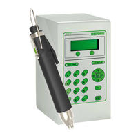
Deprag AST11-2-S Operating Instruction Booklet (122 pages)
Sequence controller
Brand:
Deprag
| Category:
Controller
| Size: 2.95 MB
Table of Contents
Table of Contents
2
1 Definition of Signal Words and Symbols
8
2 Safety Instructions
9
3 Intended Use
9
4 Scope of Delivery
10
5 Short Description
10
6 Hardware Description
11
Views of the AST11
11
Front Panel
11
Figure 1: Front View AST11
11
Rear View
12
Figure 2: Rear View
12
Connection Panel
13
Figure 3: Connection Panel AST11-1
13
Interface Description
14
Fuse
14
Voltage Supply
14
Ethernet
14
Screwdriver
14
I/O Interface
14
Table 1: Pin Assignment I/O Interface
14
Multifunctional Serial Interface
15
Table 2: Pin Assignment Multifunctional Serial Interface
15
Feeder Port
16
Emergency-Stop 2 Channel
16
Figure 4: Connection of Feeder Port
16
Table 3: Pin Assignment Feeder Port
16
F-Controller Port
17
Table 4: Pin Assignment Emergency-Stop 2 Channel
17
Table 5: Pin Assignment F-Controller
17
7 Commissioning
18
Dimension Sheet
18
Figure 5: Dimension Sheet
18
Assembly Instructions
19
Example for Screwdriving Systems
22
Figure 6: Screwdriving System
22
Minimum Bending Radius of Screwdriver Cable
23
Information on Programming the Sequence Controller
23
Functioning of the Sequence Controller AST11
23
Operation as Stand-Alone Unit with a Handheld Screwdriver
23
Operation with a Higher Level Controller
23
Operation with a Handheld Screwdriver
23
Operation with a Stationary Screwdriver
24
Selection and Start of a Screwdriving Program Via I/O Interface
24
Standard Communication Higher Level Controller - AST11
24
Table 6: Program Choice
24
Standard Communication Higher Level Controller - Emergency Stop 2 Channel
25
Figure 7: Burst
25
Connection on a Master Controller Via the Fieldbus (Optional)
26
Profibus DP / Profinet
26
General Information
26
Figure 8: Burst
26
Connection on a Master Controller Via the Fieldbus (Optional)
27
Profibus DP / Profinet
27
General Information
27
Hardware Configuration
27
Figure 9: Hardware Configuration of Profibus DP
27
Software
28
Figure 10: Hardware Configuration of Profinet
28
Table 7: Modules and Udt's for the Control
28
Table 8: Directory of the Modules
29
Table 9: Description - Interface Parameters (FB15)
29
Table 10: Description - Data Structure of the Control Signals (UDT51)
30
Table 11: Description - Data Structure of the Status Signals (UDT52)
31
Table 12: Description - Error Codes
32
Table 13: Description - Data Structure of the Screw Data (UDT33)
34
8 Instructions for the Sequence Controller
36
General
36
Operating Elements
36
Functional Display (Leds)
36
Figure 11: Operating Elements
36
Table 14: Leds
36
Keypad Layout
37
Function Keys
37
Numerical Keypad and ESC-Key
37
Menu and Cursor Keys
37
Table 15: Menu and Cursor Keys
37
Menu Structure
38
Figure 12: Menu Structure at the Display
38
Menu Functions
39
Description of the Menus
39
Menu System Info
39
Menu Process Data
39
Menu Setup
40
Menu Screwdriving Sequence
45
Menu Test
46
Operation Via the Web Interface
50
Requirements
50
Hardware
50
Software
50
Connection to the Sequence Controller AST11
50
Preparing to Use the Web Interface
50
Setting the Sequence Controller AST11
50
Setting the Browsers/Operating Systems
50
Menu Structure
51
Figure 13: Menu Structure Web Interface
51
Description of the Menu
52
Start
52
Figure 14: the Home Page
52
Figure 15: Start Page
52
System Info Tool Data
53
Figure 16: Tool Data
53
System Info System Data
54
Figure 17: System Data
54
Process Data Screwdriving Sequences
55
Figure 18: System Data, Lower Part of the Page
55
Process Data Statistics
56
Figure 19: Screwdriving Program
56
Figure 20: Screwdriving Program with Displayed Parameter Values
56
Process Data Graphic
57
Figure 21: Statistics
57
Figure 22: Downloading Curve Data
57
Process Data Final Values
58
Figure 23: Screwdriver Results
58
Setup General Settings
59
Figure 24: General Settings
59
Figure 25: General Settings - Lower Part of the Page
59
Setup Time
60
Setup F-Control
60
Setup Password
60
Figure 26: Date / Time
60
Figure 27: Setup F-Control
60
Figure 28: Change Password
60
Setup Serial Device
61
Figure 29: Printer Settings
61
Figure 30: Selection of Fieldbus
61
Figure 31: Settings for Fieldbus, Ethercat Example
62
Figure 32: Settings for Fieldbus, Ethernet/Ip Example
62
Figure 33: Settings for Fieldbus, Profibus Example
62
Figure 34: Settings for Fieldbus, Profinet Example
62
Figure 35: Settings for Program Selection Via Barcode
63
Setup Extensions
64
Screwdriving Sequence
64
Figure 36: Activating Options
64
Figure 37: Screwdriving Sequence - Empty Program
65
Figure 38: Screwdriving Sequence
66
Tools Manuals
68
Tools Additional Programs
68
Figure 39: Manuals
68
Figure 40: Additional Programs
68
Tools Fieldbus
69
Tools Update
69
Figure 41: Fieldbus
69
Figure 42: Update
69
9 Function
70
General
70
Functionality
70
Operation with Supervision of Number of Screw-Joints Per Part
71
Operation Without the Supervision of Number of Screw-Joints Per Part
71
Table 16: Errors of F-Function
71
Menu Functions for the F-Function
72
Settings
72
Activate
72
Reset Button
72
Part Clearance
72
Programs
72
Diagnostic Functions
73
Interfaces
73
10 Settings
74
Description of the Adjustable Parameters
74
Parameters of the System Settings
74
Special Parameters for Fieldbus Systems (Optional)
76
Profibus
76
Profinet
76
Ethernet IP
76
Ethercat
76
Table 17: Adjustable Parameters
76
Table 18: Configurable Profibus Parameters
76
Table 19: Configurable Profinet Parameters
76
Table 20: Configurable Ethernet IP Parameters
76
Default Values
77
System Settings
77
Special Parameters for Fieldbus Systems (Optional)
77
Table 21: Default Values
77
Table 22: Default Values for Profibus
77
Table 23: Default Values for Profinet
77
Table 24: Default Values for Ethernet IP
78
11 Screwdriving Strategies and Commands
79
Screwdriving Strategies
79
Fasten / Loosen to Torque
79
Figure 43: Screwdriving Application to Torque
79
Extended Fasten to Torque
80
Figure 44: Expanded Screwdriving to Torque
80
Fasten / Loosen to Angle
81
Figure 45: Screwdriving to Angle
81
Figure 46: Loosening on Angle
82
Fasten / Loosen to External Stop-Signal
83
Figure 47: Fasten / Loosen to External Stop-Signal
83
Friction Value Package (Optional)
84
Friction Value Measurement
84
Figure 48: Friction Value Measurement
84
Fasten to Differential Torque
85
Figure 49: Screwing on Differential Torque
85
Fasten Dependent on Friction Value
87
Figure 50: Screwing Applications Depending on Friction
87
Commands
90
Display Values
90
Save Values
90
Statistic
90
Print
90
Waiting Time
90
Hold Position
90
Wait for Input
91
Set Output
91
Reset Output
91
12 Documentation
92
Final Values
92
Table 25: Structure of the Data Set
92
Curve Representation
93
Statistic
94
Print Output
94
Table 26: Print Parameters
95
13 Maintenance and Servicing
97
Updating the Software
98
Main Control and Touch Display
98
Power Element
98
Replace the Filter Mat of the Sequence Controller
98
Figure 51: Power Unit on the Rear Housing Wall
99
Figure 52: Filter Mat on the Housing Rear Wall
99
Spare Parts
100
14 Error Display and Troubleshooting
101
System Error
101
MINIMAT-EC-Servo Screwdriver
101
Power Unit
101
Table 27: System Error MINIMAT-EC-Servo Screwdriver
101
Main Controller
102
Table 28: System Error - Power Unit
102
Table 29: System Error - Master Control Unit
102
Communication
103
Error in the Screwing Sequence
103
Table 30: System Error - Communication
103
Table 31: Fault in the Screwing Sequence
104
15 Trouble Shooting
105
Table 32: Troubleshooting
105
16 Required Accessories
106
Power Cable
106
17 Optional Equipment
106
Motor Cable for MICROMAT®-E
106
Extension for MICROMAT-E Motor Cable
106
Plug
106
Fieldbus Modules
107
Profibus
107
Profinet
107
Ethercat
107
Ethernet/Ip
107
Figure 53: Fieldbus Module, Power Supply and Connection Cable
107
Toolbox
108
Standfuß
108
Barcode Scanners
108
Printer Connector
108
Hardware-Module
108
Optional Software Packages
110
Friction Value Software Package
110
GRAPH10 - Superimposed Graph Display
111
Figure 54: GRAPH10E
111
Datalogger
112
Figure 55: Datalogger
112
TC30-PC Statistics
113
Figure 56: TC30-PC Statistics
113
DEPRAG Astxx Serial Remote
114
Figure 57: DEPRAG Astxx Serial Remote
114
18 Technical Data
115
Table 33: Technical Data
115
19 Glossary
116
20 Eg-Conformity Declaration
120
21 Service Locations and Authorized Partners
121
Advertisement
Advertisement
Related Products
Deprag AST11-1
Deprag AST11-1-S
Deprag AST11-2
Deprag AST40-1
Deprag AST6
Deprag 428001 A
Deprag SZG Controller 6
Deprag Categories
Power Screwdriver
Controller
Measuring Instruments
Drill
Power Tool
More Deprag Manuals
Login
Sign In
OR
Sign in with Facebook
Sign in with Google
Upload manual
Upload from disk
Upload from URL