Table of Contents
Advertisement
Quick Links
013735en
NOTICE ALL DOCUMENTATIONS !
Before beginning work this operating instruction booklet and the enclosed
safety instructions (no. 016000, pink-colored booklet) have to be read through
carefully. Always follow the instructions during operation. Give this operating in-
struction booklet and the appropriate safety instructions to the operator.
Operating Instruction Booklet
- Translation of the original instruction -
Sequence Controller
AST6
428001 A
Advertisement
Table of Contents
Troubleshooting

Related Manuals for Deprag AST6


Summary of Contents for Deprag AST6
- Page 1 013735en Operating Instruction Booklet - Translation of the original instruction - Sequence Controller AST6 428001 A NOTICE ALL DOCUMENTATIONS ! Before beginning work this operating instruction booklet and the enclosed safety instructions (no. 016000, pink-colored booklet) have to be read through carefully.
-
Page 2: Table Of Contents
Interface Fieldbus (optional)....................11 COMMISSIONING ........................12 Dimension Sheet........................12 Assembly Instruction ......................13 Information on programming the Sequence Controller ............14 Functioning of the Sequence Controller AST6............... 14 Connection to a master controller ..................15 7.5.1 I/O Interface ........................15 7.5.2 Fieldbus modules (optional) .................... - Page 3 Error in the Screwing Sequence ..................75 14.2 TROUBLE SHOOTING......................76 REQUIRED ACCESSORIES ....................77 Power Cable ........................77 16.1 OPTIONAL EQUIPMENT ....................... 77 AST6 to PC connecting Cable ..................... 77 17.1 Fieldbus Module........................77 17.2 17.2.1 Profibus ..........................77 17.2.2 Profinet..........................
- Page 4 SERVICE LOCATIONS AND AUTHORIZED PARTNERS ............ 88 List of figures Figure 1: Front Panel of AST6 ....................... 9 Figure 2: Connection Panel of AST6....................9 Figure 3: Dimension Sheet......................12 Figure 4: Main Screen: Process Display ..................14 Figure 5: Hardware configuration of Profibus DP.................
- Page 5 List of tables Table 1: Modules and UDT's for the control................. 17 Table 2: Directory of the modules ....................17 Table 3: Description - Interface parameters (FB13)..............18 Table 4: Description – Data structure of the control signals (UDT31).......... 19 Table 5: Description –...
-
Page 6: Definition Of Signal Words And Symbols
Definition of Signal Words and Symbols The signal words and symbols used in the technical documentation (safety instructions, operating instruction booklet, etc.) have the following meaning: DANGER Indicates an immediate danger which causes serious injuries or even death if not avoided. WARNING Indicates a threatening danger which can cause serious injuries or even death if not avoided. -
Page 7: Safety Instructions
Use beyond its intended use is considered unauthorized and therefore improper. Furthermore, DEPRAG is not liable for damage resulting from the misuse of the instrument; the user alone is liable. The correct use of the instrument includes compliance with all operating, maintenance and repair instructions. -
Page 8: Scope Of Delivery
320E12 and 320E19. It has a E/A interface and an Ethernet connection and as well as optional via one fieldbus interface. The sequence controller AST6 can be operated via the web interface as well as via the touch display. The web interface and the display on the touch display are available in several languages to select from. -
Page 9: Hardware Description
6.1.1 Front Panel Figure 1: Front Panel of AST6 6.1.2 Connection Panel Main switch GX4: Screwdriver connection GX1: Power supply connection (voltage supply) GX3: Ethernet GX2: SFD connection / clearance to start GX5 interface fieldbus (optional) Figure 2: Connection Panel of AST6... -
Page 10: Interface Description
Interface Description 6.2.1 Screwdriver Designation: GX4 Plug connector: SUB-D 15-pole (bushing) 6.2.2 Voltage Supply Designation: GX1 Plug connector: Circular plug-in connector 3-pole Also see Required Accessories Designation n.c. 6.2.3 Ethernet Designation: GX3 Plug connector: Bushing RJ45... -
Page 11: Input/Output Interface
6.2.4.2 Power Supply The I/O module (or component group) of the AST6 must be fed with 24V DC to use the inputs / outputs. This is done by feeding 24V DC via the pins 23 and 25. 6.2.5 Interface Fieldbus (optional) 6.2.5.1... -
Page 12: Commissioning
Commissioning Dimension Sheet Figure 3: Dimension Sheet... -
Page 13: Assembly Instruction
Assembly Instruction WARNING Risk of fatal injury due to electrocution! Put off the AST6 sequence controller at the main switch and remove the mains plug before connecting the screwdriver! Commissioning should be done only by competent personnel. For the initial start-up proceed as indicated in the brief instructions 013738 "Quick-Start Instructions for the Operation of the Sequence Controller AST6 with 320E... -
Page 14: Information On Programming The Sequence Controller
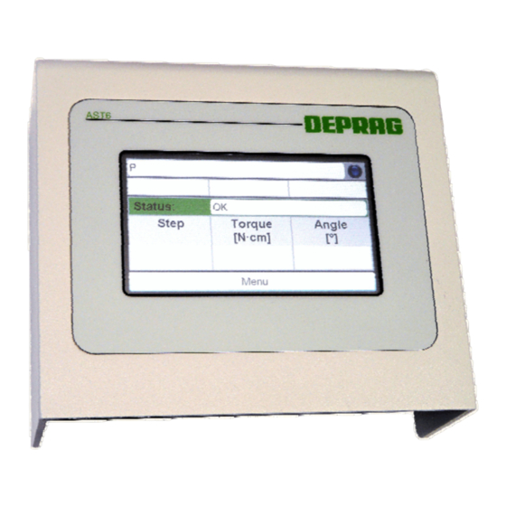
Applying the start signal initiates the screwing in operation. The program specified via the program selection is started. After switching on the sequence controller AST6 the main screen will appear. Figure 4: Main Screen: Process Display The number and name of the active program is displayed on the upper line. -
Page 15: Connection To A Master Controller
General Information The device files for Profibus, Profinet, EtherCat and EtherNetIP may be downloaded via the web interface of the AST6 (see Fieldbus) All the program modules necessary for Profibus or Profinet connection to a Siemens S7 - controller are available in the DEPRAG_AST6PNDP.zip software package. -
Page 16: Figure 5: Hardware Configuration Of Profibus Dp
7.5.2.2 Hardware configuration 7.5.2.2.1 Profibus DP Figure 5: Hardware configuration of Profibus DP 7.5.2.2.2 Profinet Figure 6: Hardware configuration of Profinet... -
Page 17: Table 1: Modules And Udt's For The Control
7.5.2.3 Software The following modules or UDT's are required to control the AST6 via the Profibus or Profinet: Module Name Description Control module for the AST6 controller FB13 AST6 This module must be called for each AST6 controller (each with a new DB instance) -
Page 18: Table 3: Description - Interface Parameters (Fb13)
7.5.2.3.1 Description - Interface parameters (FB13) Designation Type Data type Description Input address from the hardware configuration I_Addr1 e.g. 256 Input address from the hardware configuration I_Addr2 e.g. 320 Input address from the hardware configuration I_Addr3 e.g. 384 Input address from the hardware configuration I_Addr4 e.g. -
Page 19: Table 4: Description - Data Structure Of The Control Signals (Udt31)
This input can be sensed in the screwdriver program of the AST6 – controller in order to stop or continue the screwdriver operation program. Data saved With the help of this signal it is indicated to the AST6 – controller that the DataSaved BOOL current screw data has been saved in the PLC. - Page 20 Data is available This signal indicates that new screw data is available. DataAvailable BOOL It is reset by the AST6 – controller if the "DataSaved" signal is set by the PLC program or a new screwdriver operation has been started. Error Error BOOL This signal indicates that an error has occurred in the FB13 module.
-
Page 21: Table 5: Description - Data Structure Of The Status Signals (Udt32)
Designation Data type Description Error Code ErrorCode WORD This parameter indicates the internal error in the module. (for error codes possible see Description – Error Codes) Table 5: Description – Data structure of the status signals (UDT32) 7.5.2.3.3.1 Description – Error Codes Error Description Error in the input address range... -
Page 22: Table 7: Description - Data Structure Of The Screw Data (Udt33)
The screw fixing time (in seconds) necessary of the program started previously is output here. Data backup Step number of the fd_Step1 DINT The step number of the AST6 – program in which data backup (1) was done is output here Data backup Torque value of the fd_Torque1 REAL... - Page 23 7.5.2.3.5 Data backup The 'Save values' command can be used as often as desired in the screwdriver operation , but however, only the last three values are saved. In case of an error or a failure, the values are always saved. The value last saved is always available in the range fd_Step3 / fd_Torque3 / fd_Angle3.
-
Page 24: Operation
Operation General The sequence controller AST6 can be programmed via the web interface as well as directly via the touch display. Both operating MMIs provide different possibilities. The web interface offers a larger surface and better possibilities for displaying. Therefore several points that take up several pages in the control menu are compiled here on one page. -
Page 25: Figure 7: Selecting Between Two Options
Figure 7: Selecting between two Options 8.2.1.3 Selecting between several Options All options are displayed in their own buttons, if several options are available for selection, e.g. the language, the torque unit. The option that has been selected is highlighted in blue. Figure 8: Selecting between several Options... -
Page 26: Figure 9: Numericalblock For Numerical Input
8.2.1.4 Text and numerical Input Numerical inputs are required, for example, for the selection of a sequence, specification of the screwing time, setting of date and time and much more. If you tab on a numerical input field then the numerical block is opened via which the numerics can be entered. -
Page 27: Menu Structure
8.2.2 Menu Structure Process Data Statistics Graphic System System Data Screwdriver Data Setup Screwdriving Sequence Test System Test Screwdriver Test Speed Test Angle Test Torque Test Sequence Test Interface I/O Interface Fieldbus Figure 11: Menu Structure... -
Page 28: Description Of The Menu Structure
8.2.3 Description of the Menu Structure Figure 12: Main Menu All submenus in which values can be changed or that will lead to an interruption of the automatic operation can be protected by a password. These are: • System settings (open without password: a change is not possible, only a display of the parameter is provided) •... -
Page 29: Figure 13: Process Data Menu
8.2.3.1 Process Data Menu Figure 13: Process Data Menu The process data menu provides the possibility to receive information about the screwing processes. 8.2.3.1.1 Statistics Menu Statistical information pertaining to various programs can be displayed in the "Statistics" menu option. The prerequisite for this purpose is that the 'Statistics' command is entered in the screwdriver program after the appropriate stage of the screw fixing operation (see also Statistic). -
Page 30: Figure 15: Menu System
The system menu contains all information about the complete system as well as system settings. In the system data menu all information for the sequence controller AST6 is displayed, in the tool data menu all information for the screwdriver are displayed. -
Page 31: Figure 17: Test Menu
Test Menu Figure 17: Test Menu The test menu offer different tests for the sequence controller AST6 as well as for the EC screwdriver (also refer to Diagnosis). The system test shows the current status of the sequence controller AST6. -
Page 32: Operation Via The Web Interface
8.3.2 Preparing to use the Web Interface In order to use the web interface, the sequence controller AST6 as well as the browser must be set in a manner that a TCP/Ip connection between both can be established and the data exchange released. -
Page 33: The Menu Structure
8.3.3 The Menu Structure The menu has the following structure: Startpage Prozess Data Statistics Graphic Final Values System Tool Data System Data Update Extensions Setup General Settings Time New Password Screwdriving Sequence Extras Manuals Additional Programs Fieldbus Figure 18: Web Interface Menu Structure... -
Page 34: Description
8.3.4 Description 8.3.4.1 Start To access the web interface, enter the IP address of the sequence controller AST6 (also refer to System Menu) into the address bar of the browser and press the enter key (e.g. "http://10.10.25.108"). The browser connects to the sequence controller AST6 and loads the home page. -
Page 35: Figure 20: Start Page
Figure 20: Start page The homepage displays the versions of the main controller, the power element and the I/O interface and the type of the fieldbus module installed. Moreover, the type of the screwdriver fitted and the version of the screwdriver logic is displayed. On the left side is the main menu, which is used to access the individual pages of the web interface. -
Page 36: Figure 21: Statistic
8.3.4.2 System Information The process data menu is used to display the statistics, the screwdriver curves and the connection or screw fitting results. 8.3.4.2.1 Statistic Figure 21: Statistic Here, the statistics for all programs are displayed. You can select the program for which the statistic should be displayed. -
Page 37: Figure 22: Downloading Curve Data
AST6. In principle, all screwing applications are recorded. The record will be available until the sequence controller AST6 is switched off or a new screw connection is established. It is furthermore possible to download, free of charge, the viewing program GRAPH10(E) for the binary curve data. -
Page 38: Figure 23: Screwdriver Results
8.3.4.2.3 Screwdriver Results The end values of the screwing of the last seven days can be downloaded as CSV data (refer to Final Values) . Figure 23: Screwdriver Results The final values cannot be deleted if you have not entered a valid password. -
Page 39: Figure 24: Tool Data
8.3.4.3 System The System menu is used to display data specific to the tool and the system. 8.3.4.3.1 Tool Data On this page the important data of the connected screwdriver are displayed. Figure 24: Tool Data Changes to the tool data are not possible. -
Page 40: Figure 25: System Data
8.3.4.3.2 System Data This page illustrates the invariant data as well as the network settings of the AST6 sequence controller. Figure 25: System Data 8.3.4.3.3 Update New software may be copied to the controller in the Update menu. see also Updating the Software. -
Page 41: Figure 26: Update
Figure 26: Update 8.3.4.3.4 Extensions On this page you are able to activate Extensions of the AST6. Figure 27: Activating Extensions... - Page 42 8.3.4.4 Settings The Settings menu is used to change the default (or base) settings of the AST6, set the date and time and also to change the password for the AST6 sequence controller. Making changes is possible only if the password has been entered at the time of login, otherwise the information is merely displayed.
-
Page 43: Figure 28: Default Settings
In order to transfer back up copy to the sequence controller AST6 you must enter the file name and path in the lower input field and click "load back up copy". Alternatively you can... -
Page 44: Figure 30: Date / Time
Figure 30: Date / Time 8.3.4.4.3 Password On this page you can set the password for the access to the sequence controller AST6. Figure 31: New Password The password is only valid for changes to the settings of the sequence controller AST6,... -
Page 45: Figure 32: Screwing Sequence
8.3.4.5 Screwing Sequence You may display, create and edit screwdriver operations on this page. Making changes is possible only if the password has been entered at the time of login, otherwise the information is merely displayed. Figure 32: Screwing Sequence You are able to create up to 100 programs. - Page 46 Adding steps to the program: Option 1: Select a screwdriver pattern or a command by clicking on it. Keep the mouse button pressed and drag the screwdriver pattern or the command to the desired position in the screwdriver program. Insert the screwdriver pattern or the command by releasing the mouse button.
- Page 47 click on the "Remove" button on the right next to the title of the screwdriver program. If you would like to delete all screwdriver programs, first click on the 'General' tab and then on the "Delete all programs" button. IMPORTANT A program step, a complete program or all programs are deleted immediately without a confirmation prompt...
-
Page 48: Figure 33: Manuals
Figure 33: Manuals 8.3.4.6.2 Additional Programs On this page, you may download all supplementary software available for the AST6 sequence controller. The utilization of the software is sometimes chargeable, for which purpose you are advised to refer to the instructions for enabling the respective programs. -
Page 49: Figure 34: Additional Programs
Figure 34: Additional Programs 8.3.4.6.3 Fieldbus On this page, you may download all fieldbus drivers available for the AST6 sequence controller. Figure 35: Fieldbus... -
Page 50: Settings
Description of the adjustable Prameter 9.1.1 General Parameters Parameter Description IP Address The IP address via which the AST6 can be reached in the network. Network mask It indicates the network segment in which the sequence controller AST6 is located. -
Page 51: Special Parameters For Fieldbus Systems (Optional)
Configurable Profibus parameters 9.1.2.2 Profinet Parameter Description IP address The IP address via which the AST6 is accessible in the network via Profinet. Net mask It designates the network segment in which the AST6 sequence controller lies. Gateway The IP address of the gateway for the network segment in which the AST6 sequence controller lies. -
Page 52: Default Values
Default Values The default values can be adjusted as follows: • at the control in the system menu tab the setting on the general page to "set default values" • click the "reset" button in the web interface in the setting menu default settings 9.2.1 General Parameters Parameter Value... -
Page 53: Screwing Samples And Commands
Screwing Samples and Commands 10.1 Screwing Sample 10.1.1 Screwing / loosen to Torque The screwing sample screwing application / loosen to torque is a tightening / releasing process with deactivation to the torque. An angle monitoring is possible as an option. Figure 36: Screwing Application to torque Sequence of the screwing sample: At the start of the screwing level the time monitoring is started. -
Page 54: Expanded Screwing To Torque
Parameter: The following parameters are used in the screwing sample: • Maximum time until the cut-out torque is reached (monitoring time) • Cut-out torque, cut-out torque min/max • Rotation speed • Torque holding time • Angle of rotation: yes / no if angle monitoring is switched on the following parameters are added: ◦... -
Page 55: Screwing / Loosen To Angle
Not OK evaluation: The screwing level is evaluated as Not OK (faulty) if the torque is outside the set limits or the screwing time has been exceeded. On an active angle of rotation the screwing level is evaluated as Not OK, if the angle of rotation is outside the indicated limits. -
Page 56: Figure 39: Loosening On Angle
Figure 39: Loosening on Angle Sequence of the screwing sample: At the start of the screwing level the time monitoring and the angle measuring is started. Cyclic torque measurements are performed. Switching off criteria: The screwing process is ended once the •... -
Page 57: Friction Value Package (Optional)
10.1.4 Friction Value Package (optional) 10.1.4.1 Friction Value Measurement The function of the screwing sample is the tightening of a screw, while considering the friction value prior to the head connecting to the surface. Sequence of the screwing sample Figure 40: Friction Value Measurement Switching off criteria: The measuring process is ended once the •... -
Page 58: Figure 41: Screwing On Differential Torque
Parameter: The following parameters are used in the screwing sample: • Maximum time Maximum time until the screwing level is aborted • Friction measurement angle Input of the angle range in which the friction monitoring should be active. • Friction value creation: Mean value/maximum value selectively the maximum value or mean value of the friction value can be used to determine the friction torque. - Page 59 Switching off criteria: The screwing process is ended once the • cut-out torque is reached • a monitoring criteria is reached • the maximum screwing time (monitoring time) is expired Analysis: OK evaluation: The screwing level is considered OK (fault free), if the switching off occurs via the differential moment and the value of the torque is in the set limits.
-
Page 60: Figure 42: Screwing Applications Depending On Friction
• Angle monitoring: yes / no Monitoring of the angle with a window angle if the angle monitoring is switched on, the following parameters are added: ◦ Swelling moment Input of the torque from when the angle monitoring should be started (compare point 1 in Figure 41:). - Page 61 Analysis: OK evaluation: The screwing level is considered OK (fault free), if the switching off occurs via the differential moment and the value of the torque is in the set limits. On the angle of rotation monitoring option the reached angle must be within the set limits.
- Page 62 o Minimum differential moment Lower limit of the differential end moment. The actual torque lower limit results from the sum of the lower limit of the friction moment and the lower limit of the differential moment. • Maximum differential moment Upper limit of the differential end moment.
-
Page 63: Commands
10.2 Commands 10.2.1 Waiting for input Waits for an input Switching to the next stage takes place as soon as the input is present. Parameter: • Maximum waiting time • Input number 10.2.2 Setting the output Sets an output. Parameter: •... -
Page 64: Diagnosis
Diagnosis In the test menu the inputs and outputs of the screw driving controller AST6, the connected screwdriver and the created programs can be tested. 11.1 System Test In the system menu green check marks indicated if the EC screwdriver and the screw driving controller AST6 are active. -
Page 65: Sequence Test
11.4 Interface In the test menu interface input and outputs of the AST6 can be tested. Testing the inputs: After applying a signal at one input, the indication for the corresponding input lights up. Testing the outputs: The indication lights up by tapping on a switch and the corresponding output is activated. -
Page 66: Documentation
Documentation The sequence controller AST6 provides a wide variety of documentation possibilities. 12.1 Final Values If the command 'save value' is used on the screwing program, then the screwing results are stored in a CSV data and can be loaded by the controller via the web interface (see... -
Page 67: Curve Representation
12.2 Curve Representation With the sequence controller AST6 each screwing application creates a screwing curve. This can be views or saved in different ways. • Display directly at the controller in the process data menu curve representation • Download via the web interface in the process data menu curve representation in the following formats: ◦... -
Page 68: Statistic
±15% of the mean value. The limits entered are maintained even after switching off the sequence controller AST6. The statistic can be displayed via the sequence controller AST6 as well as via the web interface (also see Statistics Menu and Statistic). -
Page 69: Maintenance And Servicing
Maintenance and Servicing Incorrect disassemb ly or assembly can lead to injury of an operator and damage of the ma- chine. Disassembly and assemb ly work may only be carried o ut by DEPRAG or qualifi ed personnel . Recommendations should help to uphold warranty claims. -
Page 70: Updating The Software
After you clicked the "load" button the inscription "the update is being transfer to the controller" appears. Wait until the update file is transfered and the AST6 is started anew. "Updating Main Unit" appears on the display of the sequence controller AST6. After updating the main controller the display is updated. -
Page 71: Exchanging The Battery
3. Remove the old battery and replace it with a new battery. (Order no. see Spare Parts) 4. Screw the back of the sequence controller AST6 on using the six pan head screws. 5. Plug the power plug in and switch on the sequence controller AST6 via the main switch. 13.3 Spare Parts Designation Part no. -
Page 72: Error Display And Troubleshooting
Error Display and Troubleshooting 14.1 System Errors If you detect that the sequence controller AST6 is defective, then send it to DEPRAG. Under no circumstances should you try to find or remedy an electrical fault. 14.1.1 Screwdriver Number Meaning Troubleshooting Screwdriver not found Insert a screw before you switch the AST6 on. -
Page 73: Main Controller
Error in the data storage Please contact DEPRAG Service. Error in the communication with power unit not used Switch off the AST6 and then switch it on again. If No connection to fieldbus! the fault remains, please contact the DEPRAG Service Department. -
Page 74: I/O Interface
Total current greater than 200 mA Not used I²C bus not opened Check that the I/O interface is installed and mounted tightly. If necessary, please contact the Module not found DEPRAG Service Department. Read failed Write failed Table 21: System errors regarding the I/O interface... -
Page 75: Error In The Screwing Sequence
Check the screw process and Overload of the tool via a defined I²t - overload adapt if required. If necessary time frame please contact DEPRAG Service. General fault general fault Table 22: Fault in the Screwing Sequence... -
Page 76: Trouble Shooting
Perform a new adjustment of the touch display by (see Calibrating the Touch Display) Table 23: Troubleshooting If you detected that the sequence controller AST6 is defective, then send it to DEPRAG. Under no circumstances should you try to find or remedy the electrical fault. -
Page 77: Required Accessories
Optional Equipment 17.1 AST6 to PC connecting Cable This cable is intended for the connection of the sequence controller AST6 with the Firm network or the network interface of the PC. It is required to access the controller. Designation Part no. -
Page 78: Plug Connector 24V Input/Output Interface
Plug connector to connect the sequence controller AST6 with PLC. Designation Part no. Pin bar 26 pole 832625 17.5 Plug Connector Voltage Supply Plug connector to connect the sequence controller AST6 to the available 25V supply. Designation Part no. Cable socket 810122 17.6 Touch-Pen Special pen for simple operation of the touch display. -
Page 79: Optional Software Packages
17.7 Optional Software Packages 17.7.1 Friction Value Software Package The software package friction values contain the following additional screwing samples: • Friction value measurement • Screwing on differential torque • Screwing applications depending on friction For detailed description also refer to Friction Value Package (optional). -
Page 80: Graph10 - Curve Overlapping
17.7.3 GRAPH10 - Curve overlapping Figure 44: GRAPH10E The GRAPH10(E) program can be downloaded free of charge via the web interface of the sequence controller AST6. However, the use of the curve overlapping is subject to cost. Designation Part no. -
Page 81: Decommissioning And Storage
Decommissioning and storage Read the operating instructions / safety regulations! Please read and follow the booklet enclosed on safety regulations 016000 (see Chapter Environmental protection regulations, Storage and Disposal, page 18). Decommissioning is to be done using the following steps: No. -
Page 82: Technical Data
-20 - +60 Humidity (%) 25 - 75 Vibrations (g) Impact load (g) Type Mains unit AST6 204106 Part no. Network connection (V/Hz) 100 – 240 AC / 50 – 60 Dimensions mm W x H x D 168 x 70 x 38... -
Page 83: Glossary
Glossary Term Description Sequence controller see sequence controller Sequence controller Controller to use with the EC or EC servo screwdriver Switching off criteria Criteria to which the screwing application should e done (e.g. torque, angle etc.). Impact start The screwdriver starts as soon as the blade is pressed and makes contact. - Page 84 Process capability Is defined as the minimum of: coefficient (C Obergrenze Mittelwert Mittelwert Untergrenz This index provides information about the placing as well as the spreading of torque values. The lower acceptable C - value for a screwdriver is 1.33 (corresponds to a calculation of the C on limits of 4 Sigma (s)).
- Page 85 Functionality for the control of screw feeders directly via the Reload sequence control Industriebus for the control and data exchange with sequence Profibus control. Industriebus for the control and data exchange with sequence Profinet control resp. the base station Selection of the program to be started. The program selection Program selection can occur in different ways, depending on control and selected screw types (e.g.
- Page 86 Software interface for the programming of the sequence Web interface control that are actuated via a standard Internet browser.
-
Page 87: Ec Declaration Of Incorporation
the relevant technical documentation in accordance with part B of ANNEX VII will be transmitted in re- sponse to a reasonable request by the national authorities in printed form or electronic form (pdf) Manufacturer DEPRAG SCHULZ GMBH u. CO. P.O. Box 1352, Germany-92203 Amberg Carl-Schulz-Platz 1, Germany-92224 Amberg Mr. - Page 88 If you need any further information then please either contact your representative or us directly at DEPRAG SCHULZ GMBH u. CO. During business hours our Service-Hotline + 49 (0) 700 00 371-371 is available for German and English speakers.
- Page 89 DEPRAG SCHULZ GMBH u. CO. P.O. Box 1352, Germany-92203 Amberg Carl-Schulz-Platz 1, Germany-92224 Amberg Service-hotline +49 (0) 0700 00 371-371 +49 (0) 9621 371-0 Fax: +49 (0) 9621 371-120 Internet: http://www.deprag.de e-mail: info@deprag.de...
Need help?
Do you have a question about the AST6 and is the answer not in the manual?
Questions and answers