Table of Contents
Advertisement
Quick Links
013749en
NOTICE ALL DOCUMENTATIONS !
Before beginning work this operating instruction booklet and the enclosed
safety instructions (no. 016000, pink-colored booklet) have to be read through
carefully. Always follow the instructions during operation. Give this operating in-
struction booklet and the appropriate safety instructions to the operator.
Operating Instruction Booklet
- Translation of the original instruction -
Sequence controller
AST40-1
385588 A
Advertisement
Table of Contents

Related Manuals for Deprag AST40-1


Summary of Contents for Deprag AST40-1
- Page 1 013749en Operating Instruction Booklet - Translation of the original instruction - Sequence controller AST40-1 385588 A NOTICE ALL DOCUMENTATIONS ! Before beginning work this operating instruction booklet and the enclosed safety instructions (no. 016000, pink-colored booklet) have to be read through carefully.
-
Page 2: Table Of Contents
Table of contents DEFINITION OF SIGNAL WORDS AND SYMBOLS............... 10 SAFETY INSTRUCTIONS ......................11 INTENDED USE ........................11 SCOPE OF DELIVERY......................12 BRIEF DESCRIPTION......................12 HARDWARE DESCRIPTION ....................13 AST40 Views ......................... 13 6.1.1 Front view........................13 6.1.2 Connection side ......................13 Interface description....................... - Page 3 9.2.2 Open modules......................... 60 9.2.3 Registration ........................61 9.2.4 Process Data Menu Area ....................62 9.2.4.1 Process display ......................62 9.2.4.2 Statistics........................63 9.2.4.3 Graphic......................... 64 9.2.5 System Menu Area......................65 9.2.5.1 System data ......................... 65 9.2.5.2 System setup ....................... 65 9.2.5.3 User Administration......................
- Page 4 11.1.1.1 System Setting Parameters ..................109 11.1.1.2 Fieldbus system parameters (optional) ..............110 11.1.2 MINIMAT–EC-Servo Screwdriver ................111 11.2 Default values ........................111 11.2.1 Controller........................111 11.2.1.1 Standard values for system settings ................ 111 11.2.1.2 Standard values for user data .................. 111 11.2.1.3 Standard values for fieldbus systems (optional) ............
- Page 5 17.4.1 Profibus ........................142 17.4.2 Profinet........................142 17.4.3 EtherCAT ........................142 17.4.4 EtherNet/IP........................142 17.5 Printer Interface ......................... 142 17.6 Stand..........................143 17.7 Touch-Pen ......................... 143 17.8 Optional software packages....................143 17.8.1 Friction value software package.................. 143 17.8.2 DataLogger ......................... 144 17.8.3 GRAPH10 –...
- Page 6 List of figures Figure 1: Front view of AST40 ..................... 13 Figure 2: AST40 connection side ....................13 Figure 3: Dimension sheet ......................18 Figure 4: Hardware configuration of Profibus DP................. 22 Figure 5: Hardware configuration of Profinet ................23 Figure 6: Directory of the modules ....................
- Page 7 Figure 56: Screwdriver Data, Page 1 ................... 72 Figure 57: Screwdriver settings ....................72 Figure 58: Adjustment of the touch display .................. 73 Figure 59: Menu Area – Screwdriving Sequence................. 73 Figure 60: Creating a Default Program ..................74 Figure 61: Changing the Screwdriving Sequence................
- Page 8 Figure 114: Screw assemblies depending on friction..............122 Figure 115: DataLogger ......................144 Figure 116: GRAPH10E......................145 Figure 117: TC30-PC Statistics program ................... 146...
- Page 9 List of tables Table 1: Scope of delivery ......................12 Table 2: Configuration Interface Emergency stop................ 14 Table 3: Configuration Interface Printer ..................14 Table 4: Configuration I/O interface SPS1 ................... 15 Table 5: Assignment of LEDs to pins at interface SPS1 .............. 15 Table 6: Configuration I/O interface SPS2 ...................
-
Page 10: Definition Of Signal Words And Symbols
Definition of signal words and symbols The signal words and symbols used in the technical documentation (safety instructions, operating instruction booklet, etc.) have the following meaning: DANGER Indicates an immediate danger which causes serious injuries or even death if not avoided. WARNING Indicates a threatening danger which can cause serious injuries or even death if not avoided. -
Page 11: Safety Instructions
Use beyond its intended use is considered unauthorized and therefore improper. Furthermore, DEPRAG is not liable for damage resulting from the misuse of the instrument; the user alone is liable. The correct use of the instrument includes compliance with all operating, maintenance and repair instructions. -
Page 12: Scope Of Delivery
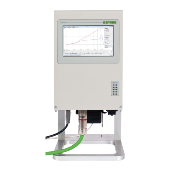
Brief Description The Sequence Controller AST40 is a controller with integrated power electronics to operate Series 311 DEPRAG MINIMAT–EC-Servo screwdrivers. The torques, rotating speeds, waiting times and direction of rotation can be individually adapted to the screw assembly tasks within the performance range of the screwdrivers. -
Page 13: Hardware Description
LED 10 24V external OK LED 11 Not in use LED 12 Not in use Figure 1: Front view of AST40 6.1.2 Connection side Interfaces GX1: DEPRAG MINIMAT– EC-Servo screwdriver GX2: I/O interface SPS1 GX3: I/O interface SPS2 GX4: I/O interface 3... -
Page 14: Interface Description
Interface description 6.2.1 MINIMAT–EC-Servo Screwdriver Designation: Plug connector: Hybrid circular connector 6.2.2 Power Supply Designation: Plug connector: Hirschmann STASEI 200 6.2.3 Ethernet Designation: Plug connector: Female connector RJ45 BULGIN PX0833 6.2.4 USB Designation: Plug connector: Female connector BULGIN PX0844/A/0M50/A 6.2.5 Emergency Stop Designation: Plug connector: Binder plug connector, 4 pin, round and straight... -
Page 15: I/O Interfaces
6.2.7 I/O interfaces 6.2.7.1 Voltage supply for I/O interfaces IMPORTANT 24V external: The integrated I/O module of the AST40 must be fed with 24V DC to use the inputs / outputs as well as the emergency stop circuit. This is done by feeding 24V DC via the pins 2/3 and 21/22 at plug connector GX2 (interface SPS ) or via pins 3 and 4 at plug connector GX9 (emergency stop). -
Page 16: Interface Sps 2
6.2.7.3 Interface SPS 2 Designation: Plug connector: SUB-D 25-pole (bushing) Pin Designation Type Pin Designation Type 14 GND internal 24V external 15 GND external Not in use Input n.c. Sequence 5 Input n.c. Sequence 6 Input Sequence 9 Input Sequence 7 Input Sequence 10 Input... -
Page 17: Fieldbus Interface (Optional)
6.2.8 Fieldbus interface (optional) 6.2.8.1 Profibus Designation: GX10 Plug connector: SUB-D 9-pole (bushing) Pin Designation Description RX/TX-P Send / Receive data ; Data line B PB_RTS PB-GND Mass (Ground): PB-5V Voltage supply +5V RX/TX-N Send / Receive data ; Data line A Table 8: Configuration Interface Profibus 6.2.8.2... -
Page 18: Start-Up
Start-up Dimension sheet Figure 3: Dimension sheet... -
Page 19: Assembly
Assembly WARNING Risk of fatal injury due to electrocution! Switch off the AST6 sequence controller at the main switch and disconnect the power plug before connecting the screwdriver! Commissioning may only be performed by qualified personnel. CAREFUL Injuries due to electricity and/or damage to the device Before connecting to the electrical supply, compare the rating of the AST40's sequence control system with the building's internal power supply (also see... - Page 20 Switch the AST40 sequence controller on using the main switch (GS1). ATTENTION Damage to the device due to overheating! Make sure that there is sufficient ventilation for the device. Do not operate the sequence controller in lying position and make sure, that there is free space at the ventilation slots on the back side of the device.
-
Page 21: Method Of Operation Of The Sequence Controller Ast40
Method of operation of the sequence controller AST40 Upon activation of the AST40 sequence controller, the process information display appears (also see Figure 36: Process display, Alternative 1 Figure 37: Process display, Alternative The MINIMAT–EC-Servo screwdriver is controlled via the I/O interface SPS1. If an optional fieldbus module is installed, then either the fieldbus module or the I/O interface can perform the control task. -
Page 22: Connection On A Master Controller Via The Fieldbus (Optional)
Connection on a master controller via the Fieldbus (optional) 7.6.1 Profibus DP / Profinet The device files for the Profibus, Profinet, EtherCAT and EtherNet/IP can be downloaded through the AST40 sequence controller's web interface (see 10.3.6.3 Fieldbus) 7.6.1.1 General Information All the required program modules to connect the Profibus and Profinet to a Siemens S7 –... -
Page 23: Software
7.6.1.2.2 Profinet Figure 5: Hardware configuration of Profinet 7.6.1.3 Software The following modules or UDTs are required to address the AST40 sequence controller by means of the Profibus or Profinet: Module Name Description Control module for the AST40 sequence controller FB12 AST40 This module must be loaded for every AST40 sequence controller... -
Page 24: Figure 6: Directory Of The Modules
Figure 6: Directory of the modules 7.6.1.3.1 Description of the transfer parameters (FB12) Designation Type Data type Description Input address from the hardware configuration I_Addr1 e.g. 256 Input address from the hardware configuration I_Addr2 e.g. 320 Input address from the hardware configuration I_Addr3 e.g. - Page 25 7.6.1.3.2 Description of the data structure of the control signals (UDT21) Designation Data type Description Clearance to start for the AST40 ReleaseStart BOOL This signal is currently not available yet! Clearance to start for the AST40 When the status of the start signal changes from "low" to Start BOOL "high", the pre-selected screwdriving program is started in...
-
Page 26: Table 11: Data Structure Of The Control Signals (Udt21)
Input 11 for the screwdriver program This input can be scanned in the screwdriver program of ProgIn11 BOOL the AST40 sequence controller in order to stop or continue the screwdriving program. Input 12 for the screwdriver program This input can be scanned in the screwdriver program of ProgIn12 BOOL the AST40 sequence controller in order to stop or continue... - Page 27 Emergency stop signal 2 is active Sto2active BOOL This signal has the status “high” when the Emergency Stop circuit is functioning properly. Reload signal Reload BOOL This signal is currently not available yet! Output 1 from the screwdriver program This output can be set or reset and queries in the SPS in ProgOut1 BOOL the screwdriving program of the AST40 sequence...
- Page 28 Cycle ended for F-Function FC_CycleDone BOOL This signal is currently not available yet! Lock part for F-Function FC_LockPart BOOL This signal is currently not available yet! Data is available This signal indicates that new screw data is available. DataAvailable BOOL This is reset by the AST40 sequence controller, if the signal “Data Saved”...
-
Page 29: Table 12: Data Structure Of The Status Signals (Udt22)
interface) This signal indicates the status of input 4 at the hardware interface. (see 6.2.7 I/O interfaces) System status This parameter indicates the system status of the AST40 – SysStatus screwdriving controller. (for possible status values, see 15.1 System error) Error Code ErrorCode WORD... -
Page 30: Table 13: Status Signal Error Codes
An incorrect output module has been entered in the hardware configuration. Output module 2 must be configured with "64 bytes out". Incorrect start address of the output module 2 at the interface parameter O_Addr2 Error while writing to the output module 3 (O_Addr3) Possible causes: ... - Page 31 7.6.1.3.5 Description of the data structure of the screwdriving data (UDT23) Designation Data type Description Program number fd_Prog The program number of the screwdriver program started previously is output here. Screw status The screwdriver status is output here in detail. fd_Status (for possible status values, see 15.2 Error in the Screwdriving...
- Page 32 Torque value of the Data backup fd_Torque2 REAL The torque value of the data backup (2) is output here Lower angle of rotation limit of the Data backup fd_minAngle2 DINT The set lower limit of the angle of rotation of the data backup (2) is output here.
-
Page 33: Table 14: Data Structure Of The Screwdriving Data (Udt22)
Torque value for an incorrect or improper screw joint fd_TorqueNOk REAL The torque value of an incorrect or improper screw joint is output here Lower angle of rotation limit for a faulty screw assembly fd_minAngleNOk DINT The set lower angle of rotation limit for a faulty screw assembly is output here. - Page 34 7.6.1.3.6 Data backup The command “Back up values” (Save values) can be used as frequently as required during the screwdriving sequence, but only the last three values will be backed up. In case of an error or a failure, the values are always saved. The value last saved is always available in the range fd_Step3 / fd_Torque3 / fd_Angle3.
-
Page 35: Ethernet/Ip
7.6.2 EtherNet/IP 7.6.2.1 General Information The device files for the Profibus, Profinet, EtherCat and EtherNetIP can be downloaded through the AST40 Web interface (see 10.3.6.3 Fieldbus) All necessary input files and example programs for the EtherNet/IP - connection to an AllenBradley controller are contained in the software packet DEPRAG_AST40EIP.zip. -
Page 36: Figure 7: Creating Ethernet / Ip - New Module
7.6.2.2.2 Creating the EtherNet / IP Module To create any EtherNet / IP Module use the following method: 1. In the "I/O configuration" right click on "Ethernet" and select "New Module": Figure 7: Creating Ethernet / IP - new module When using an ENET module (e.g. -
Page 37: Figure 8: Creating Ethernet / Ip - Select Module
2. Select the module "ETHERNET-MODULE – Generic Ethernet" and confirm with "Create". Figure 8: Creating Ethernet / IP – select module 3. Enter the settings and confirm with "OK". Figure 9: Creating Ethernet / IP – confirm settings... -
Page 38: Table 15: Creating Ethernet / Ip - Conform Settings
Parameter Value Description Freely selectable name of the fieldbus node (e.g. AST40_1, Name AST40_2...) Description Freely selectable description of the of the fieldbus node Comm Format Data - SINT Data format IP address IP address that is set on the AST40 (fieldbus setting). Input Assembly Instance Input... -
Page 39: Software - Import
7.6.2.3 Software - Import The following import files are required to control the AST40 using the EtherNet/IP: Name Type Description Add-On Add-On Instruction to control the AST40 incl. the data types AST40.L5X AST40_IN_FinalValues, AST40_IN_Signals and Instruction AST40_OUT_Signals Contains the data types AST40_IN_FinalValues, AST40_Cntr.L5X Data type AST40_IN_Signals and AST40_OUT_Signals... -
Page 40: Figure 11: Import Ast40.L5X - Confirm Import
2. Search for the file "AST40.L5X" (contained in DEPRAG_AST40EIP.zip) and confirm with "Import": Figure 11: Import AST40.L5X – Confirm Import 3. In the following dialog window user-specific changes can be made to the name "Final Name" and the description "Description" (it is recommended to keep the name and the description!), Then confirm with "OK". -
Page 41: Figure 13: Import Ast40.L5X - Menu Tree
4. The added elements are now visible in the menu tree: Figure 13: Import AST40.L5X – Menu tree 7.6.2.3.2 Import AST40_Cntrl.L5X 1. In the menu tree right click on "Data Types", "User-Defined" and select "Import Data Type": Figure 14: Import AST40_Cntrl.L5X – „Data Types“, „User-Defined“ and „Import Data Type“ 2. -
Page 42: Figure 16: Import Ast40_Cntrl.l5X - Final Name
3. In the following dialog window user-specific changes can be made to the name "Final Name" and the description "Description" (it is recommended to keep the name and the description!), Then confirm with "OK". Figure 16: Import AST40_Cntrl.L5X – Final Name 4. -
Page 43: Figure 18: Import Controller-Tags.csv - "Tags And Logic Comments
7.6.2.3.3 Import Controller-Tags.csv 1. Select under "Tools" "Import" "Tags and Logic Comments": Figure 18: Import Controller-Tags.csv – “Tags and Logic Comments” 2. Search for the file "Controller-Tags.csv" (contained in DEPRAG_AST40EIP.zip) and confirm with "Import": Figure 19: Import Controller-Tags.csv – “Import”... -
Page 44: Figure 20: Import Controller-Tags.csv - Error Display
3. A successfully completed import can be seen in the error display: Figure 20: Import Controller-Tags.csv – Error display 4. Display the controller tags: Figure 21: Import Controller-Tags.csv – Display controller tags IMPORTANT If several AST40 controllers are operated the number of array elements has to be increased. -
Page 45: Figure 22: Import Ast40_Control.l5X - "Import Routine
7.6.2.3.4 Import AST40_Control.L5X 1. Right click in a task in the menu tree (e.g. main program) and select "Import Routine": Figure 22: Import AST40_Control.L5X – “Import Routine” 2. Search for the file "AST40_Control.L5X" (contained in DEPRAG_AST40EIP.zip) and confirm with "Import": Figure 23: Import AST40_Control.L5X –... -
Page 46: Figure 24: Import Ast40_Control.l5X - Change „Final Name" And „Description
3. In the following dialog window user-specific changes can be made to the name "Final Name" and the description "Description" (it is recommended to keep the name and the description!), Then confirm with "OK". Figure 24: Import AST40_Control.L5X – Change „Final Name“ and „Description“ 4. -
Page 47: Figure 26: Import Ast40_Control.l5X - Description Of The Module
5. Description of the module: Figure 26: Import AST40_Control.L5X – Description of the module Current path 0: GSV: Used to determine the status on the EtherNet/IP - slave AST40: Call the "AST40 Add-On Instruction" IMPORTANT When several AST40 controllers are operated this current path should be duplicated and the variables adapted. -
Page 48: Figure 27: Import Ast40_Control.l5X - Add-On Instruction Call
6. Description of the Add-On instruction call Figure 27: Import AST40_Control.L5X – Add-On instruction call Designation Type Data type Description Validation condition of the EnableIn Bool module AST40 AST40 Add-On Instruction instance DataIn SINT[228] EtherNet/IP - module input data InOut EtherNet/IP - module output DataOut SINT[224]... -
Page 49: Software - Description Of Data Types
7.6.2.4 Software - description of data types 7.6.2.4.1 Description - data structure AST40_Cntrl Designation Data type Description IN_Signals AST40_IN_Signals AST40 inputs IN_FinalValues AST40_IN_FinalValues AST40 end values OUT_Signals AST40_OUT_Signals AST40 outputs Table 18: Data structure AST40_Cntrl 7.6.2.4.2 Description - data structure AST40_IN_Signals Designation Data type Description System OK... - Page 50 Lock part for F-Function Lock_Part BOOL This signal is currently not available yet! Cycle ended for F-Function FC_CycleDone BOOL This signal is currently not available yet! Reload BOOL Reload signal Output 5 -12 from the screwdriver program These outputs may be set or reset in the screwdriver uni_IO SINT program of the AST40 –...
-
Page 51: Table 19: Data Structure Ast40_In_Signals
Input 3 for the screwdriver program (Hardware interface) MI_IN_SchrPrg3 BOOL This signal indicates the status of input 3 at the hardware interface. (see 6.2.7 I/O interfaces) Input 4 for the screwdriver program (Hardware interface) MI_IN_SchrPrg4 BOOL This signal indicates the status of input 4 at the hardware interface. - Page 52 7.6.2.4.3 Description - data structure AST40_IN_FinalValues Designation Data type Description Program number Program number The program number of the screwdriver program started previously is output here. Screw status The screwdriver status is output here in detail. Status (for possible status values, see 15.2 Error in the Screwdriving Sequence)
- Page 53 Torque upper limit of the Data backup Torque_2_max REAL The set torque upper limit of the data backup (2) is output here. Torque value of the Data backup Torque_2 REAL The achieved torque value of the data backup (2) is output here.
-
Page 54: Table 20: Data Structure Ast40_In_Finalvalues
Torque lower limit for a faulty screwdriving operation Torque_NOK_min REAL The set torque lower limit for a faulty screwdriving operation is output here. Torque set point for a faulty screwdriving operation Torque_NOK_target REAL The set torque set point of the faulty screwdriving operation is output here. -
Page 55: Table 21: Data Structure Ast40_Out_Signals
7.6.2.4.4 Description - data structure AST40_OUT_Signals Designation Data type Description Error reset for F-Function RESET_ERROR BOOL This signal is currently not available yet! Part sensor for F-Function PART_SENSOR BOOL This signal is currently not available yet! Part release for F-Function CHANGE_PART BOOL This signal is currently not available yet! -
Page 56: Ethercat
7.6.2.4.5 Data backup The "Save values" command can be used as often as desired in the screwdriver operation, but however, only the last three values are saved. In case of an error or a failure, the values are always saved. The value last saved is always available in the range Step_3 / Torque_3 / Angle_3. -
Page 57: Users
Users The AST40 can manage up to 10 users. User 1 is the administrator. He can assign user names and passwords for an additional 9 users, configure the user type and can also activate or de-activate users (also see 9.2.5.3 User Administration). -
Page 58: Operation Using The Integrated Touch Display
Operation Using the Integrated Touch Display Control elements 9.1.1 Buttons The touch display has different operating areas: Display fields Display fields can be recognized by the pointed corners. They only have a display function. Input fields Input fields can be recognized by the rounded corners. Buttons Keys are buttons that can be used to access and control the menu, for example. -
Page 59: Selecting Between Several Options
9.1.3 Selecting between several options If more than two alternatives are available, e.g. for the language or the torque unit, then all the alternatives will be displayed in a separate key. The selected alternative is displayed with a dark background. Figure 29: Selecting between several options 9.1.4 Text and numerical input... -
Page 60: Description Of The Menu Structure
Description of the menu structure 9.2.1 Overview The main menu can be reached at any time by using the key on the left below the display. Figure 32: Main menu A user must be logged in to work with settings and to use menus which lead to the interruption of an automatic operation. -
Page 61: Registration
If a user logs into the process controller, then the list of open modules that has been saved for him will be loaded. The list of open modules is saved when the logged in user logs out. If no user is logged in, then the list is discarded as soon as a user logs in. 9.2.3 Registration User registration can be reached at any time using the list of open modules on the right below the display. -
Page 62: Process Data Menu Area
9.2.4 Process Data Menu Area Figure 35: Process Data Menu Area 9.2.4.1 Process display The process information can be reached at any time using the list of open modules on the right below the display and via the Main Menu. There are various alternatives for the process information display. -
Page 63: Statistics
Alternative 2: Figure 37: Process display, Alternative 2 The number and the name of the active program as well as the number of the step of the last screwdriving step are displayed in the top row. In the second line the date, time and duration of the last screw assembly is displayed. The status of the last screw assembly is displayed in the Status area. -
Page 64: Graphic
The statistics for the individual programs can be displayed via the menu item statistic. The prerequisite for this is that the Screwdriving program contains the command “Statistics” after the corresponding screwdriving step (also see 13.3 Statistic). The statistics are calculated from the measuring results of Measuring System 1. First, choose the number of the program for which you want to display the statistics. -
Page 65: System Menu Area
9.2.5 System Menu Area Figure 40: System Menu Area The System menu area contains all the information and settings for the entire system, i.e. for the sequence controller and the MINIMAT–EC-Servo Screwdriver. 9.2.5.1 System data The System Data menu displays the unchangeable data as well as the network settings of the AST40 sequence controller. -
Page 66: Figure 42: System Setup - Language
IMPORTANT A backup of the system settings can only be created via the web user interface (see 10.3.3.2.5 Create / Load Backup). Figure 42: System setup – Language Press the key , to get to the next settings page or , to go the previous settings page. -
Page 67: Figure 44: System Setup - Date / Time
Figure 44: System setup – Date / Time Press the key , to get to the next settings page or , to go the previous settings page. The general settings are located on the fourth page of the System Setups. Select the unit of measure for the torque by pressing on the required unit. -
Page 68: Figure 46: System Setup - General
Figure 46: System setup – General, Page 2 Press the key , to get to the next settings page or , to go the previous settings page. The general settings on the (optional) fieldbus module are located on the next page of the System Setups. -
Page 69: Figure 49: System Setup - Fieldbus, Ethernet/Ip Example
Figure 49: System setup – Fieldbus, EtherNet/IP example Figure 50: System setup – Fieldbus, Profibus example Figure 51: System setup – Fieldbus, ProfiNet example Press the key , to get to the next settings page or , to go the previous settings page. The alternatives of the process information can be selected on the next page. -
Page 70: User Administration
Figure 52: System setup – Process display selection Press the key , to get to the next settings page or , to go the previous settings page. Standard values can be set on the last page (see 11.2 Default values). Figure 53: System setup –... -
Page 71: Tool Data
Figure 54: System setup – Users Select the user you wish to create or modify and then press on the key Users that have not been prepared or were deleted again can be recognized by the fact that the button is set to “inactive”. Figure 55: Change user data You can set the selected user to active or inactive in the screen “Change user data”. -
Page 72: Screwdriver Settings
Figure 56: Screwdriver Data, Page 1 Press the key , to reach the next tool data page. 9.2.5.5 Screwdriver settings The settings for the connected MINIMAT–EC-Servo Screwdriver (also see Settings) can be performed in this menu, if a user is logged in. If no user is logged in, only the set values are displayed. -
Page 73: Menu Area - Screwdriving Sequence
Figure 58: Adjustment of the touch display 9.2.6 Menu Area – Screwdriving Sequence Figure 59: Menu Area – Screwdriving Sequence 9.2.6.1 Screwdriving Sequence Standard programs can be created and parameters of existing programs can be modified in the menu Screwdriving Sequence. If you wish to add additional steps or options, e.g. activate angle monitoring then this must be done via the web user interface (also see 10.3.4 Menu Area –... -
Page 74: Figure 60: Creating A Default Program
Figure 60: Creating a Default Program It is possible for you to create a default program, if there is no program available. Select the required screwdriving program. It will then be created by the AST40 sequence controller. Figure 61: Changing the Screwdriving Sequence To modify the program name, press on the entry field on the right beside “Program”. -
Page 75: Menu Area - Diagnosis
9.2.7 Menu Area - Diagnosis Various tests and diagnosis can be performed for the connected MINIMAT–EC-Servo Screwdriver and the AST40 sequence controller in the Diagnosis menu area. In order to be able to use the menus in the Diagnosis area, a user must be logged in. The menus “I/O Interface”... -
Page 76: Tool Test
Figure 64: Tool status – Page 2 Any warnings and errors are displayed on the left. The maximum acceleration to which the MINIMAT–EC-Servo screwdriver was exposed is displayed on the right. Press the key , to reach the next tool status page. Type on the button , to update the data. -
Page 77: Figure 66: Diagnosis I/O-Port, Inputs
Testing the inputs: After applying a signal at one input, the indication for the corresponding input lights up. Inputs at which there is a signal are shown in yellow (see “Screwdriving program 1” in the following figure), all other inputs are shown in grey. Testing the outputs: The outputs can be activated by means of the switches to the left beside the name. -
Page 78: Figure 67: Diagnosis I/O-Port, Program Choice
Figure 67: Diagnosis I/O-Port, Program choice (Page 2) All the inputs are located on the SPS1 (GX2) interface. Designation Description Program selection 0 Program selection 1 Program selection 2 Choice of screwdriving program 1 - 120 Program selection 3 Program selection 4 Program selection 5 Program selection 6 Table 24:... -
Page 79: Figure 69: Diagnosis I/O-Port, I/O Interface
Status of the last sequence was NOK Emergency stop 1 active Emergency stop signal 1 is active Emergency stop 2 active Emergency stop signal 2 is active Sequence 1 Output 1 in command "Set output" and "Reset output" Sequence 2 Output 2 in command "Set output"... -
Page 80: Fieldbus (Optional)
Press the key , to get to the next diagnosis page or , to go the previous diagnosis page. Figure 70: Diagnosis I/O-Port, Status (Page 5) The "Errors" field contains the error number of the last I/O interface error (see 15.1.5 I/O interface). -
Page 81: Figure 71: Diagnosis Fieldbus, Communication Flags
Figure 71: Diagnosis Fieldbus, Communication Flags (Page 1) Press the key , to get to the next diagnostics page or , to go the previous diagnosis page. Figure 72: Diagnosis Fieldbus, Inputs (Page 2) All the inputs for Profibus / Profinet are described in section 7.6.1.3.2 Description of the data structure of the control signals (UDT21) and for EtherNet/IP in section... -
Page 82: Figure 73: Diagnosis Fieldbus, Program Selection
Figure 73: Diagnosis Fieldbus, Program Selection (Page 3) All the inputs for Profibus / Profinet are described in section 7.6.1.3.2 Description of the data structure of the control signals (UDT21) and for EtherNet/IP in section 7.6.2.4.4 Description - data structure AST40_OUT_Signals. -
Page 83: Figure 75: Diagnosis Fieldbus, Universal Inputs And Outputs
All the outputs for Profibus / Profinet are described in section 7.6.1.3.3 Description of the data structure of the status signals (UDT22) and for EtherNet/IP in section 7.6.2.4.2 Description - data structure AST40_IN_Signals. Designation AST40 Profibus / Profinet EtherNet/IP System OK (HS + LT) SystemOk SYSTEM_OK ready... -
Page 84: System Image
Using EtherNet / IP all the inputs are described in section 7.6.2.4.2 Description - data structure AST40_IN_Signals, all the outputs are described in section 7.6.2.4.4 Description - data structure AST40_OUT_Signals. Designation AST40 Profibus / Profinet EtherNet/IP Sequence 5 ProgIn5 IN_Signals.uni_IO.0 Sequence 6 ProgIn6 IN_Signals.uni_IO.1... - Page 85 2. Press on "Generate". 3. Wait until you see that the system map was copied to the USB stick. 4. Then unplug the USB stick and send it to your DEPRAG consultant or directly to DEPRAG SCHULZ GMBH u. CO.
-
Page 86: Operations Using The Web-Based User Interface
10 Operations using the Web-based User Interface 10.1 Requirements 10.1.1 Hardware The web interface operates on any common PC or Notebook with a network card or a WLAN card. 10.1.2 Software The web-based user interface can be used with any common operating system, such as MS Windows, Linux, OS X ..., and functions with all common, current browsers. -
Page 87: Description Of The Menus
10.3 Description of the menus 10.3.1 Start Enter the IP address of the AST40 sequence controller (e.g. "http://10.10.25.108") in the browser's address bar and press Enter to load the web-based user interface. The IP address can be found in the system data, see 9.2.5.1 System data. -
Page 88: Figure 78: Start Page
Figure 78: Start page The start page displays the versions of the master control unit, the power unit, the display and the I/O interface as well as the type of fieldbus module that is installed. The IP addresses and MAC addresses of the master control unit and the display are also displayed. -
Page 89: The Menu Structure
10.3.2 The menu structure The menu has the following structure: System System Data System Setup General Fieldbus Date / Time Users Screwdriver Data Screwdriver Settings Tool Status Maintenance Log in Screwdriving Sequence Program 1 - 10 … Program 111 - 120 Process Data Final Values Statistics... -
Page 90: System Menu Area
10.3.3 System Menu Area The System menu contains all the information on the overall system, e.g. for the sequence controller and the MINIMAT–EC-Servo Screwdriver. 10.3.3.1 System data This page displays the unchangeable data as well as the network settings of the AST40 sequence controller. -
Page 91: Figure 82: System Setup
10.3.3.2.1 General information The general settings for the AST40 sequence controller can be dealt with here. Figure 82: System setup A description of the individual parameters can be found in Chapter Settings. In the case of printed text, you can specify what is to be printed if a screwdriving program uses the command "Print". -
Page 92: Figure 83: System Setup - Fieldbus, Example Without Fieldbus
10.3.3.2.2 Fieldbus All the general settings on the (optionally) available fieldbus module are found on this page. The specific settings for the built-in fieldbus module (see 11.1.1.2 Fieldbus system parameters (optional)) can also be entered on this page. Figure 83: System setup –... -
Page 93: Figure 85: System Setup - Fieldbus, Ethernet/Ip Example
Figure 85: System setup – Fieldbus, EtherNet/IP example Figure 86: System settings – Fieldbus, Profibus example... -
Page 94: Figure 87: System Setup - Fieldbus, Profinet Example
Figure 87: System setup – Fieldbus, ProfiNet example Click on "Set", to accept the settings into the AST40 sequence controller. Click on "Reset" to reset the changes on the page. Click on "Standard Values" to restore the standard values (see 11.2.1.3 Standard values for fieldbus systems (optional)). -
Page 95: Figure 89: User Administration
Log in as the user "admin" (see 10.3.1 Start, if you are not yet logged in or 10.3.3.7 Log if you are already logged in as a normal user). The password for the administrator in the delivery condition is 0000. Figure 89: User Administration First of all, select the User you want to create or want to modify from the drop-down list. -
Page 96: Screwdriver Data
10.3.3.3 Screwdriver data The essential data for the connected MINIMAT–EC-Servo Screwdriver is displayed on this page. Figure 90: Screwdriver data 10.3.3.4 Screwdriver settings The settings for the connected MINIMAT–EC-Servo Screwdriver (also see Settings) can be performed in this menu, if a user is logged in. If no user is logged in, only the set values are displayed. -
Page 97: Maintenance
Figure 92: Tool status 10.3.3.6 Maintenance Calibration of the display is started on this page (see 14.3 Calibrating the touch display). Figure 93: Adjustment of the touch display 10.3.3.7 Log in You can log in again on this page if the AST40 sequence controller had to be re-started or the web-based user interface remained open. -
Page 98: Menu Area - Screwdriving Sequence
10.3.4 Menu Area – Screwdriving sequence Select the required program using the submenu items. Screwdriving programs, that already exist, can be recognized by the fact that the program name is displayed after the program number, see Program 1 – 3 in the figure. Figure 94: Submenu item –... -
Page 99: Figure 96: Screwdriving Sequence - Complete Program
• Program title: Any designation with a character length limit of 16 characters. The title makes it easier to identify the program and has no effect on the screwdriving process. The program name must not contain any special characters. • Direction change: Determines if another main rotational direction applies for this program in the general settings. - Page 100 Open the screwdriving program you wish to delete by using the menu. Click on "Remove" at the top right beside the button "Print View“. IMPORTANT A program step, a complete program or all programs are deleted immediately without a confirmation prompt. View/process a program step: Select an available program step by clicking this step.
-
Page 101: Create / Load Backup
Printing out a screwdriving program: Open the screwdriving program you wish to print out by means of the menu. Click on the button "Print View" at the top right. Print out the screwdriving program by using your browser's print function. Clicking on the button "Normal View" returns you to the Program menu. -
Page 102: Process Data Menu Area
10.3.5 Process Data Menu Area The process data menu is used to display the statistics, the screwdriver curves and the connection or screw fitting results. 10.3.5.1 Final values The final values of the last seven days can be downloaded as CSV data (refer to 13.1 Final values). -
Page 103: Graphic
Figure 99: Statistics IMPORTANT Statistics values are only saved and analyzed if the "statistics" command in the screwdriving sequence is open. Click on "Delete" if you want to delete the statistics for the displayed program. All the statistical data can be deleted in the lower portion. If you have not entered a valid password, you cannot make any changes or delete any data. -
Page 104: Menu Area Extras
10.3.6 Menu Area Extras 10.3.6.1 Manuals You can read all the available manuals on the AST40 sequence controller or transfer these to your computer on this page. First, click on the language, e.g. English, and then select one of the available documents. Under the "General Information"... -
Page 105: Fieldbus
10.3.6.3 Fieldbus All the existing fieldbus drivers for the AST40 sequence controller can be downloaded on this page. Figure 103: Fieldbus 10.3.6.4 Updates New software can be loaded onto the control unit in the Updates menu (also see 14.2 Updating the software). -
Page 106: System Image (Only Visible For Logged In Users)
17.8 Optional software packages). To unlock these extensions please contact the DEPRAG sales department or your DEPRAG dealer. In order to be able to perform the activation, some information is required which must be contained in your order: •... - Page 107 Figure 106: System Image The system image contains fundamental information on the AST40 system. The following data can also be added: • all the screwdriving programs • screwdriving results • Curve displays on the latest screw assemblies. IMPORTANT It is strongly recommended that all available data be included in the system image.
-
Page 108: Settings
11 Settings 11.1 Description of the adjustable parameter 11.1.1 Controller 11.1.1.1 System Setting Parameters Parameters Description IP address The IP address with which the AST40 sequence controller can be reached on the network. IP address display The IP address with which the AST40 sequence controller reaches the display. -
Page 109: Fieldbus System Parameters (Optional)
be password protected. The password can consist of letters, numbers, space characters or hyphens. In the delivered state, the administrator password is always set to 0000. User type The user can either be a standard user or an expert. All of the functionalities are not available to standard users (see Users). -
Page 110: Minimat-Ec-Servo Screwdriver
11.1.2 MINIMAT–EC-Servo Screwdriver Parameters Description Offset gear available Indicates whether an adapter gear is available. Gear ratio Transmission ratio for the adapter gear Efficiency Effectiveness of the adapter gear Direction change Specifies whether the adapter gear causes change of direction. Table 35: Adjustable Parameters MINIMAT–EC-Servo Screwdriver 11.2 Default values... -
Page 111: Standard Values For Fieldbus Systems (Optional)
11.2.1.3 Standard values for fieldbus systems (optional) Profibus: Parameters Value Profibus address Table 38: Default values for Profibus Profinet: Parameters Value IP address 10.10.24.10 Net mask 25.255.0.0 Gateway 10.10.20.9 Station name nic 50 repns Table 39: Default values for Profinet EtherNet/IP: Parameters Value... -
Page 112: Screwdriving Strategies And Commands
12 Screwdriving Strategies and Commands 12.1 Screwdriving Strategy 12.1.1 Tighten / loosen to Torque The screwdriving strategy tighten / loosen to torque is a tightening / loosening process with stop control via parameter torque. Angle monitoring is possible as an option. Figure 107: Screwdriving Application to torque Strategy description:... -
Page 113: Extended Screwdriving To Torque
Parameters: The following parameters are used in the screwdriving Sequence: • Maximum time until the cut-out torque is reached (monitoring time) • Shut-off torque,shut-off torque upper/lower limits • RPM • Torque holding time • Angle measurment: yes / no if angle monitoring is active the following parameters are added: ◦... -
Page 114: Screwdriving - Tighten / Loosen To Angle
Not OK evaluation: The screwdriving sequence is evaluated as Not OK (faulty) if the final torque value is outside the preset limits or the maximum screwdriving time has been exceeded. If angle monitoring is active the screwdriving sequence is evaluated as Not OK, if the angle value is outside the preset limits. -
Page 115: Figure 110: Loosening On Angle
Figure 110: Loosening on Angle Strategy Description: At the start of the screwdriving sequence time monitoring and angle measurement is started. Cyclic torque measurements are performed. Shut-off criteria: The screwdriving process is ended once the • shut-off angle is achieved •... -
Page 116: Fasten / Loosen To External Stop-Signal
12.1.4 Fasten / Loosen to external Stop-Signal The screwdriving strategy Fasten/Loosen to External Stop-Signal is a screwdriving process with switch off to external signal. Figure 111: Fasten / Loosen to external Stop-Signal Sequence of the Screwdriving Strategy: • at the start of the screwdriving start of the screwdriver with preselected speed and time monitoring •... -
Page 117: Find
12.1.5 Find The screwdriving sample find can be used to facilitate threading the screw. Sequence of the Screwdriving Strategy: At the start of the screwdriving level the time monitoring and the angle measurement are started. Cyclic torque measurements are performed. Switching -Off Criteria: The screwdriving sequence is completed when •... -
Page 118: Friction Value Package (Optional)
12.1.6 Friction Value Package (optional) 12.1.6.1 Friction Value Measurement The function of the screwdriving Strategy is the tightening of a screw, while considering the friction value prior to screw head contact with the mating surface. The calculated friction value is applied as a factor to the preset torque value Figure 112: Friction Value Measurement Shut-off criteria:... -
Page 119: Screwdriving With A Differential Torque
Parameter: The following parameters are used in the screwdriving sample: • Maximum time Maximum time until the screwdriving level is aborted • Friction measurement angle Input of the angle range in which the friction monitoring should be active. • Friction value creation: Mean value/maximum value selectively the maximum value or mean value of the friction value can be used to determine the friction torque. - Page 120 Shut-off criteria: The screwdriving process is ended once the • Preset Shut-off torque value is achieved (variable based upon the addition of the friction value and the fixed diferential torque value) • A calculated Friction value is achieved • the maximum screwdriving time (time monitoring) is exceeded Analysis: OK evaluation: The screwdriving Sequence is considered OK (fault free), if the screwdriver...
-
Page 121: Screw Assemblies Depending On Friction
• Angle monitoring: yes / no Monitoring of the angle with a window angle if the angle monitoring is switched on, the following parameters are added: ◦ Swelling moment Input of the torque from when the angle monitoring should be started (compare point 1 in Figure 90:). - Page 122 Analysis: OK evaluation: The screwdriving sequence is considered OK (fault free), if the shut-off occurs via torque and and the differential value is whithin the preset limits. If the Angle monitoring option is active the final angle value must be within the preset limits.
- Page 123 • Differential Torque Input of the differential final torque The actual target torque - results from the sum of the determined friction torque and the differential moment o Minimum differential torque Lower limit of the differential final torque. The actual torque lower limit results from the sum of the lower limit of the friction torque and the lower limit of the differential torque.
-
Page 124: Commands
12.2 Commands 12.2.1 Waiting for input Waits for an input Switching to the next sequence step will occur when the input is high. Parameters: • Maximum waiting time • input number 12.2.2 Setting the output Sets an output. Parameter: • Output number •... -
Page 125: Printing
12.2.8 Printing Outputs the results of the preceding screwdriving stage to the serial printer interface (also 13.4 Print output). 12.2.9 Hold position Hold the screwdriver tension position Parameter: • Holding time... -
Page 126: Documentation
13 Documentation 13.1 Final values If the command 'save value' is used in the screwdriving program, then the screwdriving results are stored in a CSV data file and can be loaded from the controller via the web interface (see also 10.3.5.1 Final values). - Page 127 Value Description Date Date of screw assembly Time Time of screw assembly Program Number Program used Status Status, also see 15.2 Error in the Screwdriving Sequence Total Time Total duration of the program Step1 Step number of the first saved step MinTorque1 Torque lower limit of the first saved step TargetTorque1...
-
Page 128: Curve Display
13.2 Curve display A screwdriving curve is created for every screwdriving process with the AST40 sequence controller. This can be viewed or saved in different ways. • Displayed directly on the control unit in the Process Information menu area Curve Display •... -
Page 129: Statistic
• Sensor 2 torque (if available) • Sensor 2 angle (if available) 13.3 Statistic If the command "statistic" is used in the screwdriving program then in the sequence controller AST40 a statistic is kept about the last 100 values for the respective program. The statistics are calculated from the measuring results of Measuring System 1. - Page 130 system 2 (Redundancy) Angle measuring angle_red system 2 Value unit 1080 ° (Redundancy) Torque motor torque_plausi Value unit 0,215 Nm (Plausibility) Angle motor angle_plausi Value unit 1080 ° (Plausibility) prog Program number Value errornum Status / Error number Value errortext Status / Error text Error message torque underrun...
- Page 131 IMPORTANT The values " torque_red“ and "angle_red“ are only available if the connected MINIMAT–EC-Servo screwdriver is equipped with a second measuring system. IMPORTANT Statistical values can only be printed if the command "Statistics" is inserted ahead of the print command in the screwdriving process. At the time of delivery the standard format is: @date_iso @time PG: @prog ST: @step TQ: @torque AN: @angle @errortext Issue:...
-
Page 132: Maintenance And Servicing
14.1 General Incorrect disassemb ly or assembly can lead to injury of an operator and damage of the ma- chine. Disassembly and assemb ly work may only be carried o ut by DEPRAG or qualifi ed personnel . Recommendations should help to uphold warranty claims. -
Page 133: Updating The Software
14.2 Updating the software 14.2.1 Main controller and display Updating can only be done via the web interface. Log in as described in section 10.3.1 Start. Click on Updates in the Tools menu area (also see 10.3.6.4 Updates). In order to update the main controller including the display, enter the file name and path in the input field and click "Load". -
Page 134: Calibrating The Touch Display
14.3 Calibrating the touch display It is possible that the touch display may need to be re-calibrated due to aging and wear. IMPORTANT Calibration must be carried out directly on the display, even if you start the calibration process through the web-based user interface. IMPORTANT Use the Touch-Pen (see 17.7... -
Page 135: Error Display And Troubleshooting
15 Error display and troubleshooting 15.1 System error If you discover that the AST40 sequence controller is defective, please send it to DEPRAG. Please do not try to troubleshoot or rectify any electrical fault on your own under any circumstances whatsoever. 15.1.1 MINIMAT–EC-Servo Screwdriver... -
Page 136: Table 46: System Error - Power Unit
Communication has become unsynchronized Troubleshooting not possible Brake resistor overloaded Check the fitting process and adjust it if necessary. I²t has triggered If required, consult the DEPRAG Service Department. Braking resistance overloaded Troubleshooting not possible Table 46: System error - power unit... -
Page 137: Main Controller
Fieldbus not available! longer needs to be used, deactivate the fieldbus in the settings. Software versions of master control Please contact the DEPRAG Service unit and power unit do not match! Department. Screwdriver and power unit do not Ensure that you have installed the correct AST40. -
Page 138: Table 49: System Error - I/O Interface
Internal supply voltage outside of 21-28 V External supply voltage outside of 21-28 V Total current error I²C bus not opened Module not found Please contact the DEPRAG Read failed Service Department. Write failed Table 49: System Error - I/O Interface... -
Page 139: Error In The Screwdriving Sequence
Enter a program number between than 100 not supported 1 and 100. General fault general fault The screw connection was Power unit has Please contact the DEPRAG terminated, because the power stopped Service Department. unit has switched off. General error general error Table 50:... -
Page 140: Help With Faults
Table 51: Error Rectification If you discover that the AST40 sequence controller is defective, please send it to DEPRAG. Please do not try to troubleshoot or rectify any electrical fault on your own under any circumstances whatsoever. -
Page 141: Accessories
17 Accessories 17.1 Power cord Designation Product–Code Power cable KN-AST10/40-EU 385443 A Power cable KN-AST10/40-US 385443 B Power cable KN-AST10/40-China 385443 C 17.2 Emergency Stop Connector Plug-in connector to link interface GX9. Designation Product–Code Plug 827507 17.3 AST40 – PC Connection Cable The cable is used to interconnect the AST40 sequence controller with the company network or the PC's network interface. -
Page 142: Stand
Special pen for facilitating operation on the touch-screen display. Designation Product–Code 832190 All texts are also available on the web via download at www.deprag.com. 17.8 Optional software packages 17.8.1 Friction value software package The software package friction values contain the following additional screwdriving Sequences: •... -
Page 143: Datalogger
17.8.2 DataLogger Figure 115: DataLogger The data logger provides the possibility to record the end value data sets from up to 10 sequence controllers (AST) and to archive them. The DataLogger program can be downloaded free of charge via the web interface of the sequence controller AST40. -
Page 144: Graph10 - Curve Overlapping
17.8.3 GRAPH10 – curve overlapping Figure 116: GRAPH10E The GRAPH10(E) program can be downloaded free of charge via the web interface of the sequence controller AST40. However, the use of the curve overlapping is subject to cost. Designation Part no. Curve overlapping release 202698 GRAPH10E... -
Page 145: Tc30-Pc Statistics
17.8.4 TC30-PC Statistics Figure 117: TC30-PC Statistics program Statistics software for evaluation of the screwdriving data and calculation of average value, standard deviation and cmk value. For the graphic display several alternatives may be selected. The TC30-PC Statistics program can be downloaded free of charge via the web interface of the sequence controller AST40. -
Page 146: Glossary
18 Glossary Term Description If the clearance for start is activated then the screwdriver will only Clearance for start start if there are 24V at the clearance to start input. Otherwise the controller is not ready to screw. Command General program step to create the screwdriving sequence (e.g. setting the output). - Page 147 error free Power unit Component for the motor control of the screwdriver Process ability index (C = total specific torque tolerance of the Connection: 6 Sigma (s). This index just provides information about the spread angle of the torque values. ...
- Page 148 Industry bus for the control and data exchange with sequence Profinet control resp. the base station Selection of the program to be started. The program selection can Program selection occur in different ways, depending on control and selected screw types (e.g. I/O interface at the control, direct program switching at the screwdriver, etc.) Communication interface in a network.
-
Page 149: Decommissioning And Storage
19 Decommissioning and storage NOTICE ALL DOCUMENTATIONS! Please read and consider the attached booklet safety instructions 016000 (see chapter environmental regulations, storage and disposal, see page 37). For shut-down perform the following steps: No. Action Disconnect the electric equipment of the machine / device from power supply (switch off main switch and pull out main plug). -
Page 150: Technical Data
20 Technical Data Type AST40 385588 A Part no. Number of MINIMAT–EC-Servo Screwdrivers that can be connected IP54 Protection class Operating temperature [°C] 0 – 45 Dimensions [cm] B x H x T 23,2 x 31,5 x 20,5 Weight [kg] Voltage [V] 100 –... -
Page 151: Ec Declaration Of Incorporation
the relevant technical documentation in accordance with part B of ANNEX VII will be transmitted in re- sponse to a reasonable request by the national authorities in printed form or electronic form (pdf) Manufacturer DEPRAG SCHULZ GMBH u. CO. P.O. Box 1352, Germany-92203 Amberg Carl-Schulz-Platz 1, Germany-92224 Amberg Mr. -
Page 152: Service Locations And Authorized Partners
If you need any further information then please either contact your representative or us directly at DEPRAG SCHULZ GMBH u. CO. During business hours our Service-Hotline + 49 (0) 700 00 371-371 is available for German and English speakers. - Page 153 DEPRAG SCHULZ GMBH u. CO. P.O. Box 1352, 92203 Amberg, Germany Carl-Schulz-Platz 1, 92224 Amberg, Germany Service Hotline +49 (0) 0700 00 371-371 +49 (0) 9621 371-0 Fax: +49 (0) 9621 371-120 Internet: http://www.deprag.com e-mail: info@deprag.de...
Need help?
Do you have a question about the AST40-1 and is the answer not in the manual?
Questions and answers