Table of Contents
Advertisement
Quick Links
013444en
NOTICE ALL DOCUMENTATIONS!
Before beginning work the safety instructions (pink) and all documentation
referring to this machine have to be read through carefully. Always follow the
instructions during operation. These safety instructions constitute part of the
operating instructions.
Give this booklet and the appropriate operating instruction booklet to the operator.
DEPRAG SCHULZ GMBH u. CO.
PO Box 1352,
Kurfürstenring 12-18, D-92224 Amberg
Service-Hotline
Tel
Fax
Internet:
E-Mail:
Operating manual
-ORIGINAL-
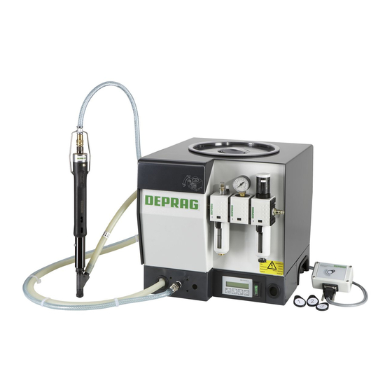
Feeder Controller
SZG Controller 6 - HSF
362625 B
D-92203 Amberg
+49 (0) 0700 00 371-371
(09621) 371-0
(09621) 371-120
http://www.deprag.com
info@deprag.de
Advertisement
Table of Contents

Related Manuals for Deprag SZG Controller 6


Summary of Contents for Deprag SZG Controller 6
- Page 1 013444en Operating manual -ORIGINAL- Feeder Controller SZG Controller 6 - HSF 362625 B NOTICE ALL DOCUMENTATIONS! Before beginning work the safety instructions (pink) and all documentation referring to this machine have to be read through carefully. Always follow the instructions during operation. These safety instructions constitute part of the operating instructions.
-
Page 2: Table Of Contents
FEEDING TECHNOLOGY Contents INTRODUCTION..........................4 CONTROLLER FUNCTION......................5 OPERATION..........................6 DESCRIPTION OF THE DISPLAY ....................6 DESCRIPTION OF THE KEYPAD....................6 DESCRIPTION OF THE MENU...................... 6 1.1.1 MENU SECTIONS APPEAR AS FOLLOWS:.................. 7 3.3.1 MENU ............................8 FUNCTIONS AND SETTINGS ....................... 9 RELOAD............................ - Page 3 The controller 362625 B is based on the feeder controller SZG CONTROLLER 6 and is only to be used in connection with a sword feeder from DEPRAG SCHULZ GMBH u CO. Please pay attention to the further instructions for use in the technical...
-
Page 4: Introduction
FEEDING TECHNOLOGY Introduction The electronic sequence controller carries out all necessary controller tasks for the operation of the feeder series 8. It is designed for optimal setting of the program sequence via the simple integrated menu for any application. To optimise the feed part cycle essentially the following points are decisive: •... -
Page 5: Controller Function
FEEDING TECHNOLOGY Controller function The complete cycle of the feeder is made up of the following phases: • Minimum driver run time t • New cycle delay t • Air-push delay t • Part air-push delay t • Separator forward time t Start Supporting Air-push... -
Page 6: Operation
FEEDING TECHNOLOGY Operation Description of the display The factory settings of the feeder controller display a standard screen. A different display screen can be selected in the menu. Image 2: Display with standard screen Description of the keypad BUTTON DESCRIPTION SELECT THE MENU SELECT MENU SECTION SAVE AND LEAVE MENU SECTION... -
Page 7: Menu Sections Appear As Follows
FEEDING TECHNOLOGY 1.1.1 Menu sections appear as follows: CHANGE USER: Select user TIMES: Time settings for current user MIN. DRIVER TIME Minimum driver run time NEW CYCLE DELAY New cycle delay AIR-PUSH DELAY Air-push delay SEP. FORWARD Separator forward time PART AIR-PUSH Feed part air-push HS-SEGMENT UP... -
Page 8: Menu
FEEDING TECHNOLOGY 3.3.1 Menu ---------> CHANGE USER ---------> TIMES ---------> MIN.DRIVER TIME ---------> NEW CYCLE DELAY ---------> AIR-PUSH DELAY ---------> SEP. FORWARD ---------> PART AIR-PUSH ---------> HS-SEGMENT UP ---------> HS-SEGMENT DOWN ---------> CHANGE LANGUAGE ---------> SUPPL. CONDITION ---------> RFID ---------> CHANGE PASSWORD --------->... -
Page 9: Functions And Settings
Press the button again to set the output back to 0. Restore factory settings In the menu section SUPPL. CONDITION the factory settings from DEPRAG can be restored. The following settings are then replaced with the factory set values: •... -
Page 10: Rfid
FEEDING TECHNOLOGY RFID Image 3: Reader with connection cable and three RFID tags In menu section RFID the RFID tags (coded chips) can be programmed for all users. The user is shown at the end of the line in brackets. Use buttons to choose the required user number. -
Page 11: Fill Level Sensor (Optional)
FEEDING TECHNOLOGY If an inlet control is used then this monitors whether a feed part is in the separator. If there is no feed part present at the start of a cycle or 60 seconds after the last separator procedure then a warning signal is set off. -
Page 12: New Cycle Delay
FEEDING TECHNOLOGY 4.8.2 New cycle delay The new cycle delay is the length of time between the moment the screwdriver switches off and the beginning of the separation and feeding process of the next feed part. Minimum time: sec. Maximum time: sec. -
Page 13: Password
FEEDING TECHNOLOGY Password In menu section CHANGE PASSWORD a password for the menu can be set or changed. The standard password is 0000. Any value from 0001 to 9999 can be set. Use the buttons to set the first number. Confirm the number with and then set the other numbers in the same way. -
Page 14: Language
FEEDING TECHNOLOGY 4.10 Language The controller software is available in several languages. The language can be selected via menu section LANGUAGE. Use the buttons to move through the languages available. The current language is marked by an asterisk. Press the button to select the language you want for the display, an asterisk is set. -
Page 15: Display
FEEDING TECHNOLOGY 4.11 Display In menu section DISPLAY you can select the display screen which should appear during normal operation. Use the buttons to move through the options. The current selection is marked by an asterisk(*). Press the button to select the required option and an asterisk is set. Use the button to leave the menu section. -
Page 16: Combined
FEEDING TECHNOLOGY 4.11.4 COMBINED This screen combines the displays for the counter and feed part assembly time. Image 9: Display counter and part assembly time... -
Page 17: Optional Accessories
FEEDING TECHNOLOGY Optional Accessories Inlet control / hose screw sensor (hose) Hand feeders can be equipped with an inlet control or hose screw sensor. The presetting of each inlet control or hose screw sensor is carried out at the factory. Fill level sensor (bin) Hand feeders can be fitted with a fill level sensor. -
Page 18: Rfid
FEEDING TECHNOLOGY RFID For the RFID function a reader (so-called Identbox) is required, as well as a connection cable. Image 10: Reader with connection cable and three RFID tags ORDER NO. DESCRIPTION TYPE 385505 A IDENTBOX RFID 201829 RFID CHIP RFID TAG KEYRING 385514 A CONNECTION CABLE... -
Page 19: Pc-Software
FEEDING TECHNOLOGY PC-Software The PC software SZG-Manager allows easy operation of the feeder controller. Using this software the set user times can be downloaded from the controller and saved onto a PC. Alterations to the times can be carried out on PC and then sent back to the controller. Image 11: Main window of the PC software Image 12: Display of the set user times ORDER NO. -
Page 20: Cable Layout
FEEDING TECHNOLOGY Cable layout Voltage- RFID Valve block Inputs Image 13: the controller from backside Providing of external ping for TYPE x811 with controller Image 14: Cable connection for sword feeder TYPE x811 with integrated controller Providing of external ping for TYPE 0811-2-EP/1,5 ATTENTION: The allocation counts for both 3-pole sockets inside the feeder. -
Page 21: Signal Duration For Start 1 - 2 (Only Type Ep)
FEEDING TECHNOLOGY Signal duration for START 1 – 2 (only TYPE EP) START 200 ms Inputs THREE POLE PLUG / INPUTS NO. / 1811 0811-EP 0811-2-EP COLOUR 1 / NONE START 1 START 1 START 1 2 / WHITE START 2 INLET CONTROL 1 3 / RED RING PROXIMITY... -
Page 22: Plug Configuration
FEEDING TECHNOLOGY FOUR POLE PLUG COLOURS WHITE RFID / SERIES INTERFACE Plug configuration THREE POLE PLUG FOUR POLE PLUG INPUTS RFID / SERIES INTERFACE CONFIGURATION CONFIGURATION SIGNAL Outputs 1811 0811-EP 0811-2-EP SUPPORTING BLOW SUPPORTING BLOW OUTPUT 1 SUPPORTING BLOW AIR OUTPUT 2 AIR PUSH AIR PUSH... -
Page 23: Error Messages / Operational Status
FEEDING TECHNOLOGY Error messages / Operational status If any errors or malfunctions occur during operation then an error message is displayed on screen. The following errors could occur: FAULT REASON SOLUTION If necessary refill the bin, inlet control Remove parts which recognised a part for 60 seconds. -
Page 24: Service Stations And Authorized Partners
Service stations and authorized partners You will find DEPRAG service stations in germany and also the authorized DEPRAG partner stations worldwide at our home page www.deprag.com DEPRAG SCHULZ GMBH u. CO. Postfach 1352, D-92203 Amberg Kurfürstenring 12-18, D-92224 Amberg Service-Hotline...
Need help?
Do you have a question about the SZG Controller 6 and is the answer not in the manual?
Questions and answers