Table of Contents
Advertisement
Advertisement
Table of Contents

Related Manuals for Toro Micro-Master Series


Summary of Contents for Toro Micro-Master Series
- Page 1 ® Micro-Master Series Micro-Master Touch User Guide © 2014 Toro Australia Pty Ltd...
- Page 3 Micro-Master Series by Toro Micro-Master Touch User Guide by Toro Australia Pty Ltd Congratulations on purchasing a Micro-Master Touch Irrigation Controller. The Micro-Master Touch Controller represents a significant change in the capabilities of irrigation controllers. Some of the Micro-Master Touch features include...
- Page 4 Micro-Master Touch User Guide © 2014 Toro Australia Pty Ltd All rights reserved. No parts of this work may be reproduced in any form or by any means - graphic, electronic, or mechanical, including photocopying, recording, taping, or information storage and retrieval systems - without the written permission of the publisher.
-
Page 5: Table Of Contents
Multi Station Programs ........................... Overview and Operation ........................... Program Edit Screens ................................43 9.2.1 Program List 9.2.2 Program Edit - Sequential ................................44 ................................46 9.2.3 Program Edit - Grouping © 2014 Toro Australia Pty Ltd Ver 1.2, June 2014... - Page 6 Flow Meter List ................................91 ................................92 14.4.3 Flow Meter Edit 14.4.4 Flow Meter Status and Totals ................................94 ........................... 14.5 Aggregate Flow Meters 14.5.1 Overview and Operation ................................94 © 2014 Toro Australia Pty Ltd Ver 1.2, June 2014...
- Page 7 ........................... 18.2 Number Edit ........................... 18.3 Time Edit ........................... 18.4 Group Edit ........................... 18.5 Allocated Station Edit ........................... 18.6 Control / Sensor Selection ........................... 18.7 Log View TMR1 Series Remote © 2014 Toro Australia Pty Ltd Ver 1.2, June 2014...
- Page 8 Fault Finding Flow Chart ........................... 21.3 Fault Finding - Possible Cause ........................... 21.4 Diagnostics ........................... 21.5 Checking Field Wiring and Valve Currents ........................... 21.6 Voltage On Unused Pins Copyright Notice Glossary of Terms © 2014 Toro Australia Pty Ltd Ver 1.2, June 2014...
-
Page 9: Introduction
Introduction The Micro-Master Touch Irrigation Controller is the latest in a long line of reliable Australian designed and built controllers brought to you by Toro. It uses the latest in microprocessor technology, including a full colour, touch screen LCD display. -
Page 10: Do's & Dont's
Always use a licensed support person or return the unit for repair. · In areas with known voltage fluctuations, or frequent 'brownouts', we recommend that the controller be connected to a UPS and surge protection device. © 2014 Toro Australia Pty Ltd Ver 1.2, June 2014... -
Page 11: About This Manual
A diagram of the real world example is shown below. Tank Full Almost Full (Circulation Stop) Tank Empty Treelot Treelot Zone 1 Zone 2 Figure 1 - Real World Example Schematic © 2014 Toro Australia Pty Ltd Ver 1.2, June 2014... -
Page 12: Controller Part Numbers
Micro-Master Touch Front Panel MMTOUCH-MTH Micro-Master Touch Motherboard MMTOUCH-POW Micro-Master Touch Power Supply MMTOUCH-TRN Micro-Master Touch Mains Transformer MMTOUCH-MIP Micro-Master Touch Mains Input Protection Module MMTOUCH-ISO Micro-Master Touch Isolation Module © 2014 Toro Australia Pty Ltd Ver 1.2, June 2014... - Page 13 Micro-Master Touch User Guide The diagram below shows the breakdown of a Micro-Master Touch Master Unit. Figure 2 - Micro-Master Touch Master Unit - Exploded Diagram © 2014 Toro Australia Pty Ltd Ver 1.2, June 2014...
- Page 14 Micro-Master Touch User Guide The diagram below shows the breakdown of a Micro-Master Touch Remote Unit. Figure 3 - Micro-Master Touch Remote Unit - Exploded Diagram © 2014 Toro Australia Pty Ltd Ver 1.2, June 2014...
-
Page 15: Installation Instructions
A wide range of modules are available for both the communication slots on the processor board and expansion slots on the motherboard. Both employ a similar method of mounting and are easy to install or remove. © 2014 Toro Australia Pty Ltd Ver 1.2, June 2014... - Page 16 An example of a motherboard is shown in Figure 5. This motherboard has been populated with 2 8 Station Relay Modules (MMTOUCH-STN) in Expansion Module numbers 1 and 2, an RS485 Remote Expansion Module (MMTOUCH-485E) in Expansion Module number 6 and a Radio-Master for Touch © 2014 Toro Australia Pty Ltd Ver 1.2, June 2014...
-
Page 17: Master/Remote Selection
For Remote Unit number 2, the number 2 switch should be ON, all others OFF. For Remote Unit number 3, the number 3 switch should be ON, all others OFF. © 2014 Toro Australia Pty Ltd Ver 1.2, June 2014... -
Page 18: Connecting Valve Wire
When all valve wires have been connected, ensure that all holes and spaces between valve wires are sealed with a silicone sealant or similar. This ensures that insects, ants and vermin cannot enter the controller. © 2014 Toro Australia Pty Ltd Ver 1.2, June 2014... -
Page 19: Earth Stake
The Touch Series controllers can be easily changed to operate on 12VDC. It should only be used with caution as valves must be fitted locally as wires carrying DC current should not be installed under ground because of electrolysis. Ideal installation when hydraulic valves are used. © 2014 Toro Australia Pty Ltd Ver 1.2, June 2014... - Page 20 2. Plug in the 12VDC adaptor plug supplied with the controller. 3. Connect the RED lead to +12VDC. 4. Connect the BLACK lead 0VDC. 5. Connect Earth stake as described in the Earth Stake installation instructions. © 2014 Toro Australia Pty Ltd Ver 1.2, June 2014...
-
Page 21: Controller Setup And Configuration
Radio-Master for Touch radio addresses or RS485 addresses. Selecting the scan option on the radio address screen will search the controller network for all Radio-Master for Touch or RS485 based modules. © 2014 Toro Australia Pty Ltd Ver 1.2, June 2014... - Page 22 Full access allows users access to all areas of the controller. Only users with full access can change the PIN numbers. If a PIN number is forgotten, please contact Toro Technical Services for assistance. Communication Options The controller supports a number of communication options for connection to outside computing resources.
-
Page 23: Setup Selection
Pressing this icon displays the Global Setup screen to allow reset of the controller memories, and for setting controller global enable/disable control. Unit Setup and Configuration Pressing this icon displays the Unit Setup screen to allow configuration of Units and Expansion Modules. © 2014 Toro Australia Pty Ltd Ver 1.2, June 2014... - Page 24 Diagnostic Setup and Configuration Pressing this icon displays the Diagnostics screen to allow diagnostic testing of the controller front panel. Help Pressing this icon displays a help screen explaining the options available. © 2014 Toro Australia Pty Ltd Ver 1.2, June 2014...
-
Page 25: System Setup And Upgrade
The firmware update process does not perform any checks for operating programs or input conditions. The user must ensure that all controller programs are stopped before attempting a firmware upgrade. © 2014 Toro Australia Pty Ltd Ver 1.2, June 2014... -
Page 26: Unit Configuration
Remote Units can be enabled or disabled. Disabling an Remote Unit prevents stations on that Remote Unit from being operated for example, to allow maintenance to occur. Clicking on the tick (cross) will change the Unit to disabled (enabled). © 2014 Toro Australia Pty Ltd Ver 1.2, June 2014... -
Page 27: Expansion Module Configuration
Radio-Master for Touch RMT800 Field Module with radio address 00 13 a2 00 40 93 ce 59. The module is version 1.0, serial number 201 and was manufactured in May 2014. © 2014 Toro Australia Pty Ltd Ver 1.2, June 2014... - Page 28 Scan Expansion Modules This icon will cause a scan of the selected Remote Unit to determine the current configuration of each expansion module in the Remote Unit. © 2014 Toro Australia Pty Ltd Ver 1.2, June 2014...
-
Page 29: Radio-Master For Touch Field Modules
The Solar Panel Mounting Plate has been designed to maximise the average available solar power whilst reducing wind resistance and providing ease of assembly. The angle of the Solar Panel has © 2014 Toro Australia Pty Ltd Ver 1.2, June 2014... - Page 30 Ensure the RM101 Plug Pack is not plugged into the 240V mains wall socket. Remove the connector from the cable by cutting the 2.1mm plug from the RM101 Plug Pack cable. © 2014 Toro Australia Pty Ltd Ver 1.2, June 2014...
- Page 31 4 with + and – positions. The – position goes to ground, and the + position to the sensor output as shown in Figure 14. RMT440D Inputs Figure 14 - RMT440D Connection Schematic © 2014 Toro Australia Pty Ltd Ver 1.2, June 2014...
- Page 32 To set a new channel number, ensure that the unit is turned on, then, in order, one button at a time, press SET, CHANNEL and the number of the new channel to use (1 to 8). You will have 5 seconds © 2014 Toro Australia Pty Ltd Ver 1.2, June 2014...
- Page 33 PWR – Shows power to the module and the state of the radio connection. A solid ON or OFF indicates a power issue, or a radio issue with the radio being unable to join the radio network. A © 2014 Toro Australia Pty Ltd Ver 1.2, June 2014...
-
Page 34: Communication Module Options
Repeated pressing of the selected valve will turn the valve on and off. Communication Module Options The Communication Option screens are displayed by pressing the icon on the Setup Selection screen. Figure 16 - Communication Module Parameters © 2014 Toro Australia Pty Ltd Ver 1.2, June 2014... - Page 35 Clicking on an item will select the item, changing the background of the item to light blue. Selecting the button and then clicking Edit will display an appropriate screen to allow modification of the selected communication parameter. © 2014 Toro Australia Pty Ltd Ver 1.2, June 2014...
-
Page 36: Pin Number Setup
Selecting the button and then clicking Edit will display the Number Edit screen. Lost PIN If a Full Access PIN number is forgotten, no access to any function is possible. Please contact Toro Technical Services for assistance. Commissioning Table Use the Commissioning Sheet (Table 1) on the next page to fill in commissioning data for later reference. - Page 37 Micro-Master Touch User Guide Micro-Master Touch Controller Output Commissioning Sheet Unit No. Wire Colour / Station Valve Valve Location Radio Comments Number Current Address Table 1 - Output Commissioning Sheet © 2014 Toro Australia Pty Ltd Ver 1.2, June 2014...
-
Page 38: Global Setup
Restore Controller and then clicking Edit will display a confirmation screen. If confirmed, and a USB flash storage device with a valid backup file is connected, the controller will restore the controller to a previously saved controller configuration. © 2014 Toro Australia Pty Ltd Ver 1.2, June 2014... - Page 39 A tick indicates that the controller is in a rain switch condition. Only programs that have been configured to Ignore Rain Switch will start. Clicking the tick (cross) will disable (enable) the programs. © 2014 Toro Australia Pty Ltd Ver 1.2, June 2014...
-
Page 40: Micro-Master Touch Screen Introduction
In most cases, this will be a graph of the associated flow meter. © 2014 Toro Australia Pty Ltd Ver 1.2, June 2014... - Page 41 4 groups. The display wraps at the start and end of the groups, hence if the first 4 groups are displayed, clicking this button will display the last 4 groups. © 2014 Toro Australia Pty Ltd Ver 1.2, June 2014...
- Page 42 Pump Set Edit Next Pump Set ÛÛ Ü Previous Advanced Pump Advanced Pump Next Advanced Pump Parameters Parameters pages for the current page for the current Pump Set Parameters Pump Set © 2014 Toro Australia Pty Ltd Ver 1.2, June 2014...
-
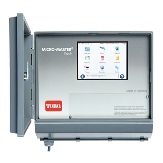
Page 43: Home Screen
Pressing this icon displays the programs list to edit and control programs. Stations Pressing this icon displays the stations list to edit and control stations. Pumps Pressing this icon displays the pump set list to edit and control pump sets. © 2014 Toro Australia Pty Ltd Ver 1.2, June 2014... - Page 44 Pressing this icon displays a help screen explaining the options available from the Home Screen. Irrigation Status Pressing this icon displays the current status of running programs and other controller subsystems. © 2014 Toro Australia Pty Ltd Ver 1.2, June 2014...
-
Page 45: Status Screen
53 seconds remaining. The filter pressure differential switch input is closed, and Filter Bank 1 is active. The 'Next Programs to Start' list show that the Circulation program will commence on Saturday at 1:00am © 2014 Toro Australia Pty Ltd Ver 1.2, June 2014... -
Page 46: Multi Station Programs
After all cycles have completed, the program stops the pump set and filter bank, starts the next program is one has been set, and enters the Idle state, ready to run the process again when required. The Irrigation Program operation is shown in Figure 23. © 2014 Toro Australia Pty Ltd Ver 1.2, June 2014... - Page 47 UNHOLD HOLD Irrigation Held Change Group Group Runtime expired Holding - turn off valves in current group InterGroup Delay Figure 23 - Multi Station Irrigation Program Schematic © 2014 Toro Australia Pty Ltd Ver 1.2, June 2014...
- Page 48 Units for chemical injection can be either hours:minutes, minutes:seconds, or volumetric. If the selected Injection Unit is volumetric, the actual units used are the same as the units for the flow meter allocated to the chemical. © 2014 Toro Australia Pty Ltd Ver 1.2, June 2014...
- Page 49 If a Cycle Delay is set, and the irrigation requires more than 1 cycle, a delay is inserted between the conclusion of the last station group and the commencement of the first station group in the next © 2014 Toro Australia Pty Ltd Ver 1.2, June 2014...
- Page 50 Filter Bank Each program can have it's own Filter Bank. Flow Meter Each program can have it's own Flow Meter. © 2014 Toro Australia Pty Ltd Ver 1.2, June 2014...
-
Page 51: Program Edit Screens
Indicates a Program is empty or is disabled. An empty Program displays "** Empty **", a disabled Program displays the name of the Program. Indicates a Program is enabled but is idle (not running). Indicates a Program is running. © 2014 Toro Australia Pty Ltd Ver 1.2, June 2014... -
Page 52: Program Edit - Sequential
In the example screen shown in Figure 25, Stations 1 to 4 will operate for 1 minute each. In this example, this program has been designed to test each valve individually as a maintenance operation. © 2014 Toro Australia Pty Ltd Ver 1.2, June 2014... - Page 53 Program Enabled Programs can be enabled or disabled. The icon shows the current enabled state of the Program. Clicking on the tick (cross) will change the Program to disabled (enabled). © 2014 Toro Australia Pty Ltd Ver 1.2, June 2014...
-
Page 54: Program Edit - Grouping
The runtimes for each group in the program. Selecting the button and clicking Edit will display the Time Edit screen. Group Stations The stations assigned to each group in the program. Selecting the button and clicking Edit will © 2014 Toro Australia Pty Ltd Ver 1.2, June 2014... -
Page 55: Chemical Edit
Edit will display the Chemical Selection screen. Chemical Runtime The runtime for this chemical for this program group. Selecting the button and clicking Edit will © 2014 Toro Australia Pty Ltd Ver 1.2, June 2014... -
Page 56: Irrigation, Cycles And Start Times
Irrigation cycles are based on a 14 day cycle. Selecting Week 1 or Week 2 displays the irrigation action and cycles for Week 1 or Week 2. Note that Start Times are identical for both Week 1 and Week 2. © 2014 Toro Australia Pty Ltd Ver 1.2, June 2014... -
Page 57: Program Mode And Units
The program mode for this program. Selecting the button and clicking Edit will change the mode between Grouping and Sequential. Irrigation Units The units of irrigation for this program. Selecting the button and clicking Edit will cycle the Irrigation © 2014 Toro Australia Pty Ltd Ver 1.2, June 2014... -
Page 58: Program Delays
Clicking on a delay will select the item, changing the background of the item to light blue. Selecting the button and then clicking Edit will display the Number Edit screen. © 2014 Toro Australia Pty Ltd Ver 1.2, June 2014... -
Page 59: Control Inputs
Clicking on a control sensor will select the item, changing the background of the item to light blue. Selecting the button and then clicking Edit will display the Control Select screen. © 2014 Toro Australia Pty Ltd Ver 1.2, June 2014... -
Page 60: Pumps, Filters And Flow Meters
Programs can be set to ignore the global rain switch setting. This would be the case if a program is used to control non-irrigation equipment. The icon shows the current state of the setting. Clicking on the tick (cross) will change the setting to disabled (enabled). © 2014 Toro Australia Pty Ltd Ver 1.2, June 2014... -
Page 61: Program Status And Totals
This section shows the current status for the selected program including remaining runtime for the current program state. Program Totals This section shows the current totals for the program. Clicking the clear button will clear the totals. © 2014 Toro Australia Pty Ltd Ver 1.2, June 2014... -
Page 62: Single Station Programs
Stopping Active Input Hold on Hold on Hold Hold Input Hold on Held by Held by Input Key Hold on Figure 34 - Single Station Operation Schematic © 2014 Toro Australia Pty Ltd Ver 1.2, June 2014... - Page 63 An allocated Hold Sensor will pause the Station program when the sensor is closed or triggered. A Hold Sensor could be a Switch Input, Digital Input, Analogue Input, Flow Meter or Rule. © 2014 Toro Australia Pty Ltd Ver 1.2, June 2014...
-
Page 64: Station List
This option sets the Station to ignore any Global Water Budget Adjustment commands. 10.2 Station List The Station List screen is displayed by pressing the icon on the Home Screen. Figure 35 - Station Program List © 2014 Toro Australia Pty Ltd Ver 1.2, June 2014... - Page 65 Station Hold Pressing this icon in the action area will hold the selected station if it is running. If the station is currently held, pressing this icon will resume station operation. © 2014 Toro Australia Pty Ltd Ver 1.2, June 2014...
-
Page 66: Station Edit
The runtime for this Station. Selecting the button and clicking Edit will display the Time Edit screen. Station Enabled Stations can be enabled or disabled. Clicking on the tick (cross) will change the Station to disabled (enabled). © 2014 Toro Australia Pty Ltd Ver 1.2, June 2014... -
Page 67: Station Advanced Parameters
Clicking on Next Program will select the item, changing the background of the item to light blue. Selecting the button and then clicking Edit will display the Program and Station Selection screen. © 2014 Toro Australia Pty Ltd Ver 1.2, June 2014... - Page 68 Clicking on Cycle Delay will select the item, changing the background of the item to light blue. Selecting the button and then clicking Edit will display the Number Edit screen. © 2014 Toro Australia Pty Ltd Ver 1.2, June 2014...
- Page 69 Clicking on Hold Sensor will select the item, changing the background of the item to light blue. Selecting the button and then clicking Edit will display the Control Selection screen. © 2014 Toro Australia Pty Ltd Ver 1.2, June 2014...
- Page 70 Clicking on the tick (cross) will change the option to disabled (enabled). Station Status and Totals The Status and Totals screen is the fifth page of Advanced Station Parameters and is displayed by © 2014 Toro Australia Pty Ltd Ver 1.2, June 2014...
- Page 71 This section shows the current status of the station and remaining run or delay time, depending on the current station status. Station Totals This section shows the totals for the Station. Clicking the clear button will clear the totals. © 2014 Toro Australia Pty Ltd Ver 1.2, June 2014...
-
Page 72: Pump Sets
The pump set operation is shown in Figure 42. DelayOn Program Delay Start Complete Idle Active Delay Program Complete Stop DelayOff Figure 42 - Pump Set Operation Schematic © 2014 Toro Australia Pty Ltd Ver 1.2, June 2014... - Page 73 Flow Meter is allocated, all enabled pumps will operate according to the pump set parameters. The allocated Flow Meter can be either a Flow Meter or an Aggregate Flow Meter. © 2014 Toro Australia Pty Ltd Ver 1.2, June 2014...
-
Page 74: Pump Set List
Indicates a Pump Set is empty or is disabled. An empty Pump Set displays "** Empty **", a disabled Pump Set displays the name of the Pump Set. Indicates a Pump Set is not operating. Indicates a Pump Set is operating. © 2014 Toro Australia Pty Ltd Ver 1.2, June 2014... -
Page 75: Pump Set Edit
Clicking on a pump station capacity will select the capacity, changing the background of the selected item to light blue. Selecting a capacity and then clicking Edit will display the Number Edit screen. © 2014 Toro Australia Pty Ltd Ver 1.2, June 2014... -
Page 76: Pump Set Advanced Parameters
Clicking on a pump delay item will select the item, changing the background of the selected item to light blue. Selecting an item and then clicking Edit will display the Number Edit screen. © 2014 Toro Australia Pty Ltd Ver 1.2, June 2014... - Page 77 Clicking on Flow Meter Delay will select the item, changing the background of the item to light blue. Selecting the Flow Meter Delay and then clicking Edit will display the Number Edit screen. © 2014 Toro Australia Pty Ltd Ver 1.2, June 2014...
- Page 78 Pump Set Totals This section shows the current status of each individual pump in the pump set and the totals for each pump. Clicking the clear button will clear the totals. © 2014 Toro Australia Pty Ltd Ver 1.2, June 2014...
-
Page 79: Filter Banks
The filter bank operation is shown in Figure 48. Initial Delay Delay Complete Program Start Idle Backup Delay Delay Complete PD Close or Delay Complete Program Stop Active Filter Delay Complete Figure 48 - Filter Bank Operation Schematic © 2014 Toro Australia Pty Ltd Ver 1.2, June 2014... - Page 80 0 to 99 seconds may be entered. This allows time for the system to stabilize before back-flushing the next filter. The interaction between the delays described above is shown in the next diagram. © 2014 Toro Australia Pty Ltd Ver 1.2, June 2014...
-
Page 81: Filter Bank List
Filter Bank. Clicking on a name will select the Filter Bank, changing the background of the selected Filter Bank to light blue. Selecting a Filter Bank and then clicking Edit will display the Filter Bank Edit screen. © 2014 Toro Australia Pty Ltd Ver 1.2, June 2014... -
Page 82: Filter Bank Edit
Edit will display the Text Edit screen. Filter Station Output Clicking on a filter station item will select the station, changing the background of the selected item to © 2014 Toro Australia Pty Ltd Ver 1.2, June 2014... -
Page 83: Filter Bank Advanced Parameters
If a Filter PD input does not occur for 120 minutes during a single irrigation, a filter cycle will commence. This prevents filter clogging due to faulty PD switches. © 2014 Toro Australia Pty Ltd Ver 1.2, June 2014... - Page 84 This section shows the current status of the filters and remaining run or delay time, depending on the current filter bank status. Filter Bank Totals This section shows the current totals for each individual filter in the filter set. Clicking the clear button will clear the totals. © 2014 Toro Australia Pty Ltd Ver 1.2, June 2014...
-
Page 85: Chemicals
The chemical injection operation is shown in Figure 54. Prewet Delay Delay Start Complete Program Hold Finish Idle Active Held Program Unhold Figure 54 - Chemical Injection Operation Schematic © 2014 Toro Australia Pty Ltd Ver 1.2, June 2014... - Page 86 Allocated Flow Meter The allocated Flow Meter can be either a Flow Meter or an Aggregate Flow Meter. The allocated flow meter can be the same flow meter as the irrigation program. © 2014 Toro Australia Pty Ltd Ver 1.2, June 2014...
-
Page 87: Chemical List
Indicates a Chemical is idle. A Chemical is idle when the Chemical conditions have not been met. Indicates a Chemical is active. A Chemical is triggered when the Chemical conditions have been met. © 2014 Toro Australia Pty Ltd Ver 1.2, June 2014... -
Page 88: Chemical Edit
Selecting an item and then clicking Edit will display the Number Edit or Allocated Station screen. Allocated Flow Meter Clicking on Allocated Flow Meter will select the item, changing the background of the item to light © 2014 Toro Australia Pty Ltd Ver 1.2, June 2014... -
Page 89: Chemical Advanced Parameters
This section shows the current status of the Chemical Injection. Chemical Injection Totals This section shows the current totals for the Chemical Injection. Clicking the clear button will clear the totals. © 2014 Toro Australia Pty Ltd Ver 1.2, June 2014... -
Page 90: Control Sensors
A triggered rule can be used as a control input start, reset, hold, or skip any program or station. Rules can also be used to control various system parameters. © 2014 Toro Australia Pty Ltd Ver 1.2, June 2014... -
Page 91: Sensor Selection
Pressing this icon displays the Aggregate Flow Meter list to edit and control Aggregate Flow Meters. Rain Bucket Pressing this icon displays the Rain Bucket Edit screen to edit and control the Rain Bucket Sensor. © 2014 Toro Australia Pty Ltd Ver 1.2, June 2014... -
Page 92: Rules
When any one of the input control sensor conditions are not met, the rule becomes idle, or untriggered. The rule operation is shown in Figure 59. rule conditions met Active / Idle Triggered rule conditions not met Figure 59 - Rule Operation Schematic © 2014 Toro Australia Pty Ltd Ver 1.2, June 2014... - Page 93 In this scenario, Rule 1 would be "If Sensor 1 IS True AND Sensor 2 IS False". Rule 2 would be "If Rule 1 IS True OR Sensor 3 IS True, START Heat Program" © 2014 Toro Australia Pty Ltd Ver 1.2, June 2014...
-
Page 94: Rules List
Indicates a rule is idle. A rule is idle when the input conditions have not been met. Indicates a rule is triggered. A rule is triggered when the rule conditions have been met. © 2014 Toro Australia Pty Ltd Ver 1.2, June 2014... -
Page 95: Rules Edit
Selecting the item and clicking Edit will change the option from AND to OR or from T(rue) to F(alse) as appropriate. © 2014 Toro Australia Pty Ltd Ver 1.2, June 2014... -
Page 96: Rule Status And Totals
1 or more pulses per litre, 10 litres, 100 litres or kilolitres. Each flow meter can be named and can be enabled or disabled without modifying the inputs. © 2014 Toro Australia Pty Ltd Ver 1.2, June 2014... - Page 97 Flow Meter has a specified output of 1 pulse per 100 litres, the Flow Meter Units could be set to 'Kilolitres', and the Flow Meter Calibration could be set to 10. This may assist in setting runtime units for volumetric programs. © 2014 Toro Australia Pty Ltd Ver 1.2, June 2014...
- Page 98 Note that the total flow and current flow rate use the current saved values for the flow meter. For example, if the calibration value is changed, the change will not be reflected in the total flow or current flow rate until the accept button is pressed. © 2014 Toro Australia Pty Ltd Ver 1.2, June 2014...
-
Page 99: Flow Meter List
Indicates a Flow Meter is active. A Flow Meter is active when flow is detected. Indicates a Flow Meter is triggered. A Flow Meter is triggered when the flow is greater than the trigger level set in the Flow Meter Edit screen. © 2014 Toro Australia Pty Ltd Ver 1.2, June 2014... -
Page 100: Flow Meter Edit
Average This setting adjusts the number of samples over which the flow meter averages the current flow. Selecting the average button and clicking Edit will display the Number Edit screen. © 2014 Toro Australia Pty Ltd Ver 1.2, June 2014... - Page 101 Edit will display the Number Edit screen. Flow Meter Enabled Flow Meters can be enabled or disabled. Clicking on the tick (cross) will change the Flow Meter to disabled (enabled). © 2014 Toro Australia Pty Ltd Ver 1.2, June 2014...
-
Page 102: Flow Meter Status And Totals
Flow meter 2 could be 1 pulse per kilolitre. For the purpose of volumetric flow programs, aggregate flow meter units are always kilolitres, regardless of the flow units for individual input flow meters. © 2014 Toro Australia Pty Ltd Ver 1.2, June 2014... - Page 103 For example, if input flow meter 2 is changed from an addition to subtraction, the change will not be reflected in the total flow or current flow rate until the accept button is pressed. © 2014 Toro Australia Pty Ltd Ver 1.2, June 2014...
-
Page 104: Aggregate Flow Meter List
Indicates an Aggregate Flow Meter is triggered. An Aggregate Flow Meter is triggered when the flow is greater than the trigger level set in the Aggregate Flow Meter Edit screen. © 2014 Toro Australia Pty Ltd Ver 1.2, June 2014... -
Page 105: Aggregate Flow Meter Edit
Add / Subtract Each input flow meter can be added or subtracted from the current flow rate and total flow. Clicking on the plus (minus) will change the setting to subtraction (addition). © 2014 Toro Australia Pty Ltd Ver 1.2, June 2014... -
Page 106: Aggregate Status And Totals
This section shows the current status of the aggregate flow meter. Aggregate Flow Meter Totals This section shows the current totals for the aggregate flow meter. Clicking the clear button will clear the totals. © 2014 Toro Australia Pty Ltd Ver 1.2, June 2014... -
Page 107: Digital Sensors
This scan delay is used to allow time for systems to stabilise after a change in conditions. Depending on the configuration of the irrigation system, the system may need a period of time to stabilise after initial start-up, mainline filling, air evacuation etc. © 2014 Toro Australia Pty Ltd Ver 1.2, June 2014... -
Page 108: Digital List
Indicates a Digital is idle. A Digital is idle when the digital input is open. Indicates a Digital is active. A Digital is active when the digital input is closed. © 2014 Toro Australia Pty Ltd Ver 1.2, June 2014... -
Page 109: Digital Edit
Digital Inputs can have a scanning delay. Selecting the Scan Delay item and clicking Edit will display the Number Edit screen. Digital Sensor Status This item shows the current position of the digital sensor. The item will show either open or closed. © 2014 Toro Australia Pty Ltd Ver 1.2, June 2014... -
Page 110: Digital Status And Totals
Setup. Programs and Station programs can be set to ignore the rain switches. This allows designated programs to operate irrespective of the rain switch parameters. For example, this may include programs controlling non-irrigation functions, or programs irrigating indoor, or sheltered © 2014 Toro Australia Pty Ltd Ver 1.2, June 2014... - Page 111 This setting allows various tipping buckets to be used and reflects the number of pulses a rain bucket will output for each mm of rain. Rain Days This setting determines the number of days the rainfall total is logged. © 2014 Toro Australia Pty Ltd Ver 1.2, June 2014...
-
Page 112: Rain Bucket Edit
Rain Bucket Name The Rain Bucket can be assigned a name. Names are limited to 20 characters. Selecting the name button and clicking Edit will display the Text Edit screen. © 2014 Toro Australia Pty Ltd Ver 1.2, June 2014... -
Page 113: Analogue Sensors
If the calculated input value exceeds the adjustable trigger value, the analogue sensor is triggered. When the calculated input value falls below the trigger value, the analogue sensor becomes active, or untriggered. When the calculated input value falls below the lower limit, the © 2014 Toro Australia Pty Ltd Ver 1.2, June 2014... - Page 114 An example could be a flow meter sensor used to detect overflow conditions, and to skip or stop a currently irrigating program. © 2014 Toro Australia Pty Ltd Ver 1.2, June 2014...
-
Page 115: Analogue List
Indicates an Analogue Sensor is active. An Analogue Sensor is active when the measured analogue value is not zero. Indicates an Analogue Sensor is triggered. An Analogue Sensor is triggered when © 2014 Toro Australia Pty Ltd Ver 1.2, June 2014... -
Page 116: Analogue Edit
The units for an analogue sensor are primarily for ease of use when viewing analogue values and reports. Selecting the Unit button and clicking Edit will display the Text Edit screen. © 2014 Toro Australia Pty Ltd Ver 1.2, June 2014... - Page 117 Analogue Unit item. Analogue Trigger This item sets the level at which the analogue sensor becomes triggered. Selecting the Trigger item and clicking Edit will display the Number Edit screen. © 2014 Toro Australia Pty Ltd Ver 1.2, June 2014...
-
Page 118: Analogue Status And Totals
(or flow switch) installed in the system mainline. In the event of a valve not opening (high pressure and no flow) or a pipeline rupture (low pressure and high © 2014 Toro Australia Pty Ltd Ver 1.2, June 2014... - Page 119 The initial delay is the delay time used only at initial irrigation start, group change, or hold. Scan Delay The scan delay is the delay time used during operational scanning. © 2014 Toro Australia Pty Ltd Ver 1.2, June 2014...
-
Page 120: Switch Sensor List
Input displays the name of the Input. Indicates a Input is idle. A Input is idle when the input is open. Indicates a Input is active. A Input is active when the input is closed. © 2014 Toro Australia Pty Ltd Ver 1.2, June 2014... -
Page 121: Switch Sensor Edit
Edit will display the Number Edit screen. Switch Sensor Enabled Inputs can be enabled or disabled. Clicking on the tick (cross) will change the Input to disabled (enabled). © 2014 Toro Australia Pty Ltd Ver 1.2, June 2014... -
Page 122: Switch Input Status And Totals
This section shows the current status of the Switch Sensors. Switch Sensor Totals This section shows the current totals for the Switch Sensors. Clicking the clear button will clear the totals. © 2014 Toro Australia Pty Ltd Ver 1.2, June 2014... -
Page 123: Manual Spot Watering
Walk-through commences when the start button is pressed. 15.2 Manual Operation The Manual Operation screen is displayed by pressing the icon on the Home Screen. Figure 85 - Manual Operation Screen, Spot Watering © 2014 Toro Australia Pty Ltd Ver 1.2, June 2014... - Page 124 Pump Set If required, a Pump Set can be assigned for the Spot Watering operation. Selecting the Pump Set button and clicking Edit will display the Control Selection screen. © 2014 Toro Australia Pty Ltd Ver 1.2, June 2014...
- Page 125 Manual Operation Skip When operating in walk through mode, this icon skips the current station and commences irrigation with the next station. © 2014 Toro Australia Pty Ltd Ver 1.2, June 2014...
-
Page 126: Reports
Home Screen. Figure 87 - Report Selection Irrigation Reports and Logs Pressing this icon displays the Irrigation Reports list to allow edit and control of Irrigation Reports. © 2014 Toro Australia Pty Ltd Ver 1.2, June 2014... -
Page 127: Report List
Each line in this list displays one item from the Reports and Logs for the selected category. Report and Log Page Selection Clicking a page selection button will display the eight items as listed under the button. © 2014 Toro Australia Pty Ltd Ver 1.2, June 2014... -
Page 128: Report Edit
The Report Edit screen is displayed by pressing the icon on a Report List screen. Figure 89 - Report Edit Report Detail Each report can provide detailed information about each report and when it occurred. © 2014 Toro Australia Pty Ltd Ver 1.2, June 2014... -
Page 129: Report Settings
The Report Settings pages are displayed by pressing the icon on the Report List screen and navigating to the desired page by pressing the icons. Figure 90 - Report Setting Pages © 2014 Toro Australia Pty Ltd Ver 1.2, June 2014... - Page 130 Micro-Master Touch User Guide Figure 91 - Report Setting Pages © 2014 Toro Australia Pty Ltd Ver 1.2, June 2014...
-
Page 131: Life Support
Life Support Level 2 on that expansion module. Life Support can be stopped by pressing the pushbutton on the expansion modules while Life Support is operating. © 2014 Toro Australia Pty Ltd Ver 1.2, June 2014... -
Page 132: Life Support Screen
Clicking on the Repeats item will select the item, changing the background of the selected item to light blue. Selecting the item and then clicking Edit will display the Number Edit screen. © 2014 Toro Australia Pty Ltd Ver 1.2, June 2014... - Page 133 Clicking on a Group item will select the runtime, changing the background of the selected item to light blue. Selecting a group item and then clicking Edit will display the Group Edit screen. © 2014 Toro Australia Pty Ltd Ver 1.2, June 2014...
-
Page 134: Generic Edit Screens
This screen allows the modification of a text entry. Text entries are limited to a number of characters depending the entry being changed. 18.2 Number Edit Figure 94 - Number Edit Screen © 2014 Toro Australia Pty Ltd Ver 1.2, June 2014... -
Page 135: Time Edit
The Delete button deletes the last digit in the time. For example, if 4:35 is display, clicking delete will change the time to 0:43. Any digits can be entered during the modification, but only valid times or runtimes are accepted when the Accept button is clicked. © 2014 Toro Australia Pty Ltd Ver 1.2, June 2014... -
Page 136: Group Edit
The allocated station is coloured green. This screen is used when associating a station with pump sets, filter banks, chemicals, flow meters, digital, and analogue inputs. © 2014 Toro Australia Pty Ltd Ver 1.2, June 2014... -
Page 137: Control / Sensor Selection
Clicking a control / sensor type button will display the control/sensors selected. If the range includes more than 5 valid control / sensors, clicking the top or bottom control/sensor type buttons will display more icons in the display action area. © 2014 Toro Australia Pty Ltd Ver 1.2, June 2014... -
Page 138: Log View
This controls zooms out on the log in the value (y) axis. The zoom is centered around the middle point of the value axis. © 2014 Toro Australia Pty Ltd Ver 1.2, June 2014... -
Page 139: Tmr1 Series Remote
Micro-Master Touch User Guide TMR1 Series Remote The Toro Maintenance Remote is designed for convenience and usability. This powerful tool enables a single operator to perform most manual controller operations remotely from the field. The TMR-1 kit includes a long-range, handheld transmitter complete with NiMH batteries and compatible charger. -
Page 140: Technical Specifications
AC Models supplied with " 2-core-and-E " circular cable and a 7.5 Amp three-pin flat-pin plug complying with Fig. 1a of Australian Standard AS 3112. DC Option supplied with 4 way bypass plug to supply external DC power. © 2014 Toro Australia Pty Ltd Ver 1.2, June 2014... - Page 141 Current sensing processor @ approx. 2.0 Amp with Auto-skip turn-off. Standby Battery Type: Miniature 9 Volt alkaline MN1604B. Life: 10 hours standby (nominal). Cabinet Lockable, weather proof. Dimensions: 300 x 220 x 130mm. Mass: 4.3 kg. © 2014 Toro Australia Pty Ltd Ver 1.2, June 2014...
- Page 142 C-Tick Class A, Approval No N13376 E834 *Reference to specific products, services or companies in this publication does not imply endorsement or specific recommendation of any product, service or company. © 2014 Toro Australia Pty Ltd Ver 1.2, June 2014...
-
Page 143: Fault Finding
TDS Software Solutions Pty Ltd Unit 11 / 78 Morrow Rd, Lonsdale South Australia, 5160 Phone: +61 8 8383 6851 Mobile: 0414 645 171 Email: david@tdssoftware.com.au Web: www.tdssoftware.com.au Micro-Master Forum: forum.tdssoftware.com.au © 2014 Toro Australia Pty Ltd Ver 1.2, June 2014... -
Page 144: Fault Finding Flow Chart
Check Sensor is inactive Irrigation Time is Shorter than Auto Skip Fault has occurred Check fault table Programmed Stop Sensor was active Check Sensor Report Program Error Check Runtimes, Water Budget © 2014 Toro Australia Pty Ltd Ver 1.2, June 2014... -
Page 145: Diagnostics
If the Log to USB is enabled and a valid USB Flash Drive is connected to the controller, detailed diagnostic messages will be saved to a file on the USB Flash Drive. If necessary, these diagnostic messages may assist in isolating problems in the controller. © 2014 Toro Australia Pty Ltd Ver 1.2, June 2014... -
Page 146: Checking Field Wiring And Valve Currents
AC current meter with a current range of at least 10 Amps. Note that connecting in series to the valve wiring can be accomplished by connecting in series with the common or return wire. © 2014 Toro Australia Pty Ltd Ver 1.2, June 2014... -
Page 147: Voltage On Unused Pins
240 VAC coil of almost any size. 21.6 Voltage On Unused Pins The 24VAC is a floating output. i.e. it does not have any reference to earth. The following readings © 2014 Toro Australia Pty Ltd Ver 1.2, June 2014... - Page 148 When a standard solenoid is connected across these inputs the voltage will be 0VAC. The varistor surge protection devices will change to a very low impedance only under over-voltage surge conditions in excess of 50VAC. © 2014 Toro Australia Pty Ltd Ver 1.2, June 2014...
-
Page 149: Copyright Notice
ON ANY THEORY OF LIABILITY, WHETHER IN CONTRACT, STRICT LIABILITY, OR TORT (INCLUDING NEGLIGENCE OR OTHERWISE) ARISING IN ANY WAY OUT OF THE USE OF THIS SOFTWARE, EVEN IF ADVISED OF THE POSSIBILITY OF SUCH DAMAGE © 2014 Toro Australia Pty Ltd Ver 1.2, June 2014... -
Page 150: Glossary Of Terms
Typical sensors are Pressure, Flow, Water Level etc. SEQUENTIAL Field valves will be switched in sequence ,starting from the valve connected to station 1 and increasing to the last station programmed. © 2014 Toro Australia Pty Ltd Ver 1.2, June 2014... - Page 151 A controller output or terminal to connect a valve to. VALVE OUTPUT Same as station. WATER BUDGET A percentage value that will globally modify the runtime of all station Run times within a program. © 2014 Toro Australia Pty Ltd Ver 1.2, June 2014...
- Page 152 Toro Australia Pty Ltd 53 Howards Road Beverley SA 5009 A.B.N. 47 001 310 443 Customer Service Phone: 1300 130 898 Fax: 08 8234 2940...
Need help?
Do you have a question about the Micro-Master Series and is the answer not in the manual?
Questions and answers