Table of Contents
Advertisement
Advertisement
Table of Contents

Related Manuals for Toro TMC-424


Summary of Contents for Toro TMC-424
- Page 1 TMC-424 ODULAR ONTROLLER 24 S TATIONS User’s Guide...
- Page 2 Introduction Thank you for purchasing a Toro TMC-424 modular series controller. The versatile TMC-424 is easily expanded from 4 to 24 stations with plug-in 4- and 8-station output modules. It’s flexible modular design, coupled with an intuitive, full-feature timing mechanism, makes the TMC-424 controller an ideal choice for residential, commercial and sports field irrigation systems.
-
Page 3: Table Of Contents
Specifications ..........28 The Toro Promise — Limited Five-year Warranty ....29... -
Page 4: Controller Components
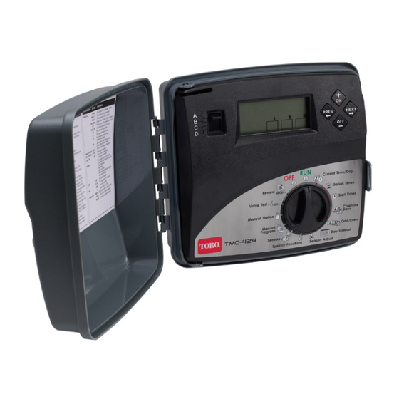
Controller Components The following brief descriptions of the controller components and display elements are provided for general overview. Each of these items will be explained in further detail in the appropriate section of this guide. 1- Service Reset Button 6- Navigation Buttons Facilitates controller CPU initial- Left and right arrow buttons to ization (for service only). - Page 5 VALVE TEST – Enables all sta- MANUAL PROGRAMS – Enables tions to be operated in sequence individual watering programs to for a selected temporary run time be manually started. from 30 seconds to 10 minutes. SENSORS – Enables flow mon- REVIEW –...
- Page 6 Controller Components 8- Plug-in transformer 16- Standard module (4-station, (indoor models only) standard-surge model shown) 9- Power supply compartment 17- Valve connection terminals cover (outdoor models only) 18- Power source connection 10- Control panel cable receptacle terminals (outdoor models only) 11- Plug-in transformer connection 19- Wire connection terminals for: terminals (indoor models only)
-
Page 7: Getting Started
In basic terms, a watering program is a small set of instructions that tells the controller which days will be active for watering, when to start a watering cycle, and how long each station will operate during the cycle. The TMC-424 series has four independent watering programs identified as A, B, C, and D. -
Page 8: Set Current Time And Date
Programming the Controller Note: English display prompts and 12-hour (a.m./p.m.) time format are default control module interface settings. To select Spanish, French, Italian or German as the display language, and/or a 24-hour time format, refer to the Special Functions information page 9. Set Current Time and Date 1. -
Page 9: Set Program Start Time
Set Program Start Time Note:The TMC-424 provides a total of 16 watering cycle start time slots to be allocated among the four programs in any combination. 1. Turn the Function Dial to the Set Start Times position. 2. Press the buttons to select a start time slot number from 01 to 16. - Page 10 Note: Each program can only have one assigned watering schedule format. If either an Interval or Odd/Even schedule is currently set, it must be turned off first to enable another format to be selected. To Set Calendar Days: 1. Turn the Function Dial to the Calendar Days position.
-
Page 11: Special Functions
Special Functions The following operating and control options enable you to taylor the TMC-424 user interface and operating characteristics to suit the specific needs of the landscape and irrigation system. When the Function Dial is turned to the Special Functions... -
Page 12: Program Stacking/Sequential Operation
• Setting Master Valve/Pump Start Operation The factory default for the Master Valve/Pump Start (MV/PS) is On for all programs and stations. The TMC-424 allows you to disable MV/PS operation by specific program(s) and specific station(s). Note: The TMC-424 has one standard Master Valve/Pump Start (MV/PS) connection terminal. -
Page 13: Pump Start /Master Valve Operation By Station
MV/PS operation enabled remain displayed. • Display Language Options The TMC-424 displays word prompts in English (ENG) by default and offers four additional languages options as follows: Spanish (ESP), French (FRA), Italian (ITA) and German (DEU) 1. -
Page 14: Manual Operations
Manual Operations There are several methods by which the TMC-424 can be operated manually. A separate Function Dial position is provided for Manual Stations operation and Manual Programs operation. Manual Operations by Station The TMC-424 offers two ways to manually activate individual stations. The first method, called "True Manual"... -
Page 15: Manual Operations By Program
Manual Operations by Program This type of manual watering is also known as “Semi-automatic” operation. When a program is started manually, it runs through the watering cycle as if it had been started automatically. A single program can be selected and started or multiple programs can be selected to run in sequence. -
Page 16: Flow Sensor Operation
The TMC-424 accepts up to three Flow Sensor modules that enable it to read, store and compare flow rate data from individual flow meters. - Page 17 7. Repeat step 5 and 6 for each flow sensor module installed. The flow meter icon indicates the module being addressed. button to display NF -- -- (Nominal Flow). This is the measured 8. Press the flow rate when no stations are operating. This setting triggers an alarm when flow ranging from 1 to 99 PPS (pulses per second) is detected while the controller is idle.
-
Page 18: Rain Sensor Timed Bypass Function
Rain Sensor Timed Bypass Rain sensor operation is manually controlled by the bypass switch (see item 14 on page 4). The TMC-424 has a unique feature called “Timed Bypass” that bypasses any rain sensor input and overrides the rain sensor switch regardless of it’s set position. -
Page 19: Valve Test Function
Valve Test Function This feature allows you to quickly step through the operation of each station for initial installation check, periodic maintenance, spring start-up etc. The preset time for each station is two minutes but can be quickly adjusted from 30 seconds to 10 minutes. -
Page 20: Rain Delay Function
Rain Delay Function Note: The Rain Delay and Water Budget control features enable quick, temporary changes in operation to help compensate for changes in weather and season. Rain Delay enables all automatic watering operations to be delayed from 1 to 14 days. For example, rain is forecast in your area for the next two days. Instead of turning the controller off and possibly forgetting to turn it back on, a 3-day delay can be easily set. -
Page 21: Installation Instructions
B- Two 1/2" (13mm) (plugged) for the optional wiring connections. C- Two 3/4" or 1" (19mm or 26mm) for valve and pump relay wiring. 4. If planning to install the optional Toro components, remove the access plugs as necessary. Note: Conduit and adapters are not provided. Always install conduit as... - Page 22 Cabinet Installation 1. Indoor Models – Select a location for the controller within 4' (1.2m) of an elec- trical outlet to enable the transformer wires to easily reach. Make sure the out- let is not controlled by a light switch or utilized to power a major appliance. Outdoor Models –...
- Page 23 station it controls. You will need to have this information available when connecting the valve wires to the controller. 4. Secure all wire splices using twist-on wire connectors. To prevent corrosion and possible short circuits, use a grease cap or similar waterproofing method to insulate each connection.
- Page 24 3. If the master valve circuit is used, connect either valve wire to the MV terminal and the remaining wire to either common (C) terminal. Note: During operation, the the control module’s master valve is active only when a station assigned to the master valve is operating. Power Connection - Indoor Models North American Models 1.
- Page 25 (not provided) to facil- itate an earth ground connection may be recommended. Refer to the inset detail shown below for suggested installation method. Contact an authorized Toro representative for specific grounding recommendations in your region. Earth Ground Connection (optional)
- Page 26 When the sensor absorbs moisture or detects a near-freezing temperature, it signals the TMC-424 to suspend automatic watering operations. SEN will be displayed until the sensor automatically resets enabling the controller to return to automatic operation.
-
Page 27: Appendix
Appendix Table 1 Data Industrial 228/250 Series Flow Sensor Data Converting PPS to GPM/LPM The flow meter measures water flow in PPS (Pulses per Second). To convert PPS to GPM (Gallons per Minute) or LPM (Liters per Minute), use the following formula: To convert PPS to GPM: K x (F + Offset) = GPM... - Page 28 Determining Maximum Current Load Table 2 above provides various current load combinations that are possible when using 1, 2 or 3 watering programs running simultaneously with master valve/pump start control options. Table 2 Output Current Load Reference cceptable Marginal Exceeds Limit The values in the Station Valve row indicate the number of solenoid loads based on one station/valve per program.
-
Page 29: Troubleshooting
Troubleshooting Fuse – Electronic Circuit Breaker The TMC-424 features built-in circuit protection to help prevent damage to the controller caused by excessive current draw on the station and/or pump/master valve circuits. If the controller detects an overload condition, it will bypass the affected station(s). -
Page 30: Specifications
Specifications Cabinet Dimensions: 10.5" W x 9.5" H x 5" D Temperature Limit Range: Operating: +14°F to +140°F (-10°C to +60°C) Storage: -22°F to +149°F (-30°C to +65°C) Power Specifications: Indoor Model - North America Plug-in Transformer, Class 2, UL Listed, CSA-certified •... -
Page 31: The Toro Promise - Limited Five-Year Warranty
Your remedy is limited solely to the replacement or repair of defective parts. Return the defective part to your local Toro distributor, who may be listed in your telephone directory Yellow Pages under "Irrigation Supplies" or "Sprinkler Systems,"... -
Page 32: Fcc Compliance Information
FCC Compliance Information This equipment generates and uses radio frequency energy and if not installed and used properly, that is, in strict accordance with the manufacturer’s instruc- tions, may cause interference to radio and television reception. It has been type tested and found to comply with the limits for a FCC Class B computing device in accordance with the specifications in Subpart J of Part 15 of FCC Rules, which are designed to provide reasonable protection against such interference...
Need help?
Do you have a question about the TMC-424 and is the answer not in the manual?
Questions and answers
The display disappears after 15 seconds after reset toro system not working.
The display on a Toro TMC-424 system could disappear after 15 seconds if there is no 24-volt power supply connected and only a 9-volt battery is installed. The 9-volt battery only saves the time and date but cannot power the system.
This answer is automatically generated