
Related Manuals for DFI PL610-C622


Summary of Contents for DFI PL610-C622
- Page 1 PL610-C622 ATX Industrial Motherboard User’s Manual Preliminary Version A48100840...
-
Page 2: Copyright
Copyright FCC and DOC Statement on Class B This publication contains information that is protected by copyright. No part of it may be re- This equipment has been tested and found to comply with the limits for a Class B digital produced in any form or by any means or used to make any transformation/adaptation without device, pursuant to Part 15 of the FCC rules. -
Page 3: Table Of Contents
Table of Contents Power Connectors ..............21 Front Panel Connector .............. 22 LEDs ..................23 Copyright .......... 2 Expansion Slots ............... 23 PLD Update Connector .............. 24 Battery ................... 24 Trademarks ........2 SMBus Connector ..............25 COM (Serial) Ports ..............25 LPC Debug Connector ............... -
Page 4: Warranty
Warranty Static Electricity Precautions 1. Warranty does not cover damages or failures that arised from misuse of the product, It is quite easy to inadvertently damage your PC, system board, components or devices even inability to use the product, unauthorized replacement or alteration of components and before installing them in your system unit. -
Page 5: About The Package
The package contains the following items. If any of these items are missing or damaged, please contact your dealer or sales representative for assistance. • One PL610-C622 motherboard • One COM port cable (Length: 400mm, 2 x COM ports) •... -
Page 6: Chapter 1 - Introduction
Chapter 1 Chapter 1 - Introduction Specifications SYSTEM Processor Intel Xeon Scalable Processor Family, LGA 3647 Socket INTERNAL I/O Serial 1 x RS-232 (2.54mm pitch) ® ® Chipset Intel C622 Chipset ® 2 x USB 2.0 (2.54mm pitch) 1 x Vertical USB 2.0 Memory Six 288-pin RDIMM up to 192GB 2 x USB 3.0... -
Page 7: Features
Chapter 1 • Wake-On-LAN Features This feature allows the network to remotely wake up a Soft Power Down (Soft-Off) PC. It • Watchdog Timer is supported via the onboard LAN port or via a PCI LAN card that uses the PCI PME (Power Management Event) signal. - Page 8 Chapter 1 • Power Failure Recovery When power returns after an AC power failure, you may choose to either power-on the system manually or let the system power-on automatically. • USB The system board supports the new USB 3.0. It is capable of running at a maximum transmis- sion speed of up to 5 Gbit/s (625 MB/s) and is faster than USB 2.0 (480 Mbit/s, or 60 MB/s) and USB 1.1 (12Mb/s).
-
Page 9: Chapter 2 - Hardware Installation
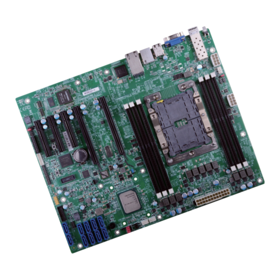
Chapter 2 Chapter 2 - Hardware Installation Important: Board Layout Electrostatic discharge (ESD) can damage your board, processor, disk drives, add-in boards, and other components. Perform installation procedures at an ESD workstation +12V only. If such a station is not available, you can provide some ESD protection by wear- Power ing an antistatic wrist strap and attaching it to a metal part of the system chassis. -
Page 10: Installing The Dimm Module
Chapter 2 The system board supports the following memory interface. Installing the DIMM Module Single Channel (SC) Note: The system board used in the following illustrations may not resemble the actual Data will be accessed in chunks of 64 bits (8B) from the memory channels. board. -
Page 11: Cpu
Chapter 2 6. Grasping the module by its edges, position the module above the socket with the “notch” in the module aligned with the “key” on the socket. The keying mechanism ensures the module can be plugged into the socket in only one way. The system board is equipped with a surface mount LGA 3647 socket. -
Page 12: Installing The Cpu, Fan And Heat Sink
Chapter 2 Installing the CPU, Fan and Heat Sink 3. Place the CPU carrier on Mounting hole #1 of top of the heat sink. Place the heat sink the triangular hole near The CPU must be kept cool by using a CPU fan with heat sink. Without sufficient air circula- the mounting hole #1 of tion across the CPU and heat sink, the CPU will overheat damaging both the CPU and system the heat sink. - Page 13 Chapter 2 5. Place the fan / heat sink assembly on top of the socket. Use the T30 screwdriver to install the assembly according to the sequence of the screws shown on the label. 6. Connect the CPU fan’s cable to the CPU fan connector on the system board.
-
Page 14: Jumper Settings
Chapter 2 Jumper Settings Clear CMOS BMC/PCH SMB Host Select 1-2 On: BMC SMB Host (default) 1-2 On: Normal (default) JP16 Battery Battery JP15 2-3 On: PCH SMB Host 2-3 On: Clear RTC Registers JP16 is used to select SMB host: BMC or PCH. If you encounter the followings, a) CMOS data becomes corrupted. -
Page 15: Flash Security Override
Chapter 2 Flash Security Override PCIe 3 Switch 1-2 On: Riser 3 (default) 1-2 On: Disable (default) JP14 Battery Battery 2-3 On: 2-3 On: Enable JP8 is used to enable or disable flash security override. JP14 is used to select PCIe 3: Riser 3 or 10G. When JP14 is set to 1-2 on and “On board 10G LAN”... -
Page 16: Enable Espi
Chapter 2 Enable eSPI UART Debug Select 0 On: 0 On: UART1 as LPC Mode (default) BMC Console Port (default) Battery Battery 1 On: 1 On: UART5 as eSPI Mode BMC Console Port J14 is used to enable eSPI or LPC mode. JP2 is used to select UART1 or UART5 as BMC Console Port. -
Page 17: Rear Panel I/O Ports
Chapter 2 Rear Panel I/O Ports Graphics Interface The display port consists of the following: • 1 VGA port 10GLAN USB 2.0 GLAN The rear panel I/O ports consist of the following: • 1 10GLAN • 1 VGA port • 2 USB 2.0 ports •... -
Page 18: Lan Ports
Chapter 2 USB Ports LAN Ports 10GLAN USB 2 USB 1 USB 2.0 GLAN Battery Battery USB 3 USB 4-5 USB 5-6 Features USB 2.0 • 1 i350-AM2 • 1 CS4227 USB 3.0 • 1 RTL8211F USB 2.0 The LAN port allows the system board to connect to a local area network by means of a The USB device allows data exchange between your computer and a wide range of simultane- network hub. - Page 19 Chapter 2 Driver Installation You may need to install the proper drivers in your system operation to use the USB device. Re- fer to your operating system’s manual or documentation for more information. Wake-On-USB Keyboard/Mouse The Wake-On-USB Keyboard/Mouse function allows you to use a USB keyboard or USB mouse to wake up a system from the S3 (STR - Suspend To RAM) state.
-
Page 20: I/O Connectors
Chapter 2 I/O Connectors BMC JTAG Female Header SATA (Serial ATA) Connectors Battery Battery SATA 1 SATA 0 BMC JTAG SATA 3 SATA 2 SATA 5 SATA 4 Features Pin Assignment Pin Assignment • 6 Serial ATA 3.0 ports with data transfer rate up to 6Gb/s 3V3SB 3V3SB •... -
Page 21: Cooling Fan Connectors
Chapter 2 Cooling Fan Connectors Power Connectors Ground CPU Fan +12V Power +12V Power Ground Speed +12V Control Power Sense 12 24 Power +3.3V +12V +12V +5VSB PWR_OK Ground System Fan 1 Power System Fan 2 Sense PS_ON# Speed Control Battery Battery +3.3V... -
Page 22: Front Panel Connector
Chapter 2 Front Panel Connector Pin Pin Assignment Pin Pin Assignment LED Power Power CONT STAT GRN PWR-LED Signal Signal HD Power Power HD-LED Signal N.C. Power N.C. CONT STAT AMBER Signal N.C. Ground SMB PWR SEQ DAT 8 RESET BTN RST Signal SMB PWR SEQ CLK 8 Ground... -
Page 23: Leds
Chapter 2 LEDs Expansion Slots PCI Express x16 I350 PE Wake LED Battery Battery PCI Express x16 PCI Express x4 PCI Express x8 PCI Express x4 BMC Heartbeat LED PCI Express x16 Slot CONT Stat GRN LED CONT Stat Amber LED Install PCI Express x16 graphics card, that comply to the PCI Express specifications, into the PCI Express x16 slot. -
Page 24: Pld Update Connector
Chapter 2 PLD Update Battery Battery Battery Battery PLD Update The lithium ion battery powers the real-time clock and CMOS memory. It is an auxiliary source of power when the main power is shut off. Pin Assignment Pin Assignment Safety Measures •... -
Page 25: Smbus Connector
Chapter 2 SMBus Connector COM (Serial) Ports COM Port C from PCH’s IE Battery SPC IE LVC3 RX Battery HSUart SPC IE LVC3 TX SMBus BMC COM 5 The SMBus (System Management Bus) connector is used to connect SMBus devices. It is a BMC TXD5 multiple device bus that allows multiple chips to connect to the same bus and enable each one BMC RXD5... -
Page 26: Lpc Debug Connector
Chapter 2 LPC Debug Connector Switch Battery Battery The Low Pin Count Interface was defined by Intel ® Corporation to facilitate the industry’s tran- BMC Reset Button sition towards legacy free systems. It allows the integration of low-bandwidth legacy I/O com- ponents within the system, which are typically provided by a Super I/O controller. -
Page 27: Phy I2C Sda/Scl 1P8V Debug Connector
Chapter 2 PHY I2C SDA/SCL 1P8V Debug Connector Clock Gen Clock Ref Connector PHY I2C SDA/SCL 1P8V Debug Battery Battery Clock Gen Clock Ref Pin Assignment Pin Assignment SFFP0 EEPROM I2C SCL CLK 100M PE CLKREF P SFFP0 EEPROM I2C SDA CLK 100M PE CLKREF N Chapter 2 Hardware Installation www.dfi... -
Page 28: Chapter 3 - Bios Setup
Chapter 3 Chapter 3 - BIOS Setup Legends Overview Keys Function The BIOS is a program that takes care of the basic level of communication between the CPU and peripherals. It contains codes for various advanced features found in this system board. Right and Left arrows Moves the highlight left or right to select a menu. -
Page 29: Insyde Bios Setup Utility
Chapter 3 Insyde BIOS Setup Utility Advanced Main The Advanced menu allows you to configure your system for basic operation. Some entries are defaults required by the system board, while others, if enabled, will improve the performance of your system or let you set some features according to your preference. The Main menu is the first screen that you will see when you enter the BIOS Setup Utility. - Page 30 Chapter 3 ACPI Configuration Note: Under Dual Boot Type or UEFI Boot Type mode, if Quiet Boot is set to enabled, This section is used to configure the system ACPI parameters. BGRT Logo field will appear for configuration. Refer to the Boot menu for more information.
- Page 31 Chapter 3 CPU Configuration Video Configuration This section is used to configure the CPU. This section configures the video settings. InsydeH2O Setup Utility Rev. 5.0 InsydeH2O Setup Utility Rev. 5.0 Advanced Advanced Set Display Mode Confi g- Video Confi guration ure Type.
- Page 32 Chapter 3 SATA Configuration InsydeH2O Setup Utility Rev. 5.0 Advanced This section is designed to select the SATA controller and the type of hard disk drive which are Enable or Disable SATA installed in your system unit. PCH sSATA Confi guration Controller SATA Controller <Enabled>...
- Page 33 Chapter 3 USB Configuration PCI Express Configuration This section is used to configure the parameters of the USB device. This section configures settings relevant to PCI Express root ports. InsydeH2O Setup Utility Rev. 5.0 Advanced InsydeH2O Setup Utility Rev. 5.0 PCIE port confi...
- Page 34 Chapter 3 Debug Configuration InsydeH2O Setup Utility Rev. 5.0 Advanced This section configures Debug setting. In auto mode the BIOS PCIE1 will remove the EXP port if there is no device or er- Port Enabled <Auto> rors on that device and the InsydeH2O Setup Utility Rev.
- Page 35 Chapter 3 Device Manager EFI debug print level The section configures device with option ROM, such as LAN card, etc. Enter the numeric value for EFI debug print level. The default is 0x8000004F. EFI debug serial port InsydeH2O Setup Utility Rev.
- Page 36 Chapter 3 SIO AST2500 H2O IPMI Configuration This section configures the system super I/O chip parameters. This section configures the H2O IPMI (Intelligent Platform Managment Interface). InsydeH2O Setup Utility Rev. 5.0 Advanced InsydeH2O Setup Utility Advanced Enable/Disable IPMI Sup- IPMI Support <Enabled>...
- Page 37 Chapter 3 BMC Configuration User Configuration This section configures the BMC related settings. InsydeH2O Setup Utility Rev. 5.0 Advanced InsydeH2O Setup Utility Rev. 5.0 This is User ID for BMC, User Confi guration Advanced Set/Get User information User ID according to it. The MAX User Status <Enabled>...
- Page 38 Chapter 3 SDR List Lan Port Configuration This section displays all SDRs information provided by BMC. Select the LAN port access mode: Dedicated or Shared. LAN Channel Number InsydeH2O Setup Utility Rev. 5.0 Advanced Enter the LAN channel number for BMC. The valid LAN channel number is 1, 2, or 3. Disable/Enable list all SDR List SDRs information.
- Page 39 Chapter 3 InsydeH2O Setup Utility Rev. 5.0 InsydeH2O Setup Utility Rev. 5.0 Advanced Advanced ↑ Disable/Enable list all Sensor Number: 0xE0 SDR List PCH Temp SDRs information. Lower Non-Critical BB BMC Temp Threshold: N/A SDR List Support <Enabled> ...
- Page 40 Chapter 3 Execute H2O IPMI Utility Console Redirection This section configures H2O IPMI Utility. Please contact your sales representative for This section configures settings relevant to console redirection. more information. InsydeH2O Setup Utility Rev. 5.0 Advanced Enable Console Redirec- Console Redirection Setup tion Function Console Serial Redirect <Disabled>...
- Page 41 Chapter 3 When Console Serial Redirect is set to enabled, the screen will appear like below: COM_A InsydeH2O Setup Utility Rev. 5.0 InsydeH2O Setup Utility Rev. 5.0 Advanced Advanced Console Redirection Setup Enable Console Redirec- tion Function COM_A Console Serial Redirect <Enabled>...
-
Page 42: Security
Chapter 3 When UseGlobalSetting is set to disabled, the screen will appear like below: Security InsydeH2O Setup Utility Rev. 5.0 InsydeH2O Setup Utility Rev. 5.0 Main Advanced Security Boot Exit Advanced When Hidden, don’t ex- Current TPM Device <TPM 2.0 (DTPM)> poses TPM to 0 PortEnable <Enabled>... -
Page 43: Boot
Chapter 3 Boot PXE Boot to LAN Disable or enable PXE boot to LAN. InsydeH2O Setup Utility Rev. 5.0 Main Advanced Security Boot Exit USB Boot Selects Power-on state for Numlock Numlock <Off> Boot Type <Dual Boot Type> Enable or disable booting to USB boot devices. Network Stack <Disabled>... -
Page 44: Exit
Chapter 3 Updating the BIOS Exit To update the BIOS, you will need the new BIOS file and a flash utility. Please contact techni- cal support or your sales representative for the files. InsydeH2O Setup Utility Rev. 5.0 Main Advanced Security Boot Exit... -
Page 45: Notice: Bios Spi Rom
Chapter 3 Notice: BIOS SPI ROM 1. The Intel Management Engine has already been integrated into this system board. Due to ® the safety concerns, the BIOS (SPI ROM) chip cannot be removed from this system board and used on another system board of the same model. 2. -
Page 46: Chapter 4 - Supported Software
Please download drivers, utilities and software applications required to enhance the perfor- tion tips then click “Install”. mance of the system board at https://www.dfi.com/DownloadCenter . Intel Chipset Software Installation Utility The Intel Chipset Software Installation Utility is used for updating Windows ®... - Page 47 Chapter 4 Intel Graphics Drivers 3. Go through the readme document for system re- quirements and installation To install the driver, download “PL610 Graphics Driver” zip file at our website. tips then click “Next”. 1. Setup is now ready to install the graphics driver.
- Page 48 Chapter 4 Intel LAN Drivers 4. Click “Install” to begin the installation. To install the driver, download “PL610 LAN Driver” zip file at our website. 1. Setup is ready to install the driver. Click “Next”. 5. The step displays the installing status in the prog- ress.
- Page 49 Chapter 4 Adobe Acrobat Reader 9.3 3. Setup is now installing the driver. To install the reader, download “PL610 Driver Package” iso file at our website. Click “Adobe Acrobat Reader 9.3”. 1. Click “Next” to install or click “Change Destination Folder”...
- Page 50 Chapter 4 Intel Rapid Storage Technology 3. Go through the readme document to view system requirements and installa- The Intel Rapid Storage Technology is a utility that allows you to monitor the current status tion information then click of the SATA drives. It enables enhanced performance and power management for the storage “Next”.
- Page 51 Chapter 4 6. Click “Yes, I want to restart this computer now” to complete the installation and then click “Finish”. Chapter 4 Supported Software www.dfi .com...
-
Page 52: Chapter 5 - Raid
Chapter 5 Chapter 5 - RAID Settings The system board allows configuring RAID on Serial ATA drives. It supports RAID 0, RAID 1, RAID 5 and RAID 10. To enable the RAID function, the following settings are required. RAID Levels 1. - Page 53 Chapter 5 Step 3: Create a RAID Volume Step 3-1: Create a RAID Volume if the boot type is UEFI 1. When the Intel RST option ROM status screen displays during POST, press <Ctrl> and If the boot type is set to UEFI, RAID volume creation will be different. Please use the following ®...
- Page 54 Chapter 5 Step 4: Install the Intel Rapid Storage Technology Utility The Intel Rapid Storage Technology Utility can be installed from within Windows. It allows RAID volume management (create, delete, migrate) from within the operating system. It will also display useful SATA device and RAID volume information. The user interface, tray icon service and monitor service allow you to monitor the current status of the RAID volume and/ or SATA drives.
Need help?
Do you have a question about the PL610-C622 and is the answer not in the manual?
Questions and answers