Sign In
Upload
Download
Table of Contents
Contents
Add to my manuals
Delete from my manuals
Share
URL of this page:
HTML Link:
Bookmark this page
Add
Manual will be automatically added to "My Manuals"
Print this page
×
Bookmark added
×
Added to my manuals
Manuals
Brands
DFI Manuals
Motherboard
PS35-BC
User manual
DFI PS35-BC User Manual
Hide thumbs
1
2
3
4
Table Of Contents
5
6
7
8
9
10
11
12
13
14
15
16
17
18
19
20
21
22
23
24
25
26
27
28
29
30
31
32
33
34
35
36
37
38
39
40
41
42
43
44
45
46
47
48
49
50
51
52
53
54
55
56
57
58
59
60
61
62
63
64
65
66
67
68
69
70
71
72
73
74
75
76
77
78
79
80
81
82
83
84
85
86
87
88
89
90
91
92
93
94
95
96
97
98
99
100
101
102
103
104
105
106
107
108
109
110
111
112
113
114
115
116
117
118
119
120
121
122
page
of
122
Go
/
122
Contents
Table of Contents
Troubleshooting
Bookmarks
Table of Contents
Fcc and Doc Statement on Class B
System Board
Table of Contents
Chapter 1 - Introduction
Features and Specifications
Hyper-Threading Technology Functionality Requirements
Package Checklist
Chapter 2 - Hardware Installation
System Board Layout
Hardware Installation
System Memory
Installing the DIM Module
Cpu
Installing the Cpu
Installing the Fan and Heat Sink
Jumper Settings
Rear Panel I/O Ports
Serial Ports
Parallel Port
Vga Port
Universal Serial Bus Ports
I/O Connectors
Floppy Disk Drive Connector
Serial Ata Connectors
Ide Disk Drive Connector
Irda Connector
Cpu Fan Connector
Power Connectors
Front Panel Connectors
Chapter 3 - Award BIOS Setup Utility
The Basic Input/Output System
Standard CMOS Features
Award Bios Setup Utility
Advanced BIOS Features
Advanced Chipset Features
Integrated Peripherals
Power Management Setup
Pnp/Pci Configurations
CPU Frequency Control
Load Fail-Safe Defaults
Load Optimized Defaults
Set Supervisor Password
Set User Password
Save & Exit Setup
Exit Without Saving
Updating the BIOS
Chapter 4 - Supported Softwares
Desktop Management Interface
Supported Software
Using the DMI Utility
Add DMI
Drivers, Utilities and Software Applications
Intel Chipset Software Installation Utility
Intel Graphics Drivers
Audio Drivers
Audio Configuration
Installation Notes
Appendix A - Enabling the Hyper-Threading Technology
Enabling the Hyper-Threading Technology
Appendix B - System Error Messages
POST Beep
Error Messages
Appendix C - Troubleshooting
Troubleshooting Checklist
Power Supply
Floppy Drive
Hard Drive
Serial Port
Advertisement
Quick Links
1
System Board
2
Features and Specifications
3
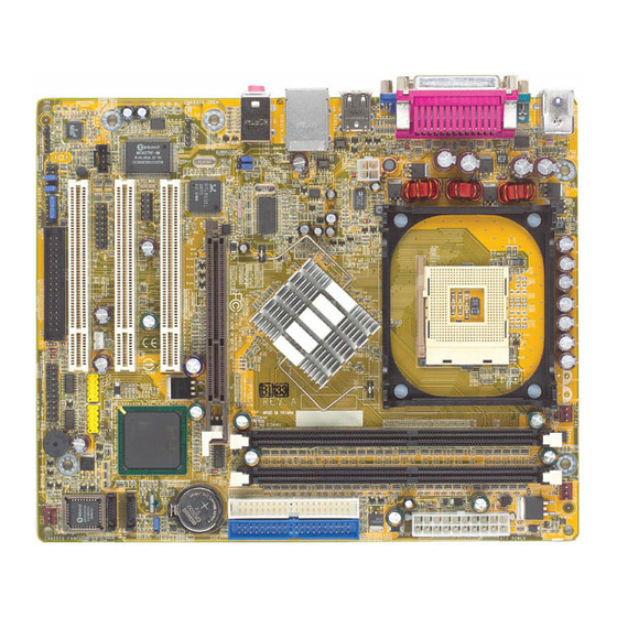
System Board Layout
4
Jumper Settings
5
Front Panel Connectors
6
Post Beep
Download this manual
PS35-BC
PS35-BL
Rev. A+
System Board
User's Manual
72100314
Table of
Contents
Previous
Page
Next
Page
1
2
3
4
5
Advertisement
Table of Contents
Need help?
Do you have a question about the PS35-BC and is the answer not in the manual?
Ask a question
Questions and answers
Related Manuals for DFI PS35-BC
Motherboard DFI PS35-BL User Manual
(122 pages)
Motherboard DFI PS82-BC/BL User Manual
(135 pages)
Motherboard DFI P5BV3+ User Manual
Rev. c+ system board (67 pages)
Motherboard DFI K6XV3+/66 User Manual
(43 pages)
Motherboard DFI P2XBL DE+ User Manual
Rev. de+ system board (43 pages)
Motherboard DFI P2XBL D+ User Manual
(43 pages)
Motherboard DFI PT630-NRM User Manual
(179 pages)
Motherboard DFI CA61 User Manual
Rev. b+ system board (67 pages)
Motherboard DFI P5BTX/L User Manual
(71 pages)
Motherboard DFI PT880-ALE User Manual
System board (114 pages)
Motherboard DFI PE11-TC User Manual
(106 pages)
Motherboard DFI Blood-iron P45 Series User Manual
(148 pages)
Motherboard DFI Lanparty JR P45-T2RS User Manual
(146 pages)
Motherboard DFI PB64-V3 User Manual
(67 pages)
Motherboard DFI P5BVP User Manual
(82 pages)
Motherboard DFI PB50-V3 User Manual
(66 pages)
This manual is also suitable for:
Ps35-bl
Table of Contents
Print
Rename the bookmark
Delete bookmark?
Delete from my manuals?
Login
Sign In
OR
Sign in with Facebook
Sign in with Google
Upload manual
Upload from disk
Upload from URL


Need help?
Do you have a question about the PS35-BC and is the answer not in the manual?
Questions and answers