Table of Contents
Advertisement
Quick Links
Advertisement
Table of Contents

Subscribe to Our Youtube Channel
Related Manuals for Keysight Technologies U3042AE08


Summary of Contents for Keysight Technologies U3042AE08
- Page 1 Keysight Technologies U3042AE08 Notice: This document contains references to Agilent. Please note that Agilent’s Test and Measurement business has become Keysight Technologies. For more information, go to www.keysight.com User’s and Service Guide...
- Page 2 INFORMATION CONTAINED HEREIN, software is customarily provided to from Keysight Technologies, Inc. as INCLUDING BUT NOT LIMITED TO THE the public. Accordingly, Keysight governed by United States and IMPLIED WARRANTIES OF provides the Software to U.S.
-
Page 3: Table Of Contents
Table of Contents U3042AE08 Introduction...............2 Description . - Page 4 Table of Contents Analyzer Multiport Mode for Option 551 ..........32 How to Access Multiport Mode .
- Page 5 Table of Contents Safety and Information ............82 Introduction .
- Page 6 Table of Contents Contents-4...
- Page 7 U3042AE08...
-
Page 8: U3042Ae08
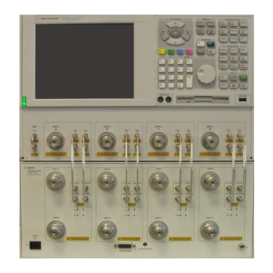
U3042AE08 Introduction Introd uction This document describes how to use the U3042AE08 Multiport Test Set with the Keysight N5230C 4-Port PNA-L Network Analyzer and the N5242A PNA-X for a 12-Port Network Analyzer solution. Figure 1 N5230C 4-Port PNA-L with U3042AE08... -
Page 9: Description
U3042AE08 Description Description The U3042AE08 is a Multiport Test Set that adds 8 ports to extend the 4-Port network analyzer to 12 full crossbar test ports with N-Port calibration capability. The U3042AE08 has the following key features: • 8 test ports (3.5 mm male connectors) •... -
Page 10: Network Analyzer Requirement
1. The image does not show the exact analyzer, but the port configuration is similar. Ensure that the network analyzer has the latest firmware version installed. The following web site links provide the necessary information needed: • Network Analyzer - http://www.keysight.com/find/pna • U3042AE08 Test Set Files - http://na.support.keysight.com/multiport (see test set files) -
Page 11: Available Options
U3042AE08-1CN Front Handle Kit (5063-9228) Network Analyzer Interface Kit Options The U3042AE08 requires one of the following kits to interface the test set with your network analyzer. The interface kit model option includes the hardware lock-link and cable kit listed in... -
Page 12: General Specifications
Actual performance of the system is based on the customers analyzer and options that are used with the test set. A functional certificate is only offered for the U3042AE08. When connected to a network analyzer, this test set will degrade the performance at the test ports. The internal switch paths reduce test port power and power to the receivers. -
Page 13: Environmental Requirements
U3042AE08 General Specifications Environmental Requirements Refer to your analyzer’s standard documentation for environmental requirements. The PNA-L provides front panel access to the source outputs, receiver inputs and couplers for use with multiport test sets. Environmental Tests The test set complies with all applicable safety and regulatory requirements for the intended location of use. -
Page 14: Frequency Range And Maximum Power Levels
It is recommend that you do not operate components near damage levels (+30 dBm). The power levels must be 3 dB below maximum level to ensure no damage. Table 5 Power Levels Maximum U3042AE08 Test Port RF Power Level: PORT 5-12 +27 dBm Maximum U3042AE08 Access Ports:... -
Page 15: Typical Reflection Tracking
U3042AE08 General Specifications Typical Reflection Tracking Specifications for the test set are typical. System performance for the analyzer and test set are only characteristic and intended as non warranted information. Typical specifications are based on 1 to 2 units performance. Refer to... -
Page 16: Front And Rear Panel Features
U3042AE08 Front and Rear Panel Features Front and Rear Panel Features Figure 3 Front Panel (Multiport Test Set) 5 of 12 Test Ports Access Port CPLR ARM SOURCE IN CPLR THRU RCVR OUT Active Standby Switch Control Voltage Test Port LEDs... -
Page 17: Standby Switch
U3042AE08 Front and Rear Panel Features Stand by Switch Note that this switch is Standby only, not a line switch. The main power cord can be used as the system disconnecting device. It disconnects the mains circuits from the mains supply. -
Page 18: Line Module
U3042AE08 Front and Rear Panel Features Line Module The line fuse, as well as a spare, reside within the line module. Figure 5 illustrates where the fuses are located and how to access them. Available Fuses • Fuse (F 5 A/250V, 2110-0709) UL listed and CSA certified For continued protection against a fire hazard, replace the line fuse only with the same type and rating. -
Page 19: Hardware Lock-Link Installation (U3021-60001)
U3042AE08 Hardware Lock-link Installation (U3021-60001) Hardware Lock-link Installation (U3021-60001) The opening of covers or removal of parts is likely to expose dangerous voltages. Disconnect the instrument from all voltage sources while it is being opened. Locking the Test Set to the PNA-L 1. - Page 20 U3042AE08 Hard ware Lock-link Installation (U3021-60001) 4. Install the lower lock-links (left not shown) onto the analyzer. Figure 7 Install Lock-links to the Analyzer Screws (0515-1619) T20 M4X0.7 25 mm Right lock-link 5023-0132 (pair 5. Remove the two upper standoffs from the rear panel on the test set using a T20 Torx driver.
- Page 21 U3042AE08 Hardware Lock-link Installation (U3021-60001) 7. Place the network analyzer on top of the test set and ensure that the front frame of the network analyzer is positioned slightly forward of the locks that are attached to the test set. Slide the network analyzer back so the locks engage the front frame of the analyzer.
-
Page 22: Hardware Lock-Link Installation (U3021-60002)
U3042AE08 Hard ware Lock-link Installation (U3021-60002) Hardware Lock-link Installation (U3021-60002) The opening of covers or removal of parts is likely to expose dangerous voltages. Disconnect the instrument from all voltage sources while it is being opened. Locking the Test Set to the PNA-X The lock-link kit (U3021-60002) includes: •... - Page 23 U3042AE08 Hardware Lock-link Installation (U3021-60002) 4. Install the lower lock-links (left not shown) onto the analyzer. Figure 12 Install Lock-links on the Analyzer Screws (0515-1619) T20 M4X0.7 25 mm Right lock-link 5023-0132 (pair) 5. Remove the two upper standoffs from the rear panel of the test set using a T20 torx driver.
- Page 24 U3042AE08 Hard ware Lock-link Installation (U3021-60002) 7. Place the analyzer on top of the test set and ensure that the front frame of the analyzer is positioned slightly forward of the locks that are attached to the test set. Slide the analyzer back so the locks engage the front frame of the analyzer.
-
Page 25: Pna-L Rf Interface Cable Connections (U3021-60045)
U3042AE08 PNA-L RF Interface Cable Connections (U3021-60045) PNA-L RF Interface Cable Connections (U3021-60045) Figure 16 on page 20 illustrates the cable configuration of the test set to the analyzer. The cables have been supplied with Cable Kit (U3021-60045). 1. Remove the SOURCE OUT to CPLR THRU and RCVR IN to CPLR ARM jumpers (x16) on the analyzer. The RCVR R1-R4 to SOURCE OUT reference loop jumpers (x1) remain on the front panel. - Page 26 SOURCE CPLR CPLR SOURCE CPLR SOURCE CPLR SOURCE SOURCE Test Set I/O Cable Z5623-20418 (short) U3042AE08 10 MHz to 20 GHz MULTIPORT TEST SET PORT 5 PORT 6 PORT 7 PORT 8 CPLR CPLR CPLR CPLR SOURCE SOURCE...
-
Page 27: Pna Or Pna-X Rf Interface Cable Connections (U3021-60047)
U3042AE08 PNA or PNA-X RF Interface Cable Connections (U3021-60047) PNA or PNA-X RF Interface Cable Connections (U3021-60047) Figure 17 on page 22 illustrates the setup configuration of the test set to the analyzer. The cables have been supplied with Cable Kit (U3021-60047). - Page 28 U3042AE08 PNA or PNA-X RF Interface Cable Connections (U3021-60047) Figure 17 llustrates the final two digits of the part number for each cable. The cables must be connected . in the numeric order listed in Table 9 on page 21...
-
Page 29: Test Set I/O Cable Installation
U3042AE08 Test Set I/O Cable Installation Test Set I/O Cable Installation Connect the Test Set I/O cable (N4011-21002) to the test set Interface connector on the rear panel, similar to Figure Figure 18 Test Set I/O Cable Connection Interconnect Cable Verification 1. -
Page 30: System Operational Checks
U3042AE08 System Operational Checks System Operational Checks The following procedure will confirm that the RF interface cables between the test set and analyzer are installed and the system is working correctly. Ensure that your analyzer is calibrated by measuring the short on each port before connecting the test set. - Page 31 U3042AE08 System Operational Checks The trace ripple (peak-peak variation) will be higher than when using an ECal Module due to variation in your Short’s performance. If response is in question perform “Cal Kit Operational Check” on page Figure 19 Typical Reflection Response Ports 1 to 4 (Std)
- Page 32 PNA & PNA-X Port orientation is shown. PNA-L RF interconnections are the same. ( PNA-L ) Port 1 Port 3 (2) Port 4 (3) Port 2 (4) S33 (S22) S44 (S33) S22 (S44) U3042AE08 Opt 001 RCVR SIGNAL RF Diagram SOURCE SIGNAL Solid State Switches S101 S201 S301 S401...
- Page 33 U3042AE08 System Operational Checks Figure 23 Typical Reflection Response Ports 5 to 12 (Std) Figure 24 Reflection Response Signal Path Diagram Ports 5 to 8 (Std) NOTE: 4-Port PNA PNA & PNA-X Port orientation is shown. PNA-L RF interconnections are the same.
- Page 34 U3042AE08 System Operational Checks Figure 25 Reflection Response Signal Path Diagram Ports 9 to 12 (Std) NOTE: 4-Port PNA PNA & PNA-X Port orientation is shown. PNA-L RF interconnections are the same. ( PNA-L ) Port 1 Port 3 (2)
- Page 35 PNA & PNA-X Port orientation is shown. PNA-L RF interconnections are the same. ( PNA-L ) Port 1 Port 3 (2) Port 4 (3) Port 2 (4) U3042AE08 Opt 001 RCVR SIGNAL RF Diagram SOURCE SIGNAL Solid State Switches S101...
- Page 36 PNA & PNA-X Port orientation is shown. PNA-L RF interconnections are the same. ( PNA-L ) Port 1 Port 3 (2) Port 4 (3) Port 2 (4) U3042AE08 Opt 001 RCVR SIGNAL RF Diagram SOURCE SIGNAL Solid State Switches S101...
-
Page 37: Controlling The Test Set
U3042AE08 Controlling the Test Set Controlling the Test Set This section will describe how to setup and operate the test set with the N5242A or N5230C. The test set is considered a “slave” instrument. A N5230C or N5242A must be used to control the test set. -
Page 38: Analyzer Multiport Mode For Option 551
[Utility] > System > Configure > Multiport Capability. Select U3042AE08 (12-Port System) from the drop-down menu and select Restart as a multiport PNA with this testset > OK. The analyzer will restart the network application with the test set interface features. -
Page 39: External Test Set Control Feature
This menu will allow the physical Ports 1 thru 12 to be identified as any port for your convenience. For example; Port 5 can be named Port 2. The External Test Set Control-U3042AE08 also allows control of the DUT control lines, refer to “Control Lines”... -
Page 40: Trace Measure S-Parameter
U3042AE08 Controlling the Test Set Trace Measure S-Parameter S-Parameter selection can be accomplished using Response > Measure. Use the drop-down menus to select 1 of 144 S-Parameters for the 12-Port system. The first number in the Sxx selection is the Receiver Port and the second number will be the Source Port. - Page 41 U3042AE08 Controlling the Test Set Figure 33 12-Port New Trace Measure (S11 - S55) Use the scroll bar to select other s-parameter measurements Figure 34 12-Port New Trace Measure (S88 - S1212)
- Page 42 U3042AE08 Controlling the Test Set Balanced Tab: Balanced Measurements can be configured by selecting the Balance tab in the New Measurement menu. For more information on balanced (differential) component measurement, refer to the Application Note 1373-1 and 1373-2 (5988-5634EN and 5988-5635EN) at http://www.home.keysight.com. In the search menu type in “Multiport and Balanced.”...
-
Page 43: Sweep Setup For Multiport And Standalone Modes
U3042AE08 Controlling the Test Set Sweep Setup for Multiport and Standalone Modes When the test set is connected to the analyzer, it is recommended that the analyzer’s Sweep Setup be configured to Stepped Sweep before calibrating. This is slower than the Analog Sweep, but is more accurate due to the extra electrical length of the test set and test port cables. -
Page 44: N-Port Calibration With Analyzer
U3042AE08 Controlling the Test Set N-Port Calibration with Analyzer It is recommended that you perform an ECal characterization to minimize the connections required for multiple port calibration. The N4691B Option M0F is recommended with cable (85131F) if you are calibrating at the analyzer and test set ports. - Page 45 U3042AE08 Controlling the Test Set Continue following the Cal Wizard prompts. On the “Select Calibration Ports and ECal Module” window, press Select All or select the ports you are calibrating and press Next. If using a mechanical cal kit, select SmartCal (Guided Calibration) > Next.
-
Page 46: Interface Control Mode
U3042AE08 Controlling the Test Set Interface Control Mode Interface Control mode will not function properly when using multiport mode. Multiport mode will reset the switch path commands of the interface control. It is recommended that the network analyzer be restarted in stand-alone mode if the interface control is being used. -
Page 47: Using Interface Control Mode
U3042AE08 Controlling the Test Set Using Interface Control Mode An Instrument Preset will reset all of the fields to their default settings. If an error is encountered when sending Interface Control data, an error message is displayed on the screen and the Channel Trigger State is set to Hold. You must fix the condition that caused the error, then change the Channel Trigger State to its original setting. - Page 48 U3042AE08 Controlling the Test Set Channel 1: (4) Specifies the channel number for dialog settings. Each channel is configured individually. The drop down menu illustrates the channels that currently have measurements. There must be at least one displayed trace for the Test Set I/O interface to function.
-
Page 49: Gpib Control Mode
U3042AE08 Controlling the Test Set GPIB Control Mode The GPIB Command Processor feature allows you to send remote commands and data to the analyzer’s rear-panel GPIB connector and Test Set I/O connector. More information regarding the GPIB Command Processor can be found in the Help menu. -
Page 50: Gpib Command Processor Console
U3042AE08 Controlling the Test Set GPIB Command Processor Console Write Commands Once the GPIB Command Processor Console is open, commands can remotely control the external test set I/O connector by sending the following: address: a integer number data: a integer number Address and data are separated by a comma. -
Page 51: Address And Data Values
U3042AE08 Address and Data Values Address and Data Values Setting the Test Port Paths with Address and Data Refer to Table 11 Figure 44 on page 46 for information to set the internal switch paths of the test set. The address is the first value in the Test Set I/O control or GPIB data command. The second value controls the source and receiver paths of the ports. - Page 52 U3042AE08 Address and Data Values Figure 44 Example 1; Address and Data (Ports 9 & 10) NOTE: 4-Port PNA PNA & PNA-X Port orientation is shown. PNA-L RF interconnections are the same. ( PNA-L ) Port 1 Port 3 (2)
-
Page 53: Control Lines
U3042AE08 Control Lines Control Lines The 15 pin female D-Sub connector on the front panel provides 8 latched data lines that can be used to control your device under test (DUT). The lines can be controlled with the Multiport External Test Set control, or Test Set I/O commands. - Page 54 U3042AE08 Control Lines Figure 45 DUT control Line Pin Assignment (rear panel view) Table 13 DUT Control Line Pin Assignment Signal Name Description Line 1 Control Line Output of the voltage from pin 13 or pin 14. Line 2 Control Line Output of the voltage from pin 13 or pin 14.
-
Page 55: Internal Voltage Supply Configuration
U3042AE08 Control Lines Internal Voltage Supply Configuration The output voltage of pin 12 can be varied from +2 to +5 V. Perform the following procedure to set the voltage: 1. Turn On the test set. 2. Measure the voltage between pin 12 and 15 using a multimeter. -
Page 56: External Voltage Supply Configuration
U3042AE08 Control Lines External Voltage Supply Configuration Figure 46 illustrates an example of the connection with an external DC power supply. Connect the positive and negative voltage supply from the external power supply to the positive input (pin 13) and the negative .... -
Page 57: Setting The Control Lines With Address And Data Values
U3042AE08 Control Lines Setting the Control Lines with Address and Data Values This section describes how to control the rear panel DUT control lines. The following control feature will function only while the analyzer is in Standalone Mode. Setting the Network Analyzer to Standalone Mode. - Page 58 U3042AE08 Control Lines After a power reset all DUT control lines are initially configured to a logic high state or connected to Pin 13, refer to Figure 46 on page 49. To reset all control lines to logic high, without having to reset the power switch on the test set, make the following analyzer entry: Front panel analyzer Interface Control Mode line entry = 112.0 >...
-
Page 59: Cal Kit Operational Check
Refer to “General Specifications” on page Equipment Required The Keysight U3042AE08 requires that the user be familiar with the equipment and components listed in Table This section provides an equipment list and setup of the analyzer and test set. -
Page 60: Verification Limits
Only a functional certificate is provided for the U3042AE08. It is recommended that you return your instrument to Keysight Technologies for servicing or repair if the test set and analyzer performance exceed the operational verification limits. -
Page 61: Operational Check Procedure
4. Verify that the analyzer is in 12-Port. See the bottom of the measurement window. a. If only four S-Parameters are listed, press Utility > System > Configure > Multiport Capability. On the Multiport Restart dialog, select Restart as multiport PNA with this test set. Select U3042AE08 (12-Port). -
Page 62: 1-Port Calibration And Verification Procedure
U3042AE08 Cal Kit Operational Check 1-Port Calibration and Verification Proced ure 1. Connect the ECal or the mechanical cal kit to Port 1 or the port you are testing. Torque to 8 in-lb. For more information press the Help button, see Figure 2. -
Page 63: Cal Set Verification
U3042AE08 Cal Kit Operational Check Cal Set Verification Select Trace/Chan > Trace > Delete Trace. There should be no traces on the display. 2. To launch the Cal Set Viewer toolbar. Select Response > CAL > Manage CALS > ... - Page 64 U3042AE08 Cal Kit Operational Check Figure 52 Option 001 or 002 Reflection Tracking Trace (Port 1-12) with N5230C Figure 53 Standard Reflection Tracking Trace (Port 1-12) with N5230C...
-
Page 65: Reflection Tracking Plot Examples
U3042AE08 Cal Kit Operational Check Reflection Tracking Plot Examples Figure 54 Option 001 or 002 Reflection Tracking Trace (Port 1-4) with N5242A Figure 55 Option 001 or 002 Reflection Tracking Trace (Port 5-12) with N5242A Response from 10 MHz to 500 MHz is normal due to the PNA-X Couplers in comparison to... - Page 66 U3042AE08 Cal Kit Operational Check Figure 56 Standard Reflection Tracking Trace (Port 1-4) with N5242A Figure 57 Standard Reflection Tracking Trace (Port 5-12) with N5242A Response from 10 MHz to 500 MHz is normal due to the PNA-X couplers in comparison to...
-
Page 67: Verifying Cal Kit Operational Check Failures
U3042AE08 Verifying Cal Kit Operational Check Failures Verifying Cal Kit Operational Check Failures If your test results fail the Operational Check limits, see Table 6 Table 7 on page 9 and verify the following: 1. Ensure that the test set is turned on and connected properly to the analyzer. -
Page 68: Service Information
Service Information Service Information There are many other repair and calibration options available from the Keysight Technologies support organization. These options cover a range of service agreements with varying response times. Contact Keysight for additional information on available service agreements for this product. -
Page 69: Electrostatic Discharge Protection
U3042AE08 Service Information Keysight Description Part Number PNA-X Test Set Rear Lock Feet (left) N5242-20139 PNA-L or PNA-X Locking Feet 5023-0132 PNA-L Test Set Locking Feet 5063-9253 U3042A Option E08 U3042-90002 User’s and Service Guide Electrostatic Discharge Protection Electrostatic discharge (ESD) can damage or destroy electronic components. The product is shipped in materials that prevent damage from static, and should only be removed from the packaging in an anti-static area ensuring that the correct anti-static precautions are taken. -
Page 70: System Block Diagram
U3042AE08 System Block Diagram System Block Diagram Figure 59 U3042AE08 Standard Configuration CPLR THRU SOURCE OUT CPLR ARM RCVR A IN CPLR THRU SOURCE OUT CPLR ARM RCVR C IN CPLR THRU SOURCE OUT CPLR ARM RCVR D IN CPLR THRU... - Page 71 U3042AE08 System Block Diagram Figure 60 U3042AE08 Option 001 Configuration CPLR THRU SOURCE OUT CPLR ARM RCVR A IN CPLR THRU SOURCE OUT CPLR ARM RCVR C IN CPLR THRU SOURCE OUT CPLR ARM RCVR D IN CPLR THRU SOURCE OUT...
- Page 72 U3042AE08 System Block Diagram Figure 61 U3042AE08 Option 002 Configuration CPLR THRU SOURCE OUT CPLR ARM RCVR A IN CPLR THRU SOURCE OUT CPLR ARM RCVR C IN CPLR THRU SOURCE OUT CPLR ARM RCVR D IN CPLR THRU SOURCE OUT...
-
Page 73: Theory Of Operation
U3042AE08 Theory of Operation Theory of Operation The following is a description of the operation of the test set. Reference the test set block diagrams shown “System Block Diagram” beginning on page 64. This section assumes the user has a general... -
Page 74: Test Set Switch Paths
U3042AE08 Theory of Operation Test Set Switch Paths S100 - Source Switch 100 provides control of the Source Output path to PNA Port 1 and test set Port Output to Ports 5 and 9. In the state shown in the block diagram, switch 100 routes the RF Source (1, 5 and 9) back to the PNA Port 1, and the test set Source path to Port 5 and 9 is terminated. -
Page 75: Pna-X Switch Paths
U3042AE08 Theory of Operation PNA-X Switch Paths S100 - Source Switch 100 provides control of the Source Output path to PNA Port 1 and test set Port Output to Ports 5 and 9. In the state shown in the block diagram, switch 100 routes the RF Source (1, 5 and 9) back to the PNA Port 1, and the test set Source path to Port 5 and 9is terminated. -
Page 76: Troubleshooting The Test Set
U3042AE08 Troubleshooting the Test Set Troubleshooting the Test Set If the test set is not operating properly, use the following procedures to isolate the problem. It is recommended that a qualified service technician perform the following procedures. Refer to the Keysight PNA Series: Service & Support Home Page at: ... - Page 77 If the rear panel or deck fans is not operating and the DC Indicator LEDs are on; replace fan. Figure 64 Test Set Diagram Keysight U3042AE08 8-Port Test Set 10 MHz 26.5 GHz Ext. DUT...
- Page 78 U3042AE08 Troubleshooting the Test Set 6. Front Panel R and S indicator LED Check. Verify the test set’s Controller board Controller Status LEDs, shown in Figure 63 on page a. If none are on remove the Switch Driver board and recheck, if still no indication, replace the Controller board.
-
Page 79: Rf Switching Path Test
U3042AE08 Troubleshooting the Test Set RF Switching Path Test If you suspect an RF signal path problem with the test set and have verified that the problem in not the front panel RF interface cables, the following procedure will check all of the RF signal paths through the test set. - Page 80 U3042AE08 Troubleshooting the Test Set Table 18 Signal Path Connections and Commands PNA Port-2 to PNA Port-1 to <Addr>.<Data> Path Components Response (typical) Test Set Test Set PNA-L Ports 1 & 5 or PNA/PNA-X Ports 1 & 5...
- Page 81 U3042AE08 Troubleshooting the Test Set Table 18 Signal Path Connections and Commands PNA Port-2 to PNA Port-1 to <Addr>.<Data> Path Components Response (typical) Test Set Test Set PNA-L Ports 1 & 9 or PNA/PNA-X Ports 1 & 9...
- Page 82 U3042AE08 Troubleshooting the Test Set Figure 65 Source IN to Ports 5-8 Path Response (Std/001) Figure 66 Source IN to CPLR THRU Path Response (Std/001)
- Page 83 U3042AE08 Troubleshooting the Test Set Figure 67 RCVR OUT to Ports 5-8 Path Response (Std) Figure 68 RCVR OUT to Ports 5-8 Path Response (Option 001)
- Page 84 U3042AE08 Troubleshooting the Test Set Figure 69 RCVR OUT to CPLR ARM Path Response (Std) Figure 70 RCVR OUT to CPLR ARM Path Response (Option 001)
-
Page 85: Connection Tables And Diagrams
U3042AE08 Connection Tables and Diagrams Connection Tables and Diagrams Table 19 Controller Board Connection Controller Board Connections LED Ribbon Cables from the LED Board: Port 5 & 9 Port 6 & 10 Port 7 & 11 Port 8 & 12... - Page 86 U3042AE08 Connection Tables and Diagrams Figure 71 Top View (Std) DUT Control Bd Coupler/ Bridge (x4) Quad Switch (x4) Switch Interface Bd. (top Bd) Control Bd (bottom Bd)
- Page 87 U3042AE08 Connection Tables and Diagrams Figure 72 Bottom View (Std/001) Quad Switch (x4) Fuse (x2) Power Supply Line Module...
-
Page 88: Safety And Information
U3042AE08 Safety and Information Safety and Information Introduction Review this product and related documentation to familiarize yourself with safety markings and instructions before you operate the instrument. This product has been designed and tested in accordance with accepted industry standards, and has been supplied in a safe condition. -
Page 89: Before Applying Power
U3042AE08 Safety and Information Before Applying Power Verify that the premises electrical supply is within the range of the instrument. The instrument has an autoranging power supply. If this prod uct is not used as specified, the protection provided by the equipment could be impaired. - Page 90 U3042AE08 Safety and Information Danger of explosion if battery is incorrectly replaced. Replace only with the same or equivalent type recommended. Discard used batteries accord ing to manufacturer’s instructions. For continued protection against fire hazard replace line fuse only with same type and rating.
-
Page 91: Regulatory Information
U3042AE08 Regulatory Information Regulatory Information Instrument Markings Listed below are definitions for the markings that may be found on the product. The instruction documentation symbol. The product is marked with this symbol when it is necessary for the user to refer to the instructions in the documentation. - Page 92 Regulatory Information Battery: Do not throw batteries away but collect as small chemical waste, or in accordance with your country’s requirements. You may return the battery to Keysight Technologies for disposal. Refer to “Contacting Keysight” on page 84 for assistance.
-
Page 93: Keysight Technical Support And Services
Keysight Technical Support and Services Keysight Technical Support and Services There are many other repair and calibration options available from the Keysight Technologies support organization. These options cover a range of service agreements with varying response times. Contact Keysight for additional information on available service agreements for this product. - Page 94 This information is subject to change without notice. © Keysight Technologies 2011-2018 Edition 4, July 2018 Supersedes: July 2017 U3042-90002 www.keysight.com...
Need help?
Do you have a question about the U3042AE08 and is the answer not in the manual?
Questions and answers