Table of Contents
Advertisement
Quick Links
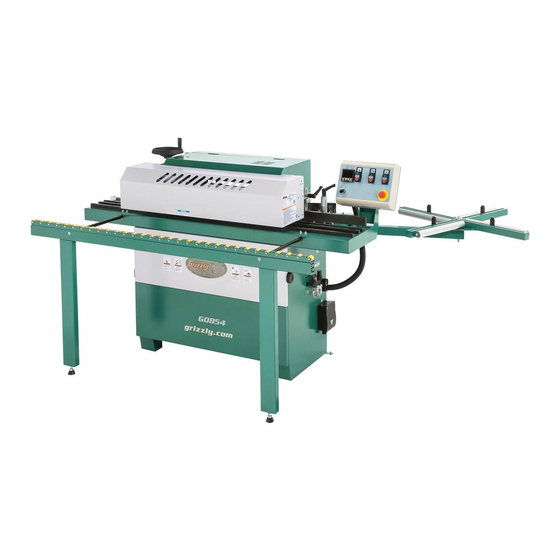
MODEL G0854
AUTOMATIC EDGEBANDER
OWNER'S MANUAL
(For models manufactured since 08/18)
COPYRIGHT © JANUARY, 2019 BY GRIZZLY INDUSTRIAL, INC.
WARNING: NO PORTION OF THIS MANUAL MAY BE REPRODUCED IN ANY SHAPE
OR FORM WITHOUT THE WRITTEN APPROVAL OF GRIZZLY INDUSTRIAL, INC.
V1.01.19
#ES19664 PRINTED IN TAIWAN
Advertisement
Table of Contents

Subscribe to Our Youtube Channel
Related Manuals for Grizzly G0854


Summary of Contents for Grizzly G0854
- Page 1 (For models manufactured since 08/18) COPYRIGHT © JANUARY, 2019 BY GRIZZLY INDUSTRIAL, INC. WARNING: NO PORTION OF THIS MANUAL MAY BE REPRODUCED IN ANY SHAPE OR FORM WITHOUT THE WRITTEN APPROVAL OF GRIZZLY INDUSTRIAL, INC. V1.01.19 #ES19664 PRINTED IN TAIWAN...
- Page 2 This manual provides critical safety instructions on the proper setup, operation, maintenance, and service of this machine/tool. Save this document, refer to it often, and use it to instruct other operators. Failure to read, understand and follow the instructions in this manual may result in fire or serious personal injury—including amputation, electrocution, or death.
-
Page 3: Table Of Contents
Table of Contents INTRODUCTION ..........2 SECTION 8: WIRING ........58 Contact Info............ 2 Wiring Safety Instructions ......58 Manual Accuracy ........... 2 Electrical Panel Wiring Diagram ....59 Identification (Front) ........3 Terminal Block Wiring Diagram ....60 Identification (Rear)........4 Motor Wiring Diagrams ........ -
Page 4: Introduction
To reduce your risk of serious injury, read this entire manual BEFORE using machine. Manufacture Date Serial Number Model G0854 (Mfd. Since 08/18) -
Page 5: Identification (Front)
Use this machine with respect and caution to decrease the risk of operator injury. If normal safety precautions are overlooked or ignored, serious personal injury may occur. Model G0854 (Mfd. Since 08/18) -
Page 6: Identification (Rear)
Edge Seat Height Glue Flow Flush Trimmer Adjustment Knob Adjustment Knob Adjustment Knobs 4" Dust Ports Rear Access Cover Nylon Roller Release Knob Glue Spindle Adjustment Knob Flush Rear Access Electrical Panel Trimmer Panel Doors Motor Model G0854 (Mfd. Since 08/18) -
Page 7: Controls & Components
Not intended for end-user adjustment. Qualified service personnel only! D. Temperature DOWN Key: Incrementally lowers temperature of glue pot when pressed. E. Temperature UP Key: Incrementally raises temperature of glue pot when pressed. Model G0854 (Mfd. Since 08/18) - Page 8 U. Glue Pot w/Lid: Stores and heats glue for coil guillotine activates and blade severs bonding edgebanding to workpiece. Remove edgebanding from roll. lid to inspect glue pot or to add glue. Leave closed during operations. Model G0854 (Mfd. Since 08/18)
- Page 9 — When trailing edge of workpiece passes roller against edgebanding and workpiece. over and releases first switch, end trimmer Tighten to decrease pressure. guillotine activates, moves into cut posi- tion, and left blade severs trailing end of glued edgebanding. Model G0854 (Mfd. Since 08/18)
- Page 10 AD. Flush Trimmer Cutters (Upper and Lower): Note: For best results, always adjust upper Rotates at approximately 10,000 RPM and and lower flush trimmer cutters equally. trims height of glued edgebanding, making it flush with top and bottom of workpiece. Model G0854 (Mfd. Since 08/18)
- Page 11 Handwheel base features a readout that displays height in millimeters. Note: Panel feeder elevation handwheel also raises and lowers upper portions of flush trim- ming unit (see Page 8 for more information). Model G0854 (Mfd. Since 08/18)
- Page 12 Use Edgebanding tion to advance edgebanding. Seat Adjustment Knob (AM) to adjust seat according to edgebanding width. -10- Model G0854 (Mfd. Since 08/18)
- Page 13 AT. Fence Stop: Allows you to quickly and easily set the infeed fence position without having to use the scale (refer to Page 35 for details). AU. Fence Adjustment Scale: Indicates position of fence relative to edgebanding thickness in millimeter increments. -11- Model G0854 (Mfd. Since 08/18)
-
Page 14: Machine Data Sheet
Type ..........................TEFC Capacitor-Start Induction Horsepower ................................1/3 HP Voltage ..................................220V Phase ................................Single-Phase Amps ..................................1.7A Speed ................................1700 RPM Power Transfer ..............................Gear Drive Bearings ........................Sealed & Permanently Lubricated -12- Model G0854 (Mfd. Since 08/18) Model G0854 Page 1 of 3... - Page 15 Approximate Assembly & Setup Time ..........................1 Hour Serial Number Location ..........................Machine ID Label Sound Rating ..................................79 dB ISO 9001 Factory ..................................Yes Certified by a Nationally Recognized Testing Laboratory (NRTL) ..................No -13- Model G0854 (Mfd. Since 08/18) Page 2 of 3 Model G0854...
- Page 16 Digital Control Panel Teflon-Coated Glue Pot With 5 Heating Elements and Motorized Glue Spreader 31-1/2" Tape Coil Support Two 4" Dust Ports Built-In Air Regulator and Filter for Pneumatic System -14- Model G0854 (Mfd. Since 08/18) Model G0854 Page 3 of 3...
-
Page 17: Section 1: Safety
Never operate under the influence of drugs or injury or blindness from flying particles. Everyday alcohol, when tired, or when distracted. eyeglasses are NOT approved safety glasses. -15- Model G0854 (Mfd. Since 08/18) - Page 18 Make sure they are properly installed, you experience difficulties performing the intend- undamaged, and working correctly BEFORE ed operation, stop using the machine! Contact our operating machine. Technical Support at (570) 546-9663. -16- Model G0854 (Mfd. Since 08/18)
-
Page 19: Additional Safety For Automatic Edgebanders
Use this and other machinery with caution and respect. Failure to do so could result in serious personal injury, damage to equipment, or poor work results. -17- Model G0854 (Mfd. Since 08/18) -
Page 20: Section 2: Power Supply
To reduce the risk of these hazards, avoid over- loading the machine during operation and make sure it is connected to a power supply circuit that meets the specified circuit requirements. -18- Model G0854 (Mfd. Since 08/18) - Page 21 Minimum Gauge Size ......12 AWG all local codes and ordinances. Maximum Length (Shorter is Better)..50 ft. -19- Model G0854 (Mfd. Since 08/18)
-
Page 22: Section 3: Setup
IMPORTANT: Save all packaging materials until you are completely satisfied with the machine and have resolved any issues between Grizzly or the shipping agent. You MUST have the original pack- aging to file a freight claim. It is also extremely helpful if you need to return your machine later. -
Page 23: Inventory
—Roller Slide Nuts M8-1.25 ....... 4 H. Coil Support Stud Assembly ...... 1 —Stud-FT M10-1.5 x 150 ......1 —Lock Nut M10-1.5 ........1 —Hex Nuts M10-1.5 ........2 —Fender Washers 10mm ......3 Figure 13. Hardware bag contents. -21- Model G0854 (Mfd. Since 08/18) -
Page 24: Hardware Recognition Chart
Hardware Recognition Chart USE THIS CHART TO MATCH UP HARDWARE DURING THE INVENTORY AND ASSEMBLY PROCESS. Flat Head Screw -22- Model G0854 (Mfd. Since 08/18) -
Page 25: Site Considerations
Wall = Electrical Connection Min. 30" for Maintenance " " Feed Direction Keep Keep " Workpiece Workpiece Unloading Loading Area Area Unobstructed Unobstructed Figure 14. Minimum working clearances. -23- Model G0854 (Mfd. Since 08/18) -
Page 26: Lifting & Placing
The leveling bolts are located at rear left and right corners of machine. Leveling Bolt Jam Nut Figure 16. Location of (1 of 2) leveling bolts with jam nuts. -24- Model G0854 (Mfd. Since 08/18) -
Page 27: Assembly
(if applicable). Assembling the Model G0854 requires reposition- ing the control panel, installing the coil support assembly, installing the panel feeder elevation handwheel, and aligning the table extension with the table. - Page 28 Thread stud up through bottom of coil support port arm (see Figure 21). arm (see Figure 23). Stud Coil Support Coil Support Hex Nut Fender Washer Figure 21. Coil support arm installed. Figure 23. Stud threaded into coil support arm. -26- Model G0854 (Mfd. Since 08/18)
- Page 29 10mm fender washer removed in Step 6 (see Guide Roller Figure 25). Slot Coil Support Lock Nut Assembly Washer Fender Washer Slide Nut Figure 27. Guide roller installed in coil support slot. Figure 25. Coil support assembly installed. -27- Model G0854 (Mfd. Since 08/18)
- Page 30 Figure 31. Location of end-trimming guillotine shipping tag to be removed. 15. Pull out extension table (see Figure 32) as far as it goes. Figure 29. Location of wood shipping blocks to be removed. Figure 32. Extension table extended. -28- Model G0854 (Mfd. Since 08/18)
-
Page 31: Cleanup
Extension pletely removed. Table Leg Jam Nut Adjustable Adjustable Foot Nut Foot Figure 34. Location of extension table alignment components. 18. Repeat Steps 16–17 for outfeed (left) end of table. -29- Model G0854 (Mfd. Since 08/18) -
Page 32: Dust Collection
Tug hoses to make sure they do not come off. A tight fit is necessary for proper performance. Figure 35. T23692 Orange Power Degreaser. Figure 36. Dust hoses attached to dust ports. -30- Model G0854 (Mfd. Since 08/18) -
Page 33: Test Run
Figure 38. Thermoregulator display illuminated after master power switch turned ON. Turn glue pot ON (see Figure 38). Note: Glue pot filled with glue at factory. -31- Model G0854 (Mfd. Since 08/18) - Page 34 OFF and disconnect machine ment and thermoregulator display. from power. The feeder panel safety limit switch is not working correctly. This safety feature must work correctly before proceeding with regular operations. Call Tech Support for help. -32- Model G0854 (Mfd. Since 08/18)
-
Page 35: Section 4: Operations
Regardless of the content in this sec- 15. When finished, stops machine, turns it OFF, tion, Grizzly Industrial will not be held liable and disconnects it from power and air supply. for accidents caused by lack of training. -
Page 36: Checking/Adding Glue
Tip: Add small amounts of glue pellets fre- quently for better melting consistency. Figure 42. Panel feeder elevation handwheel with numerical display. Retighten panel feeder lock lever (see Figure 41) to secure panel feeder. -34- Model G0854 (Mfd. Since 08/18) -
Page 37: Setting Infeed Fence Position
(see Figure 43), then retighten lock fence position. lever. Rotate knurled cylinder until stop plate press- es firmly against scrap piece, then tighten infeed fence lock lever to secure setting. -35- Model G0854 (Mfd. Since 08/18) -
Page 38: Checking/Adjusting Glue Spindle Position
Proceed to Step 4. Workpiece Contacting Glue Spindle Workpiece Contacting Infeed Fence Figure 45. Example of checking glue spindle position. -36- Model G0854 (Mfd. Since 08/18) -
Page 39: Adjusting Flush Trimmer
The Model G0854 Automatic Edgebander The flush trimmer consists of two cutterheads uses edgebanding tape from ⁄... - Page 40 Loosen edgebanding height knobs from Step 2 on Page 37, adjust knobs until edge- banding tape has just enough room to move freely back and forth, then tighten to secure. Leave approximately ⁄ " vertical play. -38- Model G0854 (Mfd. Since 08/18)
-
Page 41: Performing Edgebanding Operation
Any workpiece you intend to edgeband with the G0854 must have at least one straight and square edge that is at least 11" long. It is always best to start with a test piece of the... - Page 42 12. Receive edgebanded workpiece at outfeed end of table (see Figure 54). Allow panel feeder to completely finish feeding workpiece, then remove workpiece from table. -40- Model G0854 (Mfd. Since 08/18)
-
Page 43: Section 5: Accessories
Features thumb roll and stainless steel construc- To reduce this risk, only install accessories tion. Range: 0-6", 0-150mm. Resolution: 0.0005", recommended for this machine by Grizzly. 0.01mm, ⁄ ." NOTICE Refer to our website or latest catalog for additional recommended accessories. - Page 44 T20456—DAKURA Safety Glasses, Black/Clear T20502 G7914 G7916 G7915 T20503 T20452 G7911 T20456 T20451 Figure 60. Grizzly edgebanding hand tools. Figure 62. Assortment of basic eye protection. www.grizzly.com 1-800-523-4777 order online at or call -42- Model G0854 (Mfd. Since 08/18)
-
Page 45: Section 6: Maintenance
Lubricate flush-trimmer adjustment shafts. ing unpainted cast iron and steel. • Motor belt tension, damage, or wear. • Conveyor belt tension, damage, or wear. • Inspect entire machine for loose parts or signs of abnormal wear. -43- Model G0854 (Mfd. Since 08/18) -
Page 46: Lubrication
T26685—ISO 32 Moly-D Machine Oil, 1 gal. Figure 65. Location of glue spindle grease T26419—Syn-o-Gen® High-Speed Bearing fitting. Grease T26685 T26419 Figure 64. ISO 32 machine oil and high-speed bearing grease. -44- Model G0854 (Mfd. Since 08/18) - Page 47 To lubricate the gear, clean it with a stiff brush and mineral spirits and allow it to dry, then lightly grease the gear. Edgebanding Feed Gear Figure 66. Lubrication points on flush trimmer adjustment shafts. Figure 67. Location of edgebanding feed gear. -45- Model G0854 (Mfd. Since 08/18)
-
Page 48: Section 7: Service
7. Pulley/sprocket slipping on shaft. 7. Replace loose pulley/shaft. 8. Centrifugal switch at fault. 8. Adjust/replace centrifugal switch if available. 9. Motor bearings at fault. 9. Test by rotating shaft; rotational grinding/loose shaft requires bearing replacement. -46- Model G0854 (Mfd. Since 08/18) - Page 49 3. Heater rods at fault. 3. Inspect heater rod connections; tighten if necessary. Test heater rod amperage (top: 315W, 1.0A; lower large: 250W, 0.9A; lower small: 160W, 0.6A); replace if necessary. -47- Model G0854 (Mfd. Since 08/18)
- Page 50 1. Conveyor belt not properly tensioned. 1. Properly tension conveyor belt (Page 54). Workpiece feeds erratically or stops 2. Properly adjust panel feeder height (Page 34). 2. Panel feeder height not properly adjusted. feeding during operation. -48- Model G0854 (Mfd. Since 08/18)
- Page 51 1. Guillotine limit switch set too low. 1. Raise position of guillotine limit switch. edgebanding on 2. Panel feeder not exerting enough 2. Lower panel feeder to 0.5mm below actual finished workpiece. downward force on workpiece. workpiece thickness (34). -49- Model G0854 (Mfd. Since 08/18)
-
Page 52: Checking/Calibrating Infeed Fence Stop
If necessary, repeat Steps 5–6 until you can adjust fence to "0." Retighten lock lever. Tighten stop bolt until it contacts stop plate, then tighten jam nut to secure stop bolt. Infeed fence stop is now calibrated (see Figure 69). -50- Model G0854 (Mfd. Since 08/18) -
Page 53: Removing/Changing Glue
(refer to Page 34 for more information). Figure 70. Using wood stick to peel glue away from glue pot for glue removal. -51- Model G0854 (Mfd. Since 08/18) -
Page 54: Replacing Flush Trimmer Knives
Repeat Steps 3–4 with remaining knives on cutterhead. Block If necessary, repeat Steps 3–5 with knives of other cutterhead. Knife Close and lock panel feeder. (1 of 4) Screw Figure 73. Example of upper flush trimmer knife components. -52- Model G0854 (Mfd. Since 08/18) -
Page 55: Adjusting Edgebanding Coil Limit Switch
If the edgebanding coil guillotine leaves too much or too little excess edgebanding, you will need to adjust the switch. Guillotine Switch Adjustment Screws Figure 75. Location of guillotine limit switch and adjustment screws. -53- Model G0854 (Mfd. Since 08/18) -
Page 56: Checking/Adjusting Conveyor Belt Tension
— If there is not 3cm (1 ⁄ ") of deflection, con- veyor belt is not properly tensioned and requires adjustment. Proceed to Step 4. Figure 76. Conveyor belt tension label, located on inside of panel feeder. -54- Model G0854 (Mfd. Since 08/18) -
Page 57: Checking/Adjusting Pressure Roller Unit
— If Step 6 requires excessive force, or if workpiece does not contact adjustable pressure roller at all, pressure roller unit is not properly adjusted. Proceed to Step 7. -55- Model G0854 (Mfd. Since 08/18) -
Page 58: Replacing Flush Trimmer Drive Belt
However, if it becomes worn, cracked, frayed, broken, or otherwise damaged in any way, you — Rotate bolt counterclockwise to move will need to replace it with a new one (Grizzly pressure roller toward workpiece and Part #P08540627). increase pressure. - Page 59 Released Motor Motor Contact Wood Block Figure 83. Flush trimmer motor raised and supported on wood block to release belt tension. Figure 85. Location of motor contact bar. Close rear access cover and panel. -57- Model G0854 (Mfd. Since 08/18)
-
Page 60: Section 8: Wiring
EXPERIENCING DIFFICULTIES. If you are expe- the requirements at the beginning of this manual riencing difficulties understanding the information when connecting your machine to a power source. included in this section, contact our Technical Support at (570) 546-9663. -58- Model G0854 (Mfd. Since 08/18) -
Page 61: Electrical Panel Wiring Diagram
Electrical Panel Wiring Diagram READ ELECTRICAL SAFETY -59- Model G0854 (Mfd. Since 08/18) ON PAGE 58! -
Page 62: Terminal Block Wiring Diagram
Terminal Block Wiring Diagram Control Panel READ ELECTRICAL SAFETY -60- Model G0854 (Mfd. Since 08/18) ON PAGE 58! -
Page 63: Motor Wiring Diagrams
Motor Wiring Diagrams Glue Spindle Motor Conveyor Motor Nylon Flexible Conduit 1/3HP 220V 1-Phase 60Hz 3/4HP 220V 1-Phase 60Hz Flush Trimmer Motor 3/4HP 220V 1-Phase 60Hz READ ELECTRICAL SAFETY -61- Model G0854 (Mfd. Since 08/18) ON PAGE 58! -
Page 64: Electrical Photos
Electrical Photos Figure 86. Electrical panel. Figure 87. Glue spindle motor wiring. Figure 89. Conveyor motor wiring. Figure 88. Flush trimmer motor wiring. READ ELECTRICAL SAFETY -62- Model G0854 (Mfd. Since 08/18) ON PAGE 58! -
Page 65: Electrical Schematics
220V, 1-Ph, 60Hz, 1/3HP Flush Trimmer Motor 220V, 1-Ph, 60Hz, 3/4HP Glue Pot (Heater) To Diagram #2 To Diagram #3 To Glue Pot R1 S1 To Diagram #2 READ ELECTRICAL SAFETY -63- Model G0854 (Mfd. Since 08/18) ON PAGE 58! - Page 66 End Trimmer Guillotine Timer (setting: 0.1 sec.) End Trimmer Guillotine Cylinders (parallel movement) Edgebanding Guillotine Timer (setting: 0.3 sec.) Edgebanding Guillotine Cylinders To Diagram #3 To Diagram #3 READ ELECTRICAL SAFETY -64- Model G0854 (Mfd. Since 08/18) ON PAGE 58!
- Page 67 To Diagram #2 To Diagram #2 Conveyor Motor ON/OFF Conveyor Light Glue Spindle Motor ON/OFF Glue Spindle Light To Diagram #1 Flush Trimmer Motor ON/OFF Flush Trimmer Light READ ELECTRICAL SAFETY -65- Model G0854 (Mfd. Since 08/18) ON PAGE 58!
-
Page 68: Section 9: Pneumatic System
Pressurized when solenoid is "ACTIVE" Always pressurized This diagram is only provided as a reference to help you identify pneumatic system components. Seek assistance from a professional pneumatic technician when- ever servicing or repairing the pneumatic system. -66- Model G0854 (Mfd. Since 08/18) -
Page 69: Section 10: Parts
SECTION 10: PARTS We do our best to stock replacement parts when possible, but we cannot guarantee that all parts shown are available for purchase. Call (800) 523-4777 or visit www.grizzly.com/parts to check for availability. Parts Reference Page Panel Feeder Elevation... -
Page 70: Main Table
Main Table BUY PARTS ONLINE AT GRIZZLY.COM! -68- Model G0854 (Mfd. Since 08/18) Scan QR code to visit our Parts Store. - Page 71 MAGNET CATCH P08540076 PHLP HD SCR M5-.8 X 10 P08540037 NYLON BOX CONNECT N-MGN16-15B-ST P08540077 HEX NUT M5-.8 P08540038 MAGNET CATCH BUY PARTS ONLINE AT GRIZZLY.COM! -69- Model G0854 (Mfd. Since 08/18) Scan QR code to visit our Parts Store.
-
Page 72: Cover Panels
CAP SCREW M6-1 X 12 P08540114 FLANGE BOLT M6-1 X 8 P08540129 LOCK NUT M6-1 P08540115 RIVET 3.2 X 8.9 BLIND P08540130 FLANGE NUT M6-1 BUY PARTS ONLINE AT GRIZZLY.COM! -70- Model G0854 (Mfd. Since 08/18) Scan QR code to visit our Parts Store. -
Page 73: Panel Feeder Elevation
PRESSURE BEAM FIXED PLATE P08540216 COLUMN P08540233 FLAT WASHER 20MM P08540217 CAP SCREW M5-.8 X 45 P08540234 FLAT HD CAP SCR M8-1.25 X 12 BUY PARTS ONLINE AT GRIZZLY.COM! -71- Model G0854 (Mfd. Since 08/18) Scan QR code to visit our Parts Store. -
Page 74: Panel Feeder
Panel Feeder 319-1 319-2 319-5 319-8 319-3 319-6 319-9 319-7 319-4 BUY PARTS ONLINE AT GRIZZLY.COM! -72- Model G0854 (Mfd. Since 08/18) Scan QR code to visit our Parts Store. - Page 75 MOTOR JUNCTION BOX P08540339 FLAT WASHER 6MM 319-5 P08540319-5 CONTACT PLATE P08540340 CAP SCREW M6-1 X 25 319-6 P08540319-6 CENTRIFUGAL SWITCH BUY PARTS ONLINE AT GRIZZLY.COM! -73- Model G0854 (Mfd. Since 08/18) Scan QR code to visit our Parts Store.
-
Page 76: Panel Feeder Lock
P08540421 WAVY WASHER 10MM P08540411 ADJUSTMENT BRACKET P08540422 FLAT WASHER 10MM P08540412 DOOR LIMIT SWITCH MOUNTING PLATE P08540423 LOCK BRACKET BLOCK BUY PARTS ONLINE AT GRIZZLY.COM! -74- Model G0854 (Mfd. Since 08/18) Scan QR code to visit our Parts Store. -
Page 77: Edgebanding Roll Guillotine
CAP SCREW M6-1 X 20 P08540510 FLAT HD CAP SCR M6-1 X 12 P08540522 FENDER WASHER 6MM P08540511 CAP SCREW M6-1 X 35 BUY PARTS ONLINE AT GRIZZLY.COM! -75- Model G0854 (Mfd. Since 08/18) Scan QR code to visit our Parts Store. -
Page 78: Flush Trimmer Motor
611-7 P08540611-7 BALL BEARING 6203ZZ (FRONT) P08540630 SET SCREW M6-1 X 20 611-8 P08540611-8 BALL BEARING 6202ZZ (REAR) P08540631 INT RETAINING RING 21MM BUY PARTS ONLINE AT GRIZZLY.COM! -76- Model G0854 (Mfd. Since 08/18) Scan QR code to visit our Parts Store. -
Page 79: Coil Support
STUD-FT M10-1.5 X 150 P08540717 BEARING SPACER P08540708 BUTTON HD CAP SCR M8-1.25 X 16 P08540718 LOCK NUT M10-1.5 P08540709 FLAT WASHER 8MM BUY PARTS ONLINE AT GRIZZLY.COM! -77- Model G0854 (Mfd. Since 08/18) Scan QR code to visit our Parts Store. -
Page 80: Edgebanding Intake Assembly
SHOULDER BOLT M5-.8 X 8, 8 X 18 P08540808 FLAT WASHER 6MM P08540804 KNOB 4-LOBE M5-.8 P08540809 CAP SCREW M6-1 X 10 BUY PARTS ONLINE AT GRIZZLY.COM! -78- Model G0854 (Mfd. Since 08/18) Scan QR code to visit our Parts Store. -
Page 81: Pressure Roller
HEX BOLT M6-1 X 65 P08540932 LOCK WASHER 8MM P08540916 COMPRESSION SPRING 2.5 X 14 X 30 P08540933 FENDER WASHER 6MM BUY PARTS ONLINE AT GRIZZLY.COM! -79- Model G0854 (Mfd. Since 08/18) Scan QR code to visit our Parts Store. -
Page 82: Fence
CAP SCREW M5-.8 X 12 1007 P08541007 ECCENTRIC KNURLED CYCLINDER 1016 P08541016 CAP SCREW M6-1 X 35 1008 P08541008 LOCK WASHER 5MM BUY PARTS ONLINE AT GRIZZLY.COM! -80- Model G0854 (Mfd. Since 08/18) Scan QR code to visit our Parts Store. -
Page 83: Edgebanding Feeder
FENDER WASHER 8 X 23 X 2MM 1122 P08541122 HEX NUT M6-1 LH 1146 P08541146 HEX NUT M8-1.25 1123 P08541123 LOCK NUT M8-1.25 BUY PARTS ONLINE AT GRIZZLY.COM! -81- Model G0854 (Mfd. Since 08/18) Scan QR code to visit our Parts Store. -
Page 84: End Trimmer Guillotine
1243 1222 1234 1240 1223 1241 1224 1242 1225 1246 1226 1229 1230 1231 1245 1232 1227 1228 1233 1238 1200 BUY PARTS ONLINE AT GRIZZLY.COM! -82- Model G0854 (Mfd. Since 08/18) Scan QR code to visit our Parts Store. - Page 85 1245 P08541245 CUTTER SEAT (RIGHT) 1222 P08541222 CUTTER SEAT SUPPORT (LEFT) 1246 P08541246 LOCK WASHER 8MM 1223 P08541223 CUTTER SEAT (LEFT) BUY PARTS ONLINE AT GRIZZLY.COM! -83- Model G0854 (Mfd. Since 08/18) Scan QR code to visit our Parts Store.
-
Page 86: Vertical Edgebanding Guide & Glue Spindle
1319 P08541319 FLAT WASHER 5MM 1417 P08541417 GEAR 21T 1320 P08541320 LOCK WASHER 4MM 1418 P08541418 SET SCREW M6-1 X 8 BUY PARTS ONLINE AT GRIZZLY.COM! -84- Model G0854 (Mfd. Since 08/18) Scan QR code to visit our Parts Store. -
Page 87: Glue Pot Cover
P08541521 CAP SCREW M6-1 X 16 1544 P08541544 FLAT WASHER 6MM 1522 P08541522 LOCK WASHER 6MM 1545 P08541545 HEAT ELEMENT BRACKET BUY PARTS ONLINE AT GRIZZLY.COM! -85- Model G0854 (Mfd. Since 08/18) Scan QR code to visit our Parts Store. -
Page 88: Glue Pot
CAP SCREW M6-1 X 12 1613 P08541613 GREASE FITTING M6-1.0 STRAIGHT 1628 P08541628 BUTTON HD CAP SCR M4-.7 X 8 1614 P08541614 THERMOCOUPLER W/ WIRES BUY PARTS ONLINE AT GRIZZLY.COM! -86- Model G0854 (Mfd. Since 08/18) Scan QR code to visit our Parts Store. -
Page 89: Glue Spindle Motor
MOTOR CORD 16G 3W 18" 1722-2 P08541722-2 MOTOR FAN 1741 P08541741 BUTTON HD CAP SCR M6-1 X 8 1722-3 P08541722-3 R CAPACITOR 20M 250V BUY PARTS ONLINE AT GRIZZLY.COM! -87- Model G0854 (Mfd. Since 08/18) Scan QR code to visit our Parts Store. -
Page 90: Upper Flush Trimmer
FLAT HD CAP SCR M4-.7 X 8 1829 P08541829 SPRING PLATE 1856 P08541856 SET SCREW M5-.8 X 8 1830 P08541830 MOUNTING BLOCK BUY PARTS ONLINE AT GRIZZLY.COM! -88- Model G0854 (Mfd. Since 08/18) Scan QR code to visit our Parts Store. -
Page 91: Lower Flush Trimmer
BUTTON HD CAP SCR M5-.8 X 8 1948 P08541948 FLANGE BOLT M6-1 X 12 1926 P08541926 FLAT HD CAP SCR M5-.8 X 8 BUY PARTS ONLINE AT GRIZZLY.COM! -89- Model G0854 (Mfd. Since 08/18) Scan QR code to visit our Parts Store. -
Page 92: Electrical Panel
FUSE 10 X 38MM 6A 600V F-A, CERAMIC 2025 P08542025 FLANGE SCREW M5-.8 X 10 2013 P08542013 FUSE 10 X 38MM 1A 600V F-A, CERAMIC BUY PARTS ONLINE AT GRIZZLY.COM! -90- Model G0854 (Mfd. Since 08/18) Scan QR code to visit our Parts Store. -
Page 93: Labels & Cosmetics (Front)
Safety labels help reduce the risk of serious injury caused by machine hazards. If any label comes off or becomes unreadable, the owner of this machine MUST replace it in the original location before resuming operations. For replacements, contact (800) 523-4777 or www.grizzly.com. BUY PARTS ONLINE AT GRIZZLY.COM! -91- Model G0854 (Mfd. -
Page 94: Labels & Cosmetics (Rear)
Safety labels help reduce the risk of serious injury caused by machine hazards. If any label comes off or becomes unreadable, the owner of this machine MUST replace it in the original location before resuming operations. For replacements, contact (800) 523-4777 or www.grizzly.com. BUY PARTS ONLINE AT GRIZZLY.COM! -92- Model G0854 (Mfd. -
Page 95: Warranty & Returns
WARRANTY & RETURNS Grizzly Industrial, Inc. warrants every product it sells for a period of 1 year to the original purchaser from the date of purchase. This warranty does not apply to defects due directly or indirectly to misuse, abuse, negligence, accidents, repairs or alterations or lack of maintenance.
Need help?
Do you have a question about the G0854 and is the answer not in the manual?
Questions and answers