Table of Contents
Advertisement
Advertisement
Table of Contents

Related Manuals for Leica EM ACE600


Summary of Contents for Leica EM ACE600
- Page 1 Leica EM ACE600 Operating Manual 167202032 Version 06/15...
- Page 2 Issued by: Leica Mikrosysteme GmbH Hernalser Hauptstrasse 219 A-1170 Vienna...
- Page 3 Leica EM ACE600 Leica EM ACE600 Serial Number: Date of purchase: For the instrument serial number, please refer to the name type label on the back of the instrument! Please read this instruction manual carefully before operating the instrument. For Research use only!
- Page 4 Users must familiarize themselves with the system before operation. Particular attention must be paid to the aspect of safety. The Leica EM ACE600 must not be used beyond the limits specified in the technical data sheet.
- Page 5 This symbol indicates further information relating to a previous explanation which does not have a safety-critical function. However, it is important to follow this information to ensure that the system functions optimally. Wear clean, powder-free gloves. Operating Manual Leica EM ACE600 Version 06/15 Page 2...
-
Page 6: Table Of Contents
3.11.1 Choosing a glow discharge protocol ....................92 3.11.2 Running a glow discharge process ....................94 3.12. R ..........................94 UNNING A SEQUENCE 3.13 E ........................ 98 DITING A PROTOCOL OR SEQUENCE Operating Manual Leica EM ACE600 Version 06/15 Page 3... - Page 7 Exchanging the glass shielding for the chamber light..............128 5. TROUBLESHOOTING..........................129 ............................130 RROR MESSAGES 6. SERVICING AND REPAIR ........................137 7. TECHNICAL DATA SHEET........................138 8. EC DECLARATION OF CONFORMITY ....................... 139 Operating Manual Leica EM ACE600 Version 06/15 Page 4...
-
Page 9: Introduction
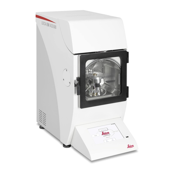
Introduction The Leica EM ACE600 coating system is used for precise coating of samples for subsequent examination with an electron microscope (EM). Up to two angled sources can be configured. Automated stage rotation is integrated for best distribution. Integrated quartz crystal measurement accurately determines the layer thickness Automated height and tilt adjustment is optional, otherwise tilt and height are set manually. -
Page 10: Safety
The housing must not be opened except by an authorized Leica representative. If the Leica EM ACE600 coating system is damaged or malfunctions, all use of the system should be suspended until the malfunction or damage has been corrected. - Page 11 Caution There is a danger of electric shock when the housing is removed. Injuries may be sustained that could lead to death. The Leica EM ACE600 coating system must not be operated unless all covers are properly in place. Caution! Some of the components inside the system may become hot and present a danger of injury.
-
Page 12: Instrument Overview
6. Touch sensitive control panel 7. Adjustable feet 8. Chamber door 9. USB port 10. Power supply switch 11. Mains power inlet for coater 12. Argon gas inlet 13. Nitrogen gas inlet Operating Manual Leica EM ACE600 Version 06/15 Page 8... -
Page 13: Installation And Set Up
The Leica EM ACE600 has to be set up on a stable laboratory workbench with a surface area of at least 680mm depth and 450 mm width. -
Page 14: Unpacking And Connection
2.3. Unpacking and connection The Leica EM ACE600 coating system should be transported with a forklift truck. Lift up the outer box. Remove top foam lid. Operating Manual Leica EM ACE600 Version 06/15 Page 10... - Page 15 11. Torx key and brush for the carbon thread head 12. Bayonette ring for sputter target 13. Shutters Remove accessory box and all protection foam material, then remove the inner framing upwards. Operating Manual Leica EM ACE600 Version 06/15 Page 11...
- Page 16 (packaging provides recess for hands) and place it on a table. Two strong people are required to lift the coater! Place the EM ACE600 on a stable bench. Adjusted all feet and counter lock (flat spanner 13 mm) to maintain level and stable positioning.
- Page 17 This can help to reduce the pump down time. Regulate argon pressure to ~0.5 bar over atmosphere. We strongly recommend using a two-stage pressure regulator on the argon bottle. Operating Manual Leica EM ACE600 Version 06/15 Page 13...
-
Page 18: Inserting Chamber Shielding
Take out the main shielding and unscrew the screw on the top middle of the chamber shielding which holds the part to separate and close the gap between the two shutters. Operating Manual Leica EM ACE600 Version 06/15 Page 14... - Page 19 Put in a glass shield. (Or take out the coated round glass and replace it with a new one). Put the metal bar back to its spot and screw it on gently. Operating Manual Leica EM ACE600 Version 06/15 Page 15...
- Page 20 The three plates fit together in the rear of the coater like as shown here: The first shield goes into the right top corner of the rear of the coating chamber. Align hole to the pin on the chamber wall and push on. Operating Manual Leica EM ACE600 Version 06/15 Page 16...
- Page 21 The third shield covers the bottom of the rear of the coating chamber. Make sure the backplates are firmly pushed against the back wall of the coating chamber otherwise the shutter could get stuck. Operating Manual Leica EM ACE600 Version 06/15 Page 17...
-
Page 22: Shutter Installation
Glow discharge cable (4) Screw the shutter into the hole (see picture on previous page) in the middle of the rear of the coating chamber by the thumb screw. Tighten firmly. Operating Manual Leica EM ACE600 Version 06/15 Page 18... - Page 23 Slide the extra packaged shutter spring (1) on to the pin on the shutter (2). *Instrument on this picture equipped with two sources For an instrument with two sources repeat the same for the installation of the second shutter. Operating Manual Leica EM ACE600 Version 06/15 Page 19...
-
Page 24: Quartz Crystal Measurement Installation
2.6. Quartz crystal measurement installation The Leica EM ACE600 is equipped with quartz crystal film thickness measurement (QSG, see 3.6). The QSG equipment for installation includes: - Quartz head with cable (1) - Quartz crystals (2) Unscrew the cover of the quartz holder. - Page 25 Replace the cover and tighten gently. Slide quartz (1) from the top through the hole (2) in the middle of the stage. Push the quartz head down until it firmly sits on the stage. Operating Manual Leica EM ACE600 Version 06/15 Page 21...
- Page 26 When using a holder to mount the quartz on the side of the stage (see images under 3.9), don’t forget to change the settings from quartz on stage to quartz on side as described in 3.1.1 Operating Manual Leica EM ACE600 Version 06/15 Page 22...
-
Page 27: Stage Installation
120° after each pulse (rotation is on). Rotation and flashing a carbon thread is not possible. Cover the connections of the motorized stage with the delivered covers. The motor spindle is covered and secured with a screw. Operating Manual Leica EM ACE600 Version 06/15 Page 23... - Page 28 Motorized stage (1) with table (2) to load up to 24 standard 12,7 mm (1/2”) SEM stubs with a pin diameter of 3.2 mm. The optional table is used for two 76mm x 26mm (3” x 1”) standard glass slides. Operating Manual Leica EM ACE600 Version 06/15 Page 24...
- Page 29 Make sure to always have all planets placed on the planetary drive stage when using it for coating samples. The planets cover and so protect the mechanics from being coated which can lead to friction and so compromised rotation. Operating Manual Leica EM ACE600 Version 06/15 Page 25...
- Page 30 Left image: The thumb screw (1) defines how much force is needed to adjust the tilt. The screw should not be opened for adjusting. Rigth image: Pointer for the scale of the manual stage to adjust the height (each line is 10 mm). Operating Manual Leica EM ACE600 Version 06/15 Page 26...
-
Page 31: Eccentric Quartz Holder
(1) Tilt adjustment, (2) Height adjustment. Eccentric quartz holder When installing the holder to place the quartz on the side of the stage, please make sure it slides into the gap all the way in. Operating Manual Leica EM ACE600 Version 06/15 Page 27... - Page 32 Loosen the screw with an Allen key and lift up the cover slightly, the stage will slide in. Don’t forget to change the quartz settings from stage to side (see 3.1.1). Operating Manual Leica EM ACE600 Version 06/15 Page 28...
-
Page 33: Operation
Operation Touch screen control panel The LCD control panel is used for communicating with the Leica EM ACE600 coating system as well as for data input and output. The parameters for the coating process are edited via the touch screen. -
Page 34: Settings
5. Set the units for pressure (mbar, psi, Torr) and temperature (Celsius, Fahrenheit or Kelvin) The coater is delivered calibrated. If the touch seems to lose its accuracy calibrate the screen. Operating Manual Leica EM ACE600 Version 06/15 Page 30... -
Page 35: Menu
1. Upload, import and export log files ( see also 3.1.3) 2. Edit protocols or sequences ( see also 3.11) 3. Test a quartz (see also 3.6) 4. Access service interface 5. Perform software updates( 3.1.4) Operating Manual Leica EM ACE600 Version 06/15 Page 31... -
Page 36: File Handling
4. Info shows detail of the selected files 5. Warning USB stick is not connected 6. Scroll down the list of log files File information in detail displayed when pushing Info (4): Operating Manual Leica EM ACE600 Version 06/15 Page 32... -
Page 37: Software Update
It is recommended to first update the user interface and then the controller update. The update files need to be on a USB-stick in a folder with the directory Leica/CTupdate. Operating Manual Leica EM ACE600 Version 06/15 Page 33... -
Page 38: Pump And Vent
The vacuum level is visualised using the vacuum bar. On most screens there is a vacuum bar element included to quickly read the vacuum level. Operating Manual Leica EM ACE600 Version 06/15 Page 34... -
Page 39: Vacuum Test
Pressing the “Stop” button will terminate the process (after confirmation) regardless of the step of the process. The system eithers stays under vacuum or vents automatically (vent after process is activated, see section 3.5). Operating Manual Leica EM ACE600 Version 06/15 Page 35... -
Page 40: Vent After Process
Every Leica EM ACE600 system is equipped with the QSG film thickness measurement monitor. The user can choose between termination by QSG and termination by timer. Even when terminating by timer the layer thickness is displayed in the summary of a finished process. - Page 41 The frequency of a new crystal is ~6 MHz and should be stable, when the quartz reaches around 5 MHz it is recommended to exchange it with a new one The last digit can move slightly. Operating Manual Leica EM ACE600 Version 06/15 Page 37...
-
Page 42: Carbon Thread Coating
The resulting thickness is shown in the process summary. For best results and fault free operation only the Leica carbon thread, order number 16LZ02308VN (3.5m) or 16LZ02307VN (25m) should be used. To minimize carbon fibre residues dropping onto the sample we recommend using the “Pulse”... -
Page 43: Loading A Carbon Thread
Fold the thread into half and load it. Make sure the instrument is vented (see 3.2). Open the source cover (1) Unplug the connectors (2) Unscrew the 2 evaporation head screws to remove the flange (3) Operating Manual Leica EM ACE600 Version 06/15 Page 39... - Page 44 Prepare the following parts on a clean desk: Carbon head (1) Torx TX 10 (2) Brush (3) Carbon thread (4) Loosen all 5 clamp screws with the Torx key. Remove any carbon thread residue using the brush supplied. Operating Manual Leica EM ACE600 Version 06/15 Page 40...
- Page 45 At the same time tighten the screw as shown in the picture. Wind the thread around the other clamps. Take care that the thread slides into the clamping groove (1), follow the path: Pull the thread gently and tighten the last clamp. Operating Manual Leica EM ACE600 Version 06/15 Page 41...
- Page 46 If not all screws are tightened the instrument may not recognize the thread section. Clean the sealing surface with a lint-free tissue. There is an EM ACE600 YouTube video where the loading of the thread can be seen: http://www.youtube.com/watch?v=Qj3Y-WfNbvM&feature=relmfu After the carbon thread is loaded, replace the head, gently tighten the fastening screws and connect the cables and close the cover.
-
Page 47: Choosing A Carbon Thread Protocol
Turn on the mains switch at the back of the unit, wait for the start screen (see 3.1) and press The process screen loads (see below). Operating Manual Leica EM ACE600 Version 06/15 Page 43... - Page 48 10. Vacuum bar indicating current vacuum, allows to enable pump and vent (see 3.2) When a sample is especially heat sensitive there is the material “carbon thread low power” available. The evaporation temperature is lower but with increased pulse duration. Operating Manual Leica EM ACE600 Version 06/15 Page 44...
-
Page 49: Running A Carbon Thread Process
3. ‘Venting after coating’ is activated or deactivated. Can be changed at any time 4. Status bar indicating what the instrument is doing at the moment Operating Manual Leica EM ACE600 Version 06/15 Page 45... - Page 50 1. Type: condition to reach is pressure 2. State: process is running 3. Process vacuum: the process vacuum has to be reached to start the process 4. Back to running procedure screen Operating Manual Leica EM ACE600 Version 06/15 Page 46...
- Page 51 5. Vacuum at which the evaporation is performed 6. Method: Either pulse or flash 7. Back to running procedure screen Each thread is degassed separately before it is used. The systems waits after outgassing to stabilize the vacuum. Operating Manual Leica EM ACE600 Version 06/15 Page 47...
- Page 52 11. Chamber light on/off 12. ‘Complete’ to go back to process screen (before option to initialize the system, stage and shutter) 13. Access the menu (see 3.1.2) 14. Restart the same process Operating Manual Leica EM ACE600 Version 06/15 Page 48...
-
Page 53: Sputter Coating
(diffuse means slower rate) and the grain size (directional means finer grains). With the quartz thickness measurement (QSG) the layer thickness can be calculated as a result of the changed quartz crystal resonance frequency (3.6). Targets Various targets can be supplied by Leica Microsystems for the EM ACE600: Gold Gold-Palladium Platinum... -
Page 54: Loading The Sputter Target
Unclean targets can cause plasma instability and therefore abort the process. Only using Leica targets can insure problem-free sputtering. Rotation should be used for the evaporation, only then a homogeneous distribution can be ensured. Termination of sputtering by either time or thickness... -
Page 55: Choosing A Sputtering Protocol
Fix target by gently tightening the bayonet ring. Tighten the ring by hand only. There is an EM ACE600 YouTube video which also shows the loading of the target http://www.youtube.com/watch?v=Qj3Y-WfNbvM&feature=relmfu When the target is secured, replace the sputter head, gently tighten the fastening screws and connect the cable and close the cover. - Page 56 Menu (see 3.1.2. To edit a process see 3.11.2) Start to run the process (see 3.8.3..) Back to start screen (see 3.1) 10 Vacuum bar indicating current vacuum, allows to enable pump and vent (see 3.2). Operating Manual Leica EM ACE600 Version 06/15 Page 52...
-
Page 57: Running A Sputtering Process
3.8.3 Running a sputtering process When a protocol is chosen and/or adjusted the process can be run by pressing button which will turn into a button. Screen of a running sputtering process: Operating Manual Leica EM ACE600 Version 06/15 Page 53... - Page 58 When the sputtering vacuum is reached and stabilized, the high voltage switches on and the plasma starts. Hint, in case vacuum cannot stabilized or plasma is not stable check if the argon line is open. Preconditions details when clicking on the box Operating Manual Leica EM ACE600 Version 06/15 Page 54...
- Page 59 1. Type: condition to reach is pressure 2. State: process is running 3. Process vacuum: the process vacuum has to be reached to start the process 4. Back to running procedure screen Operating Manual Leica EM ACE600 Version 06/15 Page 55...
- Page 60 3. Desired thickness (3 or 4 terminates process, decided before starting) 4. Desired sputter time (4 or 3 terminates process, decided before starting ) 5. Vacuum for sputtering 6. Sputter current 7. Target material 8. Back to running procedure screen Operating Manual Leica EM ACE600 Version 06/15 Page 56...
- Page 61 10. Vacuum bar indicating current vacuum, allows to enable pump and vent (see 3.2) 11. Chamber light on/off 12. ‘Complete’ and option to initialize the system (stage and shutter) 13. Access the menu (see 3.1.2) 14. Restart the same process Operating Manual Leica EM ACE600 Version 06/15 Page 57...
-
Page 62: Ebeam Coating
3.1.1 Grid stage and standard stage with a diameter of 60mm Operating Manual Leica EM ACE600 Version 06/15 Page 58... - Page 63 Standard stage and quartz holder mounted on the EM ACE600 After choosing and starting a protocol for e-beam evaporation the system will perform the following steps automatically (see 3.9.2 and 3.9.3). Pumping Pumping until base vacuum is reached Setting the stage...
-
Page 64: Loading An E Beam Evaporation Source
Make sure the instrument is vented (see 3.2). Open the source cover (1) Unplug the connectors (2) Unscrew the 2 evaporation head screws to remove the flange (3) Prepare the following parts on a clean desk: Operating Manual Leica EM ACE600 Version 06/15 Page 60... - Page 65 8. Allen key size 3 for exchanging the tungsten filament 1. Carbon rods 2. Tungsten filaments 3. Carbon rods for platinum 4. Platinum inlets Place the e-beam source on a clean table. Operating Manual Leica EM ACE600 Version 06/15 Page 61...
- Page 66 Holding ring Aperture e-beam source Use the special tool to unscrew the holding ring. Remove the holding ring. Place the holding ring next to the e-beam source. Operating Manual Leica EM ACE600 Version 06/15 Page 62...
- Page 67 Use the special tool to take out the e-beam source, by screwing it into the thread in the middle. Pull upwords to get the e-beam source out of the housing. Operating Manual Leica EM ACE600 Version 06/15 Page 63...
- Page 68 For easy further operation the e-beam source can be placed into the holding ring. Open the screw to access the filament and target. Turn the Wehnelt cylinder to the other side to open a window. The filament can be seen through this window. Operating Manual Leica EM ACE600 Version 06/15 Page 64...
- Page 69 To adjust the rod, turn the collet holder on the bottom of the e-beam source. To clean the e-beam source without taking it completely apart compressed air (oil and water free!) can be used. Operating Manual Leica EM ACE600 Version 06/15 Page 65...
- Page 70 They are changed when they cannot stabilize the evaporation anymore. To change the rod, the Wehnelt cylinder has to be removed by opening the two screws on the top. Operating Manual Leica EM ACE600 Version 06/15 Page 66...
- Page 71 Take out the screws and ceramic insulator. Lift up the Wehnelt cylinder. Carbon rod (1) inside the tungsten filament (2) can be seen. Operating Manual Leica EM ACE600 Version 06/15 Page 67...
- Page 72 If the carbon rod gets stuck in the collet there is a pin available to push it out from the back side. To prepare a carbon rod take a new rod and cut it in half. Operating Manual Leica EM ACE600 Version 06/15 Page 68...
- Page 73 Use a razor blade to score the middle. After scoring the surface… ….it can be broken in half. Operating Manual Leica EM ACE600 Version 06/15 Page 69...
- Page 74 To prepare a carbon platinum rod, take a new 2mm carbon rod with recess and a platinum inlet. Some carbon cement, a tooth pick or similar and forceps are needed. Operating Manual Leica EM ACE600 Version 06/15 Page 70...
- Page 75 Apply some carbon cement… Make sure to work fast, the cement dries very quickly. … and put the platinum pellet in. Clean the squeezed out cement with a tissue. Operating Manual Leica EM ACE600 Version 06/15 Page 71...
- Page 76 When changing from carbon evaporation to platinum or the other way round, the collet is screwed out of the collet holder. Ususlly this can be done by hand. In case it is too tight the wrench number 5 is used. Operating Manual Leica EM ACE600 Version 06/15 Page 72...
- Page 77 Take the prepared rod and push it into the collet. Fix the rod with the collet ring. Operating Manual Leica EM ACE600 Version 06/15 Page 73...
- Page 78 Remove the old filament and place the centering rod in the hole in the middle. Take a new coil, slide it over the centering rod and mount it with the two clamping plates. Try to avoid tension in the filament. Operating Manual Leica EM ACE600 Version 06/15 Page 74...
- Page 79 When the tungsten coil is fixed, take out the centering rod. Tungsten coil and target are loaded. Make sure the ceramic insulators are in place before mounting the aperture. Operating Manual Leica EM ACE600 Version 06/15 Page 75...
- Page 80 Put the Wehnelt cylinder on top and fix it with the two screws. Don’t use much force to tighten the screws it can break the ceramic insulators! Make sure the window is closed Operating Manual Leica EM ACE600 Version 06/15 Page 76...
- Page 81 Do not thighten the holding ring. There is a risk it will get stuck when heating up. Replace the e-beam source on the coater, gently tighten the fastening screws and connect the cables and close the cover. Operating Manual Leica EM ACE600 Version 06/15 Page 77...
-
Page 82: Choosing An E Beam Protocol
8. Start the evaporation process (see 3.9.4) 9. Back to start screen (see 3.1) 10. Switch degassing of for this run 11. Vacuum bar indicating current vacuum, allows to enable pump and vent (see 3.2) Operating Manual Leica EM ACE600 Version 06/15 Page 78... -
Page 83: Running An E Beam Process
Current coating rate Accumulated thickness (value in brackets: final thickness to be reached) 6. Stopping the process at any time after confirming to stop Process is finished, summary screen is displayed: Operating Manual Leica EM ACE600 Version 06/15 Page 79... - Page 84 11. Access the menu (see 3.1.2) 12. Restart the same process Parameter suggestion e-beam coating: Carbon Denisity: 2,25 g/cm3 Quarz: 15 Hz/nm Degassing: 75W (1,5kV / 50mA) / 5min Evaporation: 150W (1,8kV / 80mA) / Operating Manual Leica EM ACE600 Version 06/15 Page 80...
-
Page 85: Carbon Rod Coating
5. Carbon rod sharpener 6. Copper clamps for carbon rod 7. Special holding tool for the carbon rod clamps 8. Special tool to hold the carbon rod for sharpening 9. Carbon rods Operating Manual Leica EM ACE600 Version 06/15 Page 81... -
Page 86: Loading A Carbon Rod
Unscrew the two evaporation head screws (1) to remove the cover (2) The evaporation head (3) stays mounted in the instrument, it is only removed for extended cleaning For regular cleaning, loose particles are removed with the brush Operating Manual Leica EM ACE600 Version 06/15 Page 82... - Page 87 4. Copper clamps for carbon rod 5. 2,5 allen key 6. Carbon rod sharpener 7. Special tool to hold the carbon rod for sharpening 8. Special holding tool for the carbon rod clamps Operating Manual Leica EM ACE600 Version 06/15 Page 83...
- Page 88 Turn the carbon rod holder in circles until the top is sharp. Flatten the tip to about 1 mm diameter. This will allow an exact positioning against the flat rod for evaporation. Operating Manual Leica EM ACE600 Version 06/15 Page 84...
- Page 89 On the shorter side (1) mount the flat rod, aligned with the edge of the recess. On the longer side (2) mount the pointy rod, the tip aligned with the edge. Operating Manual Leica EM ACE600 Version 06/15 Page 85...
- Page 90 When taking out a rod to exchange and/or sharpen it, open the screw (1) and push down. The clamp will open and the rod can be easily taken out. Use the special tool to keep the carbon rod evaporation source (spring loaded) open. Operating Manual Leica EM ACE600 Version 06/15 Page 86...
- Page 91 When the second rod is mounted in the same way the tool which keeps the evaporation source open is removed (1). The two rods should push against each other (2). Operating Manual Leica EM ACE600 Version 06/15 Page 87...
- Page 92 Wipe around the sealing surface with a lint free tissue and ethanol Reattach the source cover, tighten the evaporation head screws and close the cover. Operating Manual Leica EM ACE600 Version 06/15 Page 88...
-
Page 93: Choosing A Carbon Rod Protocol
7. Menu (see 3.1.2. To edit a process see 3.13) 8. Start the evaporation process (see 3.10.3) 9. Back to start screen (see 3.1) 10. Vacuum bar indicating current vacuum, allows to enable pump and vent (see 3.2) Operating Manual Leica EM ACE600 Version 06/15 Page 89... -
Page 94: Running A Carbon Rod Process
Status (either idle, process or venting) b. Time since start button was pushed (value in brackets: time since protocol started) c. Current coating rate 6. Stopping the process at any time after confirming to stop Operating Manual Leica EM ACE600 Version 06/15 Page 90... - Page 95 It may deviate slightly from the reading dislplayed during the deposition because the radiation influence on the quartz is fluctuating with several parameters and can, therefore, be only approximated. Operating Manual Leica EM ACE600 Version 06/15 Page 91...
-
Page 96: Glow Discharge
Turn on the mains switch at the back of the unit Start screen will appear. Press on To use the glow discharge option, ensures that the glow discharge electrode is mounted. The glow discharge screen loads (see below). Operating Manual Leica EM ACE600 Version 06/15 Page 92... - Page 97 1. Current: glow discharge current 2. Ar: working vacuum (note: for glow discharge air is used) 3. Working distance:the distance of sample surface to source 4. Tilt: Angle of the table to the horizontal Operating Manual Leica EM ACE600 Version 06/15 Page 93...
-
Page 98: Running A Glow Discharge Process
‘waiting’ elements to pause between two processes can be placed. Turn on the mains switch at the back of the unit, wait for the Start screen (see 3.1) and press on The sequence main screen loads (see below). Operating Manual Leica EM ACE600 Version 06/15 Page 94... - Page 99 8. Details of the chosen sequence and option to start running the sequence (see below) When a sequence is chosen and/or adjusted the sequence can be run by pressing the button which will turn into a button. Operating Manual Leica EM ACE600 Version 06/15 Page 95...
- Page 100 3. Sputter process with the protocol for Platinum 4. Precondition for next protocol 5. Sputter process with protocol for Tungsten 6. Scroll bar to see following protocols 7. Stop sequence, confirmation required follows Operating Manual Leica EM ACE600 Version 06/15 Page 96...
- Page 101 8. Vacuum bar indicating current vacuum, allows to enable pump and vent <t any time (see 3.2) 9. Chamber light on/off 10. Complete and option to initialize the system (stage and shutter) 11. Access the menu (see 3.1.2) 12. Restart the same process Operating Manual Leica EM ACE600 Version 06/15 Page 97...
-
Page 102: Editing A Protocol Or Sequence
On the top of the screen is a panel with buttons for the following actions: 1. Adding a new protocol 2. Deleting the displayed protocol 3. Editing the displayed protocol 4. Copying the displayed protocol to edit it Operating Manual Leica EM ACE600 Version 06/15 Page 98... - Page 103 3. Set a tilt, minus is left, plus is right 4. Rotation 1-5, maximum is 20rpm 5. Pressing the pre-set button will move the stage to values, set between 1-4 Operating Manual Leica EM ACE600 Version 06/15 Page 99...
- Page 104 3. Set the thickness(only for pulse mode) 4. Enable if double thread is used By pushing the save button the edited protocol is chosen and the process can be run by pushing the start button (see 3.7.3). Operating Manual Leica EM ACE600 Version 06/15 Page 100...
-
Page 105: Editing A Sputtering Process
For either adding or editing a protocol the following parameters are set: Tab ‘Profile’: 1. Set a name for the protocol 2. Option for further description of the protocol 3. Drop down menu to choose the material Operating Manual Leica EM ACE600 Version 06/15 Page 101... - Page 106 3. Set a tilt, minus is left, plus is right 4. Rotation 1-5, maximum is 20 rpm 5. Pressing the pre-set button will move the stage to values set between 1.- 4. Operating Manual Leica EM ACE600 Version 06/15 Page 102...
- Page 107 Argon is bled in for 10 seconds and then pumped for 30 seconds. Tab ‘Sputtering’: 1. Set the sputter current 2. Define a thickness limit 3. Define a time limit 4. Sputter source is in the right or left (facing the instrument) Operating Manual Leica EM ACE600 Version 06/15 Page 103...
- Page 108 (3.8.2). The reproducibility of using the QSG and therefore a termination by thickness is more accurate than a termination by time. Operating Manual Leica EM ACE600 Version 06/15 Page 104...
-
Page 109: Editing An E Beam Process
This is important for low angle rotary shadwoing. OR put in the desired effective coating anlge (3) and the instrument automatically sets the stage tilt to coat under that angle. Rotation can be set 1 to 5 (2). Operating Manual Leica EM ACE600 Version 06/15 Page 105... - Page 110 Working distance is the the vertical line form the horizontal table to the Wehnelt cylinde. The effective coating angle can be between 1° and 90°. The vacuum which needs to be reached before starting e-beam coating is defined. Operating Manual Leica EM ACE600 Version 06/15 Page 106...
- Page 111 Press save and the evaporation can be started By pushing the save button the edited protocol is chosen and the process can be run by pushing the start button (see 3.9.3). Operating Manual Leica EM ACE600 Version 06/15 Page 107...
-
Page 112: Editing A Carbon Rod Process
(for details see beginning chapter 3.12). Preset materials are either carbon with or without degassing. Geometrical settings (details see 3.12.1). Operating Manual Leica EM ACE600 Version 06/15 Page 108... - Page 113 (set in the materials file) the deposition is terminated and a message is displayed on the screen. By pushing the save button the edited protocol is chosen and the process can be run by pushing the start button (see 3.10.3). Operating Manual Leica EM ACE600 Version 06/15 Page 109...
-
Page 114: Editing A Glow Discharge Process
4. Copying the displayed protocol For either adding or editing a protocol the following parameters are set: Tab ‘Profile’: 1. Set a name for the protocol 2. Option for further description of the protocol Operating Manual Leica EM ACE600 Version 06/15 Page 110... - Page 115 5. Pressing the pre-set button will move the stage to values, set between 1-4 Tab ‘Vacuum’: 1. Set the vacuum for the glow discharge process 2. Enable or disable vent after process (see 2.5) Operating Manual Leica EM ACE600 Version 06/15 Page 111...
-
Page 116: Editing A Sequence
On the top of the screen is a panel with buttons for the following actions: 1. Adding a new sequence 2. Deleting the selected sequence 3. Editing the selected sequence 4. Copying the selected sequence 5. Selected sequence Operating Manual Leica EM ACE600 Version 06/15 Page 112... - Page 117 Tap on the process and select an existing protocol out of the list. To move a chosen process (1) tap on it, select move on the top of the screen and move it with the arrows which appear (2). Operating Manual Leica EM ACE600 Version 06/15 Page 113...
-
Page 118: Manual Stage: Difference In User Interface And Set Up
Tilt and height of the stage have to be set manually. The instrument calculates the stage settings: Lift height is the increase from the lowest position of the stage (e.g.: set the stage 16mm above the lowest position). Operating Manual Leica EM ACE600 Version 06/15 Page 114... -
Page 119: Defining A Coating Material
On the top of the screen is a panel with buttons for the following actions: 1. Adding a new material 2. Deleting the chosen material 3. Editing the chosen material 4. Copying chosen material Operating Manual Leica EM ACE600 Version 06/15 Page 115... -
Page 120: Define A Carbon Thread
Set name, an abbreviation if necessary. New materials can always be edited. The screenshots show a pre-set material which can not be edited. Set the parameters for the degassing process (heat current, heat voltage and heat time). Operating Manual Leica EM ACE600 Version 06/15 Page 116... - Page 121 The flash voltage can be adjusted to desired value. The Factor is characteristic for carbon. It indicates how much (Hz) the frequency of the quartz crystall changes with 1nm applied material. Operating Manual Leica EM ACE600 Version 06/15 Page 117...
-
Page 122: Define A Sputter Target
(true). The screenshots show a pre-set material which can not be edited. Density is the specific weight (g/m3) of the material. Set if pre-sputtering is required. Set the pre-sputtering current and time. Operating Manual Leica EM ACE600 Version 06/15 Page 118... -
Page 123: Define An E Beam Target
3.14.3 Define an e-beam target Following screens show the parameters which can be set for the material when editing or defining one. Set name, an abbreviation if necessary. New materials can always be edited (true). Operating Manual Leica EM ACE600 Version 06/15 Page 119... -
Page 124: Define A Carbon Rod Material
3.14.4 Define a carbon rod material Following screens show the parameters which can be set for the material when editing or defining one. Set name, an abbreviation if necessary. New materials can always be edited (true). Operating Manual Leica EM ACE600 Version 06/15 Page 120... - Page 125 Density is the specific weight (g/m3) of the material. Set if preheating is required. The factor is used for the QSG thickness measurement and calculated from the specific weight of the material but it can be overwritten. Operating Manual Leica EM ACE600 Version 06/15 Page 121...
- Page 126 Set the parameters for the degassing process (voltage and time). Minimum and maximum voltage are the range of voltage covered within the rise time see 3.13.4) Operating Manual Leica EM ACE600 Version 06/15 Page 122...
-
Page 127: Maintenance And Service
When working on the vacuum chamber or parts which are in the vacuum chamber of the Leica EM ACE600 coating system it is essential to follow the principles of vacuum hygiene. Gloves must be worn when disassembling and assembling components in the vacuum area, and also for all adjustment work. -
Page 128: Source Cover
Thin threads can peel off the anode ring and cause a short circuit. Extensive cleaning and parameter check is recommended once a year by a trained Leica service engineer to ensure flawless operation. Recommendation Usually, only the glass door needs to be cleaned, depending on the layer thicknesses coated and the visibility needs. - Page 129 Occasionally, it can happen that an elongated flake builds up by the sputtered material. This can cause a shirt circuit which will be indicated by a warning when starting a sputtering process. Clean the anode ring by wiping with ethanol. Operating Manual Leica EM ACE600 Version 06/15 Page 125...
- Page 130 The LCD control panel should be cleaned with standard commercial screen cleaner when the system is switched off Accidental spillage of solvents (e.g. acetone, isopropanol or ethanol) must be removed immediately with a damp, lint-free cloth moistened with aqueous cleaning agents Operating Manual Leica EM ACE600 Version 06/15 Page 126...
-
Page 131: Removing The Door
Place the door flat on a soft surface to clean. There are screws to hold the glass. The complete glass can be exchanged by unscrewing both screws on the side to hold the glass. Replace the glass and tighten the screws again. Operating Manual Leica EM ACE600 Version 06/15 Page 127... -
Page 132: Removing Shutter And Internal Shielding
To exchange the glass shielding for the chamber light please refer to 2.4. Before first use please install a glass shielding. When the chamber light becomes too dark, the shieling for the light can be easily exchanged. Operating Manual Leica EM ACE600 Version 06/15 Page 128... -
Page 133: Troubleshooting
Remedy the coating chamber Error Yellow warning sign next to vacuum bar. Possible cause Cover or door handle is open Remedy Close cover or door handle properly then the sign disappears Operating Manual Leica EM ACE600 Version 06/15 Page 129... -
Page 134: Error Messages
Error messages Leica EM ACE600 – Hint/Error/Warning List Code Title Message (Text) Description System (Panel) Specific: System halted due to an Softare crash (exception handling) E0000 Error unexpected error\nRestart > Restart software immediately. system No controller communication Controller comm. established. Check status LED... - Page 135 Process terminated\nQuartz frequency before process has to unstable.\nChange quartz to Process be stable to quarantee valid E1303 guarantee \nvalid measurement -> Change quartz in measurement case and try to run process again Operating Manual Leica EM ACE600 Version 06/15 Page 131...
- Page 136 Process stopped - All threads exhausted in process, but still W4002 Warning All threads exhausted some pulses to proceed (or thickness not reached) > Abort process Operating Manual Leica EM ACE600 Version 06/15 Page 132...
- Page 137 Check target and sputter source. deposited solid material on shutter Process terminated\nIgnition fault\nCheck argon Process aborted - Unable to E2010 Process flow\nCheck target and establish plasma ignition. sputter source Operating Manual Leica EM ACE600 Version 06/15 Page 133...
- Page 138 E8002 temperature\nCheck N2 reference temperature timeout dewar empty E-Beam Controller Specific Process aborted - Could not E-Beam supply already E9001 Warning switch on power due power is still switched on active Operating Manual Leica EM ACE600 Version 06/15 Page 134...
- Page 139 Evaporation supply already E5000 Warning switch on power due power is still switched on active Process terminated\nReference Process aborted - Invalid E5001 Process voltage incorrect\nSet valid parameter (voltage) sent parameter and try again Operating Manual Leica EM ACE600 Version 06/15 Page 135...
- Page 140 -> Short circuit or change rod source mounting. Process aborted - Communication Process response timeout occurred -> E5012 Process terminated\nOperation Unable to stabilize or comm. Error response timeout -> Restart device Operating Manual Leica EM ACE600 Version 06/15 Page 136...
-
Page 141: Servicing And Repair
Servicing and repair The Leica EM ACE600 is covered by a WARRANTY according to the conditions of sale. If functional errors should occur or if the components of the system sustain damage that is subject to warranty coverage during the warranty period, the manufacturer will repair or replace the faulty components following examination thereof. -
Page 142: Technical Data Sheet
Leica EM ACE600 Technical Data Sheet Version 03/15... - Page 143 Leica EM ACE600 High Vacuum Coater LEICA EM ACE600 - BASIC UNIT LEICA EM ACE600 - WITH VCT CONNECTION OPERATIONAL AND GENERAL DATA Ultimate vacuum ≤ 2x10 mbar** Ultimate vacuum with Meissner trap ≤ 7x10 mbar** Pumping time to 5x10 mbar approx.
- Page 144 TECHNICAL DATA SHEET – LEICA EM ACE600 OPERATIONAL AND GENERAL DATA Leica thread (usable as singel or double, ~0.25 g/m), 4 sections, Carbon thread pulsed or flashed evaporation Carbon rod 3 mm diamter carbon: 3 mm rod (max. rate 0.3 nm/s), platinum/carbon: 2 mm rod...
-
Page 145: Ec Declaration Of Conformity
Hernalser Hauprstrasse 219 A-1170 Wien, Austria declare in exclusive resposibility that the product erklären in alleiniger Verantwortung, dass das Produkt déclarons sous notre responsabilité que le produit Model Leica EM ACE600 Modell Leica EM ACE600 modèle Leica EM ACE600 Type/Typenbezeichnung/type... - Page 146 CONNECT WITH US! Leica Mikrosysteme GmbH · Hernalser Hauptstrasse 219 · A-1170 Wien T +43 488 99 · F +43 48899-350 www.leica-microsystems.com...
Need help?
Do you have a question about the EM ACE600 and is the answer not in the manual?
Questions and answers