Table of Contents
Advertisement
Advertisement
Table of Contents

Related Manuals for Leica EM ACE600


Summary of Contents for Leica EM ACE600
- Page 1 From Eye to Insight OPERATING MANUAL EM ACE600 167202032 Version 01/19...
- Page 2 Important Note Leica Mikrosysteme GmbH reserves the right to change technical specifications as well as manufacturing processes without prior notice. Only in this way is it possible to con- tinuously improve the technology and manufacturing techniques used to provide our customers with excellent products.
- Page 3 Leica EM ACE600 Operating Manual Leica EM ACE600 Serial Number: Date of purchase: For the instrument serial number, please refer to the name type label on the back of the instrument! Please read this instruction manual carefully before operating the instrument.
- Page 5 Users must familiarize themselves with the system before operation. Special attention must be paid to comply with the safety requirements. The Leica EM ACE600 must not be used beyond the limits specified in the provided technical data sheet.
-
Page 6: Table Of Contents
4.5 Thickness monitoring and geometrical correction (QSG) ........... 45 4.6 Carbon thread coating ....................46 4.6.1 Loading a carbon thread ....................47 4.6.2 Choosing a carbon thread protocol ................... 51 Operating Manual Leica EM ACE600 Version 01/19 Page 2... - Page 7 5.1 General instructions for maintenance and cleaning ..........110 5.1.1 Source cover ........................111 5.2 Cleaning of the Leica EM ACE600 ................111 5.2.1 Removing and cleaining the door with a metal polisher ..........115 5.2.2 Removing shutter and internal shielding .................
-
Page 9: Introduction
Introduction In order to ensure the safety of operators and service technicians, and to prevent any damage to the Leica EM ACE600, it is essential to read this manual carefully before beginning to work with the system. This user manual is intended to provide the user a complete understanding of the system (including its specified limits and capabilitites), as well as to maintain and service it in accordance with its physical parameters. - Page 10 Danger of pinching the fingers when closing the flange (stage). Hot surface during and right after processing the sample. Allow to cool before servicing the ion source. Operating Manual Leica EM ACE600 Version 01/19 Page 5...
-
Page 11: Identification
Identification 1.1.1 Product Leica EM ACE600 High Vacuum Coater 1.1.2 Name and address of the manufacturer Leica Mikrosysteme GmbH Hernalser Hauptstraße 219 A-1170 Vienna Tel.: +43 1 488 99-0 Fax: +43 1 488 99-350 Internet: www.leica-microsystems.com... -
Page 12: Product Description
Product description Field of application and proper use The Leica EM ACE600 coating system is used for precise coating of samples for subsequent examination with an electron microscope (EM). Up to two angled sources can be configured. Automated stage rotation is integrated for best distribution. -
Page 13: Dimensions And Weight
Instrument packed app. 74 kg Note: e-beam instruments are about 20 mm more in depth and 5 kg heavier. Dimensions for the Leica EM ACE600 with a VCT500 are in the technical data sheet and the manual for cryo outfits. -
Page 14: Safety Information
All electrical parts are safely separated from the user by the front cover and back housing. If the Leica EM ACE600 coating system is damaged or malfunctions, all use of the system should be suspended until the issue has been corrected. -
Page 15: Safety Measures At The Installation Site
Repairs may only be made by Leica authorized service staff or authorized representatives. If the Leica EM ACE600 coating system is installed incorrectly, the system may be damaged and may incur injury to the user Maintenance and Service may only be conducted by technicians authorised only by the manufacturer's service department. -
Page 16: Safety Measures When Working With Nitrogen
Glass Dewars often burst for no obvious reason or due to unintentional mishandling (e.g. contact with metal instruments etc.). Never work without open protective glasses when using LN in a glass Dewar. Operating Manual Leica EM ACE600 Version 01/19 Page 11... - Page 17 , since only containers of this kind exclude risks during storage. For routine cryopreparation metal troughs (1 cm Styrofoam insulation), Styrofoam containers or plastic troughs are eminently suitable and ensure low risk cryopreparation. Operating Manual Leica EM ACE600 Version 01/19 Page 12...
- Page 18 Unplug the instrument before installing or changing fuses. Operating Manual Leica EM ACE600 Version 01/19 Page 13...
- Page 19 Dewars in confined spaces Burns boils at -196 °C. It is extremely cold and can cause serious burns. Please read the safety instructions provided with all Leica products for the correct handling of liquid nitrogen! Operating Manual Leica EM ACE600 Version 01/19...
-
Page 20: Emergency Procedure
3.1. Warranty The Leica EM ACE600 is covered by a WARRANTY according to the conditions of sale. If functional errors should occur or if the components of the system sustain damage that is subject to warranty coverage during the warranty period, the manufacturer will repair or replace the faulty components following examination thereof. -
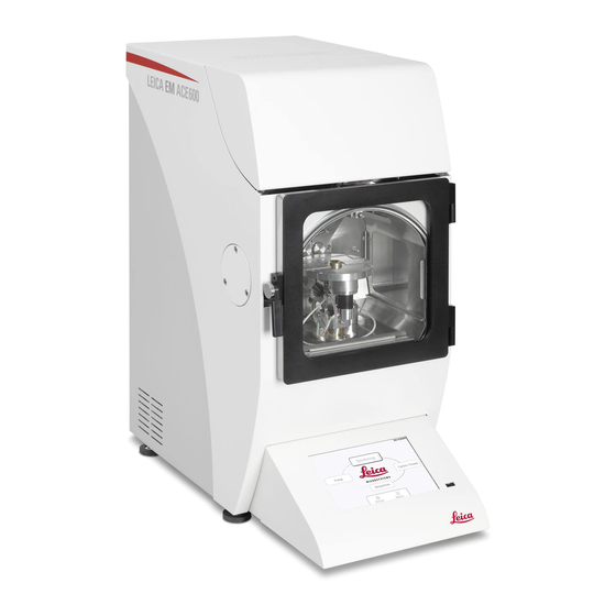
Page 21: Instrument Overview
6. Touch sensitive control panel 7. Adjustable feet 8. Chamber door 9. USB port 10. Power supply switch 11. Mains power inlet for coater 12. Argon gas inlet 13. Nitrogen gas inlet Operating Manual Leica EM ACE600 Version 01/19 Page 16... -
Page 22: Delivery Of The Instrument
When working on the vacuum chamber or parts, which are in the vacuum chamber of the Leica EM ACE600, coating system it is essential to follow the principles of vacuum hygiene. Gloves must be worn when disassembling and assembling components in the vacuum area, and also for all adjustment work. -
Page 23: Unpacking And Connection
3.5. Unpacking and connection The Leica EM ACE600 coating system should be transported with a forklift truck. Lift up the outer box. Remove top foam lid. Operating Manual Leica EM ACE600 Version 01/19 Page 18... - Page 24 11. Torx key and brush for the carbon thread head 12. Bayonet ring for sputter target 13. Shutters Remove the accessory box and all protection foam material, then remove the inner framing upwards. Operating Manual Leica EM ACE600 Version 01/19 Page 19...
- Page 25 (packaging provides recess for hands) and place it on a table. Two strong people are required to lift the coater! Place the Leica EM ACE600 on a stable bench. Adjusted all feet and counter lock (flat spanner 13 mm) to maintain level and stable positioning.
- Page 26 This can help to reduce the pump down time. Regulate argon pressure to ~0.5 bar over atmosphere. We strongly recommend using a two-stage pressure regulator on the argon bottle. Operating Manual Leica EM ACE600 Version 01/19 Page 21...
-
Page 27: Inserting Chamber Shielding
Take out the main shielding and unscrew the screw on the top middle of the chamber shielding which holds the part to separate and close the gap between the two shutters. Operating Manual Leica EM ACE600 Version 01/19 Page 22... - Page 28 Put in a glass shield. (or take out the coated round glass and replace it with a new one). Put the metal bar back to its spot and screw it on gently. Operating Manual Leica EM ACE600 Version 01/19 Page 23...
- Page 29 The three plates fit together in the rear of the coater like as shown here: The first shield goes into the right top corner of the rear of the coating chamber. Align hole to the pin on the chamber wall and push on. Operating Manual Leica EM ACE600 Version 01/19 Page 24...
- Page 30 The third shield covers the bottom of the rear of the coating chamber. Make sure the back plates are firmly pushed against the back wall of the coating chamber otherwise the shutter could be stuck. Operating Manual Leica EM ACE600 Version 01/19 Page 25...
-
Page 31: Shutter Installation
Glow discharge connection (3) Glow discharge cable (4) Screw the shutter into the hole (see picture on previous page) in the middle of the rear of the coating chamber by the thumbscrew. Tighten firmly. Operating Manual Leica EM ACE600 Version 01/19 Page 26... - Page 32 Slide the extra packaged shutter spring (1) on to the pin on the shutter (2). *Instrument on this picture equipped with two sources For an instrument with two sources, repeat the same for the installation of the second shutter. Operating Manual Leica EM ACE600 Version 01/19 Page 27...
-
Page 33: Quartz Crystal Measurement Installation
3.8. Quartz crystal measurement installation The Leica EM ACE600 is equipped with quartz crystal film thickness measurement. The QSG equipment for installation includes: - Quartz head with cable (1) - Quartz crystals (2) 1 2 Unscrew the cover of the quartz holder. - Page 34 Slide quartz (1) from the top through the hole (2) in the middle of the stage. 1 2 Push the quartz head down until it firmly sits on the stage. Quartz is placed correctly on the stage. Operating Manual Leica EM ACE600 Version 01/19 Page 29...
-
Page 35: Eccentric Quartz Holder
3.8.1 Eccentric quartz holder When installing the holder to place the quartz on the side of the stage, please make sure it slides into the gap all the way in. Operating Manual Leica EM ACE600 Version 01/19 Page 30... - Page 36 Note for sputter processes. When using the side settings for the quartz Argon pressure of 2x10⁻² to 9x10⁻³ mbar or lower should be used for the sputtering. Above the measurement is less accurate. Operating Manual Leica EM ACE600 Version 01/19 Page 31...
-
Page 37: Stage Installation
Cover the connections of the motorized stage with the delivered covers. The motor spindle is covered and secured with a screw. Operating Manual Leica EM ACE600 Version 01/19 Page 32... - Page 38 Motorized stage (1) with table (2) to load up to 24 standard 12.7 mm (1/2”) SEM stubs with a pin diameter of 3.2 mm. 2 1 The optional table is used for two 76 mm x 26 mm (3” x 1”) standard glass slides. Operating Manual Leica EM ACE600 Version 01/19 Page 33...
- Page 39 It is important to always have all planets placed on the planetary drive stage when coating samples. The planets cover and therefore protect the mechanics from being coated, which can lead to friction and compromised rotation. Operating Manual Leica EM ACE600 Version 01/19 Page 34...
-
Page 40: Rotating Stage
Left image: The thumbscrew (1) defines how much force is needed to adjust the tilt. The screw should not be opened for adjusting. Right image: Pointer for the scale of the rotating stage to adjust the height (each line is 10 mm). 2 1 Operating Manual Leica EM ACE600 Version 01/19 Page 35... - Page 41 Stage on the lowest position equals to a source distance of 100 mm. (1) Tilt adjustment, (2) Height adjustment. 1 2 Operating Manual Leica EM ACE600 Version 01/19 Page 36...
-
Page 42: Operating Instructions
Operating instructions Touch screen control panel The LCD control panel is used for communicating with the Leica EM ACE600 coating system as well as for data input and output. The parameters for the coating process are edited via the touch screen. -
Page 43: General Functions
Update (5) is used when a software update is performed. The light button (6) operates the chamber light and the Service button (7) gives access to the service environment asking for a password. This area is reserved for Leica authorized personnel. - Page 44 All stored processes can be exported onto a USB stick and be imported back to the instrument from a USB stick. Operating Manual Leica EM ACE600 Version 01/19 Page 39...
- Page 45 (specific weight of carbon and the parameters for pulsing or flashing method). Tap on a line for copying or editing the material. The pre-set material is locked, only new ones can be edited. Operating Manual Leica EM ACE600 Version 01/19 Page 40...
- Page 46 1 nm of platinum refers to around 145 Hz. If a side quartz is used it has to be set accordingly on this screen, otherwise the thickness calculation is wrong. Operating Manual Leica EM ACE600 Version 01/19 Page 41...
-
Page 47: Software Update
Enter the menu, connect a USB stick to the port on the touch screen panel and press update. Choose from the list which updates shall be performed by pushing the respective button on the select update column. Operating Manual Leica EM ACE600 Version 01/19 Page 42... - Page 48 It is required to first update the user interface and then the required controllers. The update files need to be on a USB-stick in a folder with the directory Leica/CTupdate. Operating Manual Leica EM ACE600 Version 01/19 Page 43...
-
Page 49: Pump And Vent
(faster adjusting of the sputter vacuum). The vacuum level is visualised using the vacuum bar. On most screens there is a vacuum bar element included to quickly read the vacuum level. Operating Manual Leica EM ACE600 Version 01/19 Page 44... -
Page 50: Vacuum Test
Every Leica EM ACE600 system is equipped with the QSG film thickness measurement monitor. The user can choose between termination by QSG and Operating Manual Leica EM ACE600... -
Page 51: Carbon Thread Coating
The resulting thickness is shown in the process summary. For best results and fault free operation, only the Leica carbon thread should be used (16771511116). To minimize carbon fiber residues dropping onto the sample we recommend using the “Pulse”... -
Page 52: Loading A Carbon Thread
Open the source cover (1) Unplug the connectors (2) Unscrew the 2 evaporation head screws to remove the flange (3) 1 2 3 Prepare the following parts on a clean desk: Operating Manual Leica EM ACE600 Version 01/19 Page 47... - Page 53 Do not brush off the threads close to the instrument. Use a bin well a side and placed on the floor. This avoids fibers to reach the inside of the instrument. Operating Manual Leica EM ACE600 Version 01/19 Page 48...
- Page 54 Take care that the thread slides into the clamping groove (1), follow the path: Pull the thread gently and tighten the last clamp. Tighten the remaining 3 screws and trim thread on both ends. Operating Manual Leica EM ACE600 Version 01/19 Page 49...
- Page 55 Clean the sealing surface with a lint-free tissue. There is a Leica EM ACE600 YouTube video where the loading of the thread can be seen: http://www.youtube.com/watch?v=Qj3Y-WfNbvM After the carbon thread is loaded, replace the head, gently tighten the fastening screws and connect the cables and close the cover.
-
Page 56: Choosing A Carbon Thread Protocol
Select a protocol by tapping on it. Once it is marked, by tapping on a specific category, the parameters can be changed. Alternatively, a protocol can be copied and then modified or a new one added. Operating Manual Leica EM ACE600 Version 01/19 Page 51... - Page 57 Rotation can be either set to continuous or a 120° turn after each pulse (1). Settings can be checked by pushing the Test button. Init stops the testing and moves the stage to the init position. Operating Manual Leica EM ACE600 Version 01/19 Page 52...
-
Page 58: Carbon Thread Materials
(adjusting current and voltage accordingly). Time between the pulses and duration of a pulse is defined. Flash current and voltage are a limit. The flash voltage can be adjusted to desired value. Operating Manual Leica EM ACE600 Version 01/19 Page 53... -
Page 59: Sputter Coating
With the quartz thickness measurement (QSG) the layer thickness can be calculated because of the changed quartz crystal resonance frequency (3.8). Targets Various targets can be supplied by Leica Microsystems for the EM ACE600 for example: Gold Gold-Palladium ... -
Page 60: Loading The Sputter Target
Starting the sputtering process by opening the shutter and starting rotation (if set to rotate) Unclean targets can cause plasma instability and therefore abort the process. Only using Leica targets can insure problem-free sputtering. Rotation should be used for the evaporation, only then a homogeneous distribution can be ensured. ... - Page 61 Fix target by gently tightening the bayonet ring. Tighten the ring by hand only. There is a Leica EM ACE600 YouTube video which also shows the loading of the target http://www.youtube.com/watch?v=Qj3Y-WfNbvM When the target is secured, replace the sputter head, gently tighten the fastening screws and connect the cable and close the cover.
-
Page 62: Choosing A Sputtering Protocol
Select a protocol by tapping on it. Once it is marked, by tapping on a specific category, the parameters can be changed. Alternatively, a protocol can be copied and then modified or a new one added. Operating Manual Leica EM ACE600 Version 01/19 Page 57... - Page 63 Rotation speed can be set from 1 to 5 (equals to 20 rpm) Settings can be checked by pushing the Test button. Init stops the testing and moves the stage to the initial position, such as abandoning the edit stage screen. Operating Manual Leica EM ACE600 Version 01/19 Page 58...
- Page 64 The sputter vacuum will be reached much faster in this way. Purge cycles: Argon is let in for 10 seconds and then pumped for 30 seconds. Sputter material: Operating Manual Leica EM ACE600 Version 01/19 Page 59...
-
Page 65: Parameters For Sputter Coating
In case the vacuum or plasma cannot be stabilized, check if the argon line is open. 4.7.4 Sputter materials New sputter materials can be defined. Open Menu, tab file and material management. Select an existing material or add a new one. Operating Manual Leica EM ACE600 Version 01/19 Page 60... -
Page 66: E-Beam Coating
When using a LARS or grid stage for low angle rotary shadowing with the quartz mounted on a holder on the side of the stage, do not forget to change the settings from quartz on stage to quartz on side as described in 4.1. Operating Manual Leica EM ACE600 Version 01/19 Page 61... - Page 67 Grid stage and standard stage with a diameter of 60 mm: Standard stage and quartz holder mounted on the EM ACE600 After choosing and starting a protocol for e-beam evaporation the system will perform the following steps automatically (see 3.9.2 and 3.9.3).
-
Page 68: Loading An E-Beam Evaporation Source
Open the source cover (1) Unplug the connectors (2) Unscrew the 2 evaporation head screws to remove the flange (3) 1 2 3 Prepare the following parts on a clean desk: Operating Manual Leica EM ACE600 Version 01/19 Page 63... - Page 69 8. Allen key size 3 for exchanging the tungsten filament 2 3 4 1. Carbon rods 2. Tungsten filaments 3. Carbon rods for platinum 4. Platinum inlets Place the e-beam source on a clean table. Operating Manual Leica EM ACE600 Version 01/19 Page 64...
- Page 70 Holding ring e-beam source Use the special tool to unscrew the holding ring. Remove the holding ring and place the holding ring next to the e-beam source. Operating Manual Leica EM ACE600 Version 01/19 Page 65...
- Page 71 For easy further operation, the e-beam source can be placed into the holding ring. Open the screw to access the filament and target. The filament can be seen through this window. Operating Manual Leica EM ACE600 Version 01/19 Page 66...
- Page 72 The tip of the carbon rod should be in the middle of the coil. Same for the platinum tip. To adjust the rod, turn the collet holder on the bottom of the e-beam source. Operating Manual Leica EM ACE600 Version 01/19 Page 67...
- Page 73 Filaments are not changed preventively; their lifetime varies a lot. They are changed when they cannot stabilize the evaporation anymore. Operating Manual Leica EM ACE600 Version 01/19 Page 68...
- Page 74 To change the filament, the Wehnelt cylinder has to be removed by opening the two screws on the top. Take out the screws and lift up the Wehnelt cylinder. Carbon rod (1) inside the tungsten filament (2) can be seen. Operating Manual Leica EM ACE600 Version 01/19 Page 69...
- Page 75 To change the carbon rod, screw out the collet holder. If the carbon rod is stuck in the collet, there is a pin available to push it out from the back side. Operating Manual Leica EM ACE600 Version 01/19 Page 70...
- Page 76 To prepare a carbon rod take a new rod and cut it in half. Use a razor blade to score the middle. After scoring the surface… ….it can be broken in half. Operating Manual Leica EM ACE600 Version 01/19 Page 71...
- Page 77 Method 1: Take some pliers and bend the round platinum into a slightly oval shape. Then put the inlet into the carbon rod. If bent enough the inlet stays in the rod. Operating Manual Leica EM ACE600 Version 01/19 Page 72...
- Page 78 Method 2: Take some fibers of a carbon thread and place them on the platinum pellet. Push the carbon rod on the pellet. Some fibers will stick out. Operating Manual Leica EM ACE600 Version 01/19 Page 73...
- Page 79 Method 3: Glue the pellet with some carbon cement into the carbon rod. A tooth pick or similar and forceps are needed. Apply some carbon cement… Operating Manual Leica EM ACE600 Version 01/19 Page 74...
- Page 80 When changing from carbon evaporation to platinum or the other way round, the collet is screwed out of the collet holder. Usually this can be done by hand. In case it is too tight, the wrench number 5 is used. Operating Manual Leica EM ACE600 Version 01/19 Page 75...
- Page 81 Operating Manual Leica EM ACE600 Version 01/19 Page 76...
- Page 82 Take the prepared rod and push it into the collet. Fix the rod with the collet ring. To exchange the tungsten filament loosen the two screws clamping the filament down. Operating Manual Leica EM ACE600 Version 01/19 Page 77...
- Page 83 When the tungsten coil is fixed, take out the centering rod. Screw in the collet holder with the carbon rod. Tungsten coil and target are loaded. Make sure the spacers are in place before mounting the aperture. Operating Manual Leica EM ACE600 Version 01/19 Page 78...
- Page 84 Make sure the window is closed Screw in the rod to hold the e-beam source, align the pins of housing and e-beam source and put the e-beam source into the housing. Operating Manual Leica EM ACE600 Version 01/19 Page 79...
-
Page 85: Choosing An E-Beam Protocol
There, the parameters for the process can be changed and saved. Only thickness can be adjusted on the process screen (3). Once everything relevant for the coating process is defined, the process can be started (4). 1 2 3 4 Operating Manual Leica EM ACE600 Version 01/19 Page 80... - Page 86 Stage allows setting a coating angle or tilt of the stage. When setting a coating angle, the tilt is automatically calculated or vice versa. The working distance is kept constant. Continuous rotation from 1-5 can be set (5 equals to 20 rpm). Operating Manual Leica EM ACE600 Version 01/19 Page 81...
-
Page 87: Parameter Suggestion E-Beam Coating
Density: 19.45 g/cm3 Quartz: 130 Hz/nm Outgassing (melting in): 50W (1,0kV / 50mA) / 2min Evaporation: 100W (1,6kV / 60mA) / Carbon should be operated between 90-150 W, Platinum between 60-100 W. Operating Manual Leica EM ACE600 Version 01/19 Page 82... -
Page 88: E-Beam Material
New e-beam materials can be defined. Open Menu, tab file and material management. Select an existing material or add a new one. Density is the specific weight (g/m ) of the material. Set if degassing power and time. Operating Manual Leica EM ACE600 Version 01/19 Page 83... -
Page 89: Carbon Rod Coating
After choosing and starting a protocol for carbon rod evaporation the system will perform the following steps automatically (see 3.10.3). Pumping Pumping until base vacuum is reached Setting the stage Operating Manual Leica EM ACE600 Version 01/19 Page 84... -
Page 90: Loading A Carbon Rod
In case, it can be easily adjusted by hand. For regular cleaning, loose particles are removed with the brush 1 2 3 Prepare the following parts on a clean desk: Operating Manual Leica EM ACE600 Version 01/19 Page 85... - Page 91 8. Special holding tool for the carbon rod clamps To prepare a carbon rod, take a new rod and cut it in half (approximately). Use a razor blade to score the middle. After scratching the surface … Operating Manual Leica EM ACE600 Version 01/19 Page 86...
- Page 92 Turn the carbon rod holder in circles until the top is sharp. Flatten the tip to about 1 mm diameter. This will allow an exact positioning against the flat rod for evaporation. Operating Manual Leica EM ACE600 Version 01/19 Page 87...
- Page 93 On the shorter side (1) mount the flat rod, aligned with the edge of the recess. On the longer side (2) mount the pointy rod, the tip aligned with the edge. Operating Manual Leica EM ACE600 Version 01/19 Page 88...
- Page 94 When taking out a rod to exchange and/or sharpen it, open the screw (1) and push down. The clamp will open and the rod can be easily taken out. 1 Use the special tool to keep the carbon rod evaporation source (spring loaded) open. Operating Manual Leica EM ACE600 Version 01/19 Page 89...
- Page 95 When the second rod is mounted in the same way the tool, which keeps the evaporation source, open is removed (1). The two rods should push against each other (2). 1 2 Operating Manual Leica EM ACE600 Version 01/19 Page 90...
-
Page 96: Choosing A Carbon Rod Protocol
In the library of recipes (1) all stored protocols are available and can be chosen. Tapping on the characteristics of the protocol (2) opens the list of recipes. There the parameters for the process can be changed and saved. Operating Manual Leica EM ACE600 Version 01/19 Page 91... - Page 97 4.9.3). If the quartz is not used it will be evaporated for the set time with the minimum voltage (5,2V). Pre-heat (= degassing process) is performed or not (3). Operating Manual Leica EM ACE600 Version 01/19 Page 92...
- Page 98 Settings can be checked by pushing the Test button. Init stops the testing and moves the stage to the init position. A vacuum is set which needs to be reached before the coating process starts (=base vacuum) Operating Manual Leica EM ACE600 Version 01/19 Page 93...
-
Page 99: Carbon Rod Materials
Alternatively, a material can be copied and then modified or a new one added. The default materials are locked and cannot be overwritten (2). 2 1 Screenshot for the parameters under Method. Operating Manual Leica EM ACE600 Version 01/19 Page 94... -
Page 100: Glow Discharge
Only time can be adjusted on the process screen (3). Once everything relevant for the coating process is defined, the process can be started (4). Operating Manual Leica EM ACE600 Version 01/19 Page 95... - Page 101 Select a protocol by tapping on it. Once it is marked, by tapping on a specific category, the parameters can be changed. Alternatively, a protocol can be copied and then modified or a new one added. Operating Manual Leica EM ACE600 Version 01/19 Page 96...
- Page 102 1 to 5 (equals to 20 rpm). Settings can be checked by pushing the Test button. Init stops the testing and moves the stage to the init position. Operating Manual Leica EM ACE600 Version 01/19 Page 97...
-
Page 103: Sequence
All protocols of the library can be combined to a sequence. Additionally, ‘waiting’ elements to pause between two processes can be placed. On the main screen press open sequence. Operating Manual Leica EM ACE600 Version 01/19 Page 98... - Page 104 Select a protocol for a sequence by tapping on it. Once it is marked by tapping on the name or included processes, the details can be changed. Alternatively, a sequence can be copied and then modified or a new one added. Operating Manual Leica EM ACE600 Version 01/19 Page 99...
- Page 105 The total sequence can run over several screens (change by button 1). 1 Tapping on add, a new process can be implemented into the sequence. First the method is selected, then the specific protocol and then the position in the sequence. Operating Manual Leica EM ACE600 Version 01/19 Page 100...
- Page 106 1 2 Mark a step in the sequence to modify it. Tapping on an already implemented process allows changing the process itself or moving the position. Operating Manual Leica EM ACE600 Version 01/19 Page 101...
-
Page 107: Rotating Stage: Difference In User Interface And Set-Up
Rotating stage: difference in user interface and set-up Rotating stage is indicated in the stage editing screen (1). It is important to set the height and tilt before starting the process. 1 Operating Manual Leica EM ACE600 Version 01/19 Page 102... -
Page 108: Running A Process
Tapping on the process box (Carbon in this case) shows the most important parameters of that process. Operating Manual Leica EM ACE600 Version 01/19 Page 103... - Page 109 While the sample is coated the average coating rate (1) as well as the current thickness (2) and the thickness to be achieved (3) is displayed. 1 2 3 Operating Manual Leica EM ACE600 Version 01/19 Page 104...
- Page 110 It may deviate slightly from the reading displayed during the deposition because the radiation influence on the quartz is fluctuating with several parameters and can, therefore, be only approximated. Operating Manual Leica EM ACE600 Version 01/19 Page 105...
-
Page 111: Load Lock
VCT holders (up to four) have to be used to transfer the sample into the coater with the load lock. Mount the VCT holder carrying the sample on the load lock manipulator tip (1). 1 Attach the load lock to the dock. Loaded sample. Operating Manual Leica EM ACE600 Version 01/19 Page 106... - Page 112 (2) allows adjusting the pump and purging time of the load lock as well as closing and removing the cover of the VCT dock. Push load lock (3) to attach the load lock, open the gate valve and transfer the sample. Operating Manual Leica EM ACE600 Version 01/19 Page 107...
- Page 113 In case the stage must be aligned to transfer the VCT holders push Adjust and align height (1), angle (2) and tilt (3). Set will save the values for the respective position. 1 2 3 Operating Manual Leica EM ACE600 Version 01/19 Page 108...
- Page 114 After placing all the samples (up to four), the load lock manipulator has to be pulled out. It is recommended to close the gate valve after finishing load lock manipulation. With the button Vent, the gate valve is closed. Operating Manual Leica EM ACE600 Version 01/19 Page 109...
-
Page 115: Maintenance And Service
When working on the vacuum chamber or parts, which are in the vacuum chamber of the Leica EM ACE600, coating system it is essential to follow the principles of vacuum hygiene. Gloves must be worn when disassembling and assembling components in the vacuum area and for all adjustment work. -
Page 116: Source Cover
If the source cover closes too quickly, it is possible to tighten the hinges using a 3 mm Allen key. Be careful not to over tighten. Cleaning of the Leica EM ACE600 The internal shielding, shutter including the glow discharge electrode and the anode ring should be cleaned or replaced when: ... - Page 117 Cleaning material There is a Leica cleaning product available for parts used in vacuum, which is the ideal solution for cleaning: 16771511205. If not by hand, alternatively, metal cleaning paste works well. Scotch brite should only be used on metal parts. Do not use any abrasives on the glass door because scratches can lead to small leaks.
- Page 118 Clean the anode ring by wiping with ethanol. Carbon thread head The ceramic plate (1) on the carbon thread head is cleaned with a brush each time exchanging the threads. This surface must not have continuous carbon layer. Operating Manual Leica EM ACE600 Version 01/19 Page 113...
- Page 119 1 2 Housing All surfaces can be cleaned with a damp, lint-free cloth moistened with either aqueous cleaning agents or 50% ethanol (ethanol - water 1:1) Do NOT use ACETONE! Operating Manual Leica EM ACE600 Version 01/19 Page 114...
-
Page 120: Removing And Cleaining The Door With A Metal Polisher
Scratches could cause a vacuum leak. The complete glass can be exchanged by unscrewing both screws on the side to hold the glass. Replace the glass and tighten the screws again. Operating Manual Leica EM ACE600 Version 01/19 Page 115... -
Page 121: Removing Shutter And Internal Shielding
To exchange the glass shielding for the chamber light please refer to 3.6. Before first use, please install a glass shielding. When the chamber light becomes too dark, the shieling for the light can be easily exchanged. Operating Manual Leica EM ACE600 Version 01/19 Page 116... -
Page 122: Troubleshooting
Troubleshooting Leica EM ACE600 – Hint/Error/Warning List Code Title Message (Text) Description System (Panel) Specific: System halted due to an Software crash (exception E0000 Error unexpected error, Restart handling) > Restart software system immediately. No controller communication Controller comm. Error, established. - Page 123 Valves and Device For Leaks Side Stage, Working W0019 Warning Distance Lower than 80 mm HiVac Controller Specific: Quartz not detected. Warning only W1300 Warning No quartz detected active in debug mode. Operating Manual Leica EM ACE600 Version 01/19 Page 118...
- Page 124 Check cover sensor. head (1) not connected, Process aborted - Specific head E1902 Process Connect cable not connected! head (2) not connected, Process aborted - Specific head E1903 Process Connect cable not connected! Operating Manual Leica EM ACE600 Version 01/19 Page 119...
- Page 125 Process - aborted. Mains supply Process terminated, mains voltage out of range (<85 V)! E2002 Process supply voltage out of range Check if right voltage is delivered <85 V by the network Operating Manual Leica EM ACE600 Version 01/19 Page 120...
- Page 126 Anyway? Glow discharge specific: Process aborted - Short-circuit Process terminated, Short because of invalid assembly of E2109 Process circuit in glow-discharge, plates. Check deposited solid Check shutter panels material on shutter Operating Manual Leica EM ACE600 Version 01/19 Page 121...
- Page 127 E1401 Stage Initialization Timeout! VCT Transfer Terminated Process E1402 Stage Position Incorrect! Process Dock Not Closed E1403 Process Dock Not Open E1404 Process Shuttle Not Closed E1405 Operating Manual Leica EM ACE600 Version 01/19 Page 122...
- Page 128 Process aborted - Invalid E9002 Warning Set valid parameter and try parameter (voltage) sent again Invalid current value, Set Process aborted - Invalid E9003 Warning valid parameter and try again parameter (current) sent Operating Manual Leica EM ACE600 Version 01/19 Page 123...
- Page 129 E5001 Process Set valid parameter and try parameter (voltage) sent again Process terminated, Reference current incorrect, Process aborted - Invalid E5002 Process Set valid parameter and try parameter (current) sent again Operating Manual Leica EM ACE600 Version 01/19 Page 124...
- Page 130 Loss) Source Exhausted (Short E5010 Process Circuit) Process aborted - Communication Process terminated, response timeout occurred -> E5012 Process operation response timeout Unable to stabilize or comm. Error -> Restart device Operating Manual Leica EM ACE600 Version 01/19 Page 125...
- Page 131 (RoHS directive) 2011/65/EU (RoHS Richtlinie) Vienna/Wien/Vienna, 21/07/2017 Dr. Paul Wurzinger Entwicklungsleiter/R&D Manager/Chef du service développment Leica Mikrosysteme GmbH · Hernalser Hauptstrasse 219 · A-1170 Wien T +43 1 48899 0 · F +43 1 48899 350 CONNECT www.leica-microsystems.com WITH US!
- Page 132 CONNECT WITH US! Leica Mikrosysteme GmbH | Vienna, Austria T +43 1 486 8050-0 | F +43 1 486 8050-30 www.leica-microsystems.com...
Need help?
Do you have a question about the EM ACE600 and is the answer not in the manual?
Questions and answers
need service password to reset timer