Piazzetta P962 Instructions For Installation, Use And Maintenance Manual
Hide thumbs
Also See for P962:

Related Manuals for Piazzetta P962


Summary of Contents for Piazzetta P962
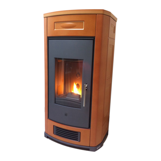
- Page 1 All manuals and user guides at all-guides.com Pellet Stove P962 INSTRUCTIONS FOR INSTALLATION, USE AND MAINTENANCE...
- Page 2 This document is the property of Gruppo Piazzetta S.p.A.; it may not be divulged in part or in whole to third parties without written permission from Gruppo Piazzetta S.p.A. Gruppo Piazzetta S.p.A. reserves all its statutory rights.
-
Page 3: Table Of Contents
DT2010097-03 7.13 Extraordinary maintenance DT2011179-00 TROUBLESHOOTING DT2010557-02 Replacing the fuses DT2010380-04 Declaration of conformity Pellet Stove P962 DT2010383-02 Declaration of conformity Transceiver unit Multicomfort DT2010382-05 European Regulations This booklet code H07021560 / DT2000318 Rev. 00 (01/2008) comprises 56 pages. CONTENTS... -
Page 4: General Rules
All manuals and user guides at all-guides.com DT2010216-04 1.0 GENERAL RULES Ensure that the installation of your product conforms to all the indications given below. Fig. 1 CHIMNEY STACK SINGLE FLUEWAY OR CHIMNEY CONNECTION TO FLUE SOOT INSPECTION APERTURE FRESH AIR INTAKE END ELBOW WITH INSPECTION WINDOW MINIMUM SAFETY DISTANCES... - Page 5 It is forbidden to pass other air ducts or service pipes inside the flue pipe, however large it is. If the flue pipe is an incorrect size or installed other than in compliance with the above instructions, Gruppo Piazzetta Deposit of Creosote DT2030050-00 DT2030188-00 S.p.A.
-
Page 6: Chimney Stack
All manuals and user guides at all-guides.com DT2010025-01 1.3 CHIMNEY STACK - Fig. 7 / 11 The chimney stack is a device fitted on the top of the chimney that is designed to aid dispersion of the products of combustion in the atmosphere. Fig. - Page 7 All manuals and user guides at all-guides.com DT2010026-00 1.4 FRESH AIR INTAKE - Fig. 12 / 15 The stove/fireplace must have the necessary air available to ensure Fig. 12 Fig. 13 proper combustion. - Make sure that the room in which the stove/fireplace is to be installed has an air intake of at least the size indicated in the paragraph “TECHNICAL DATA”.
-
Page 8: Installation Environment
All manuals and user guides at all-guides.com DT2010215-02 1.5 INSTALLATION ENVIRONMENT The appliance must be installed in a location which allows safe and convenient use as well as easy maintenance. If the product being installed requires an electrical socket, the room must also be provided with an earthed power supply in accordance with current regulations. Do not install a wood-burning appliance in a bedroom, bath or shower room or in any room where another heating system not equipped with its own air supply (fireplace, stove etc.) has already been installed. -
Page 9: Minimum Safety Distances
All manuals and user guides at all-guides.com DT2010536-02 1.8 MINIMUM SAFETY DISTANCES - Fig. 16 / 18 First of all decide the exact position for installation of the stove. Fig. 16 Check the minimum safe distances from heat sensitive or inflammable Parete posteriore Rear wall materials, from load bearing and other walls and also from wooden... - Page 10 It must also permit periodic cleaning of the flue without the need to disassemble the pipes. This type of fitting can be bought at Piazzetta retail outlets together with the pipes.
-
Page 11: Connecting To A Conventional Chimney
150 mm. It is also recommended that you insulate the chimney flue (Fig. 21-22). Pipes and bends made by Gruppo Piazzetta S.p.A. are recommended for connection to the flueway, since they are sized to fit the flue outlet of the appliance. -
Page 12: Using An External Flue
All manuals and user guides at all-guides.com DT2010232-02 1.11 USING AN EXTERNAL FLUE - Fig. 23 Fig. 23 An external flue can be used provided it complies with the following requirements: - use only insulated stainless steel pipes (double-lined) fixed to the outside wall of the building (Fig. -
Page 13: Technical Characteristics And Specifications
“MULTICOMFORT”), front hot air outlet at bottom with two baffles to separate flow, two outlets at rear for ducting if required (see section “MULTIFUOCO SYSTEM”) Humidifier: stainless steel, contains 100 cl water DT2010988-00 2.2 TECHNICAL DATA UNIT P962 Nominal thermal power (max/min) 12 / 3.5 Hourly fuel consumption (max/min) kg/h 2.68 / 0.85 Efficiency >... -
Page 14: Product Identification Data
If the rating plate is missing, has been removed or tampered with, any installation and maintenance operations are made difficult due to lack of product identification. In the event of damage, please ask the Piazzetta after-sales service centre for a copy. Production identification... -
Page 15: Wiring Diagram
All manuals and user guides at all-guides.com DT2030375-02 2.5 WIRING DIAGRAM SPEED2 SPEED1 FAN2 FUMI SCAM. COC. ACC. DT2030375-05 SCHEMA ELETTRICO P961 DT2030375 Pos. Key to parts Pos. Key to parts N° Key to colours White Emergency display Power supply with fuse (5X20 4AH250V) Antenna Smoke sensor Yellow-green... -
Page 16: Fuel
Pellets should be stored in a sheltered, dry place. you use high-quality pellets. Gruppo Piazzetta S.p.A has tested and programmed its stoves and can To use good quality pellets with dimensions and heat-producing properties ensure best performance and trouble-free operation using pellets with... -
Page 17: Installation
5.0 INSTALLATION Pursuant to current regulations on the safety of electrical equipment, you must contact a Piazzetta After-Sales Service Centre or a qualified electrician for all and any work connected with installation, maintenance or servicing that involves access to electrical parts. - Page 18 All manuals and user guides at all-guides.com Fig. 29 Fig. 28 Instructions for redirecting heat • The fan system which expels heat into the atmosphere is equipped with two Y-shaped devices which effectively allow the air flow to be doubled up, directing it via a flexible pipe to the back of the stove from where it can then be directed into adjoining rooms.
- Page 19 All manuals and user guides at all-guides.com Fig. 34 SOLUTION 3 - Fig. 34: • The stove is installed in the room to be heated with the heat channelled in three directions. One fan propels heat to both front and rear of the stove via the Ydevice and a length of flexible pipe of diameter 7.5 cm.
-
Page 20: Electrical Connection And The Room Sensor Connection
(fig. 41). Only authorised personnel should carry out this operation. DT2030076-00 Installation can be carried out with any type of room thermostat COLLEGAMENTO SONDA AMBIENTE P962 COLLEGAMENTO CAVO DI ALIMENTAZIONE P962 DT2031444 but requires a PG7 cable gland similar to that shown in fig. 44. To DT2031445 1 Thermostat. -
Page 21: Installing The Y Connector (Optional)
All manuals and user guides at all-guides.com DT2010148-03 5.4 INSTALLING THE Y CONNECTOR (OPTIONAL) - Fig. 47 / 55 Fig. 47 Fig. 48 • The redirection of heat to adjoining rooms is at the user’s left fan discretion. • The Y-connector can be attached to either fan. •... -
Page 22: Use
All manuals and user guides at all-guides.com DT2010992-00 6.0 USE • Do not use the stove as a cooking appliance. • Ensure that the room in which the stove is installed is sufficiently well ventilated (fresh air intake). • Ensure that all joints in the flue are hermetically sealed using a silicone- (not cement-) based sealant which is resistant to temperatures of up to 250ºC and which shows no sign of deterioration. -
Page 23: Lighting For The First Time
All manuals and user guides at all-guides.com NUMBER KEY / DISPLAY DESCRIPTION Key ON/OFF Allows you to start up or shut down the stove. Pressing the stand-by key and holding it down (for around 5 seconds) until KEYPAD BLOCKED Key STAND-BY appears on the display will disable the keypad. - Page 24 All manuals and user guides at all-guides.com STARTUP Action Function Display A cycle starts with three phases which take the stove into the normal operating mode: C O N T R O L • CONTROL (first 20 seconds) Fault chech. The lighter (glow plug) activates.
- Page 25 All manuals and user guides at all-guides.com FAILED IGNITION: WHAT TO DO Action Function Display Shut the stove down • the alarm should stop; pressing C L E A N I N G • check the cause of the failed ignition. Always ON/OFF key down for remove any fuel from the grate before starting a several seconds.
- Page 26 MENU according to the settings pre-programmed by Gruppo C L E A N I N G Piazzetta personnel. This operation removes ash deposits B R A Z I E R and other buildups, which would otherwise prevent correct stove operation. The readout "PUL" appears in STOVE STATUS along with the flue gas temperature.
-
Page 27: Control Panel
All manuals and user guides at all-guides.com INTERRUPTION OF POWER SUPPLY Action Function Display In the event of a brief interruption of the electrical current while the stove is in operation, the stove will restart automatically. • The grate cleaning phase activates. C L E A N I N G •... -
Page 28: Setting The Language
All manuals and user guides at all-guides.com DT2010469-03 6.6 SETTING THE LANGUAGE 1. open the flap on the remote control; S E L E Z I O N E 2. press the “MENU” key; L I N G U A 3. -
Page 29: Programming
All manuals and user guides at all-guides.com DT2010247-05 6.7 PROGRAMMING The remote control can be used to select the following functions from the main MENU: • SELECT LANGUAGE ENGLISH ITALIANO DEUTSCH FRANCAIS • SET CLOCK Remote Control 1-DAY MONDAY 2-DAY TUESDAY 3-DAY WEDNESDAY MENU 4-DAY THURSDAY... - Page 30 All manuals and user guides at all-guides.com SET CLOCK (current day/time) Function Action Display S E T Press the MENU key, select the SET CLOCK menu Set the day using the SELECT MENU key, then confirm by C L O C K pressing the SET key.
-
Page 31: Timer
All manuals and user guides at all-guides.com DT2010242-05 6.8 TIMER The timer allows the user to programme the stove to start up and shut down automatically without any manual intervention. Daily, weekly and weekend programmes can be selected with a maximum of two operating cycles in two separate timetable bands. For example: Cycle 1: from 6am until 9am Cycle 2: from 8.30pm until 11pm... - Page 32 All manuals and user guides at all-guides.com Function Action Display S T A R T Press SELECT MENU to set the startup time, Set startup time for MENU advancing in ten-minute jumps (for example, you P R O G R A M 1st operating cycle.
- Page 33 All manuals and user guides at all-guides.com PROGRAM WEEK Function Action Display S E T Press the MENU key. Using the SELECT MENU Select set chrono key select the SET CHRONO menu and confirm by MENU C H R O N O menu pressing the SET key.
- Page 34 All manuals and user guides at all-guides.com Function Action Display S E T Press SELECT MENU to set the desired power Set desired power for (for example you want power setting 1). Confirm MENU first operating cycle. P O W E R by pressing the SET key.
- Page 35 All manuals and user guides at all-guides.com Function Action Display Press the SELECT MENU key and select on to MENU enable the weekend programme or oFF to disable E N A B L E the weekend programme. Confirm by pressing the Enable or disable SET key.
- Page 36 All manuals and user guides at all-guides.com Function Action Display Press SELECT MENU to set the desired fan desired S E T MENU speed (for example, you want fan speed setting 1). Multifuoco fan speed Confirm by pressing the SET key. V E N T - 1 for first operating When programming the timer on the stove it is not...
-
Page 37: Multicomfort
All manuals and user guides at all-guides.com DT2010251-03 6.9 MULTICOMFORT The pellet stove is fitted with the Multicomfort function. This works in conjunction with the Multifuoco ventilation system to improve heat distribution. It allows the room temperature to be read from the stove or from the remote control, so that the Multifuoco settings can be varied according to the requirements of the rooms to be heated. - Page 38 All manuals and user guides at all-guides.com ENABLE BEEP (audio signal) This function allows you to engage or disengage the alarm signal emitted by the stove to indicate that it has received the remote control's commands. Function Action Display E N A B L E Press the MENU key.
-
Page 39: Modifying The Transmission Unit
All manuals and user guides at all-guides.com DT2010248-04 6.10 MODIFYING THE TRASMISSION UNIT Should two pellet stoves of the same model be installed close to each other and the remote control beam activates both simultaneously, it is possible to modify the transmission unit when the stove has been shut down by taking the following steps: SELECT UNIT Function Action... -
Page 40: Safety Devices
All manuals and user guides at all-guides.com DT2010994-00 6.12 SAFETY DEVICES During operation some parts of the stove (door, handle, ceramic parts) can reach high temperatures. Remember to maintain the safety distances indicated previously. Be careful, take all due precautions and always comply with the instructions. If during operation smoke leaks from any part of the stove or the flue, shut the stove down immediately and ventilate the room. - Page 41 All manuals and user guides at all-guides.com PELLET HOPPER HOUSING TEMPERATURE Sensor Description Display Located on the pellet hopper, its function is to prevent excessive temperature ranges. WHEN ACTIVATED If the pellet hopper temperature reaches critical Thermostat with levels, the thermostat cuts off the power supply to automatic reset the fuel-loading auger, thereby stopping the S A F E T Y...
- Page 42 All manuals and user guides at all-guides.com FLUE GAS TEMPERATURE SENSOR Sensor Description Display Connected to the electronic board, it constantly monitors the working temperature allowing the stove to be used in all safety. WHEN ACTIVATED If the temperature exceeds the fixed safety limit the board cuts off the power supply to the fuel- loading auger thus depriving the grate of pellets S A F E T Y...
-
Page 43: Opening The Door
During operation the door must remain closed. It is to be opened only when the stove has been shut down and cooled for the carrying out of maintenance. DT2010993-00 6.14 HUMIDIFIER FOR STOVE P962 - Fig. 61 Fig. 61 A humidifier tank is a standard part of the stove and is fitted inside the stove at the top under the grille in front of the pellet hopper. -
Page 44: Maintenance
7.0 MAINTENANCE Pursuant to current regulations on the safety of electrical equipment, you must contact a Piazzetta After-Sales Service Centre or a qualified electrician for all and any work connected with installation, maintenance or servicing that involves access to electrical parts. -
Page 45: Cleaning The Smoke Chamber
All manuals and user guides at all-guides.com DT2010159-04 7.4 CLEANING THE SMOKE CHAMBER - Fig. 66 / 68 Fig. 66 Fig. 67 Once a year clean the smoke chamber as follows: • Remove the screw which secures the smoke chamber closing element, then lift the element slightly and remove it by pulling it towards you. -
Page 46: Replacing The Window
The stove is fitted with a 4mm thick glass panel, resistant to thermal shock up to 750ºC; the glass can only be broken by heavy impact or misuse. Do not slam the door or hit the window. In case of breakage replace only with a Gruppo Piazzetta spare part. To replace, proceed as follows: •... -
Page 47: Troubleshooting
All manuals and user guides at all-guides.com DT2011179-00 8.0 TROUBLESHOOTING Some of the problems indicated below may be resolved by following the instructions. All work must be carried out when the appliance is cold and disconnected from the electricity supply (pull out the plug). Authorised qualified persons must be contacted, in accordance with current regulations, whenever it is necessary to work on parts inside the cladding or the firebox in order to resolve the problem. - Page 48 A A L L F F 2 2 " " stove status Check the electrical connections (contact No power supply to the auger a Piazzetta After-Sales Service Centre or an authorised person). Thermal cutout Blocked flue Check and clean the flue A A L L C C "...
- Page 49 Empty the pellet hopper; check and Pellet-charging system blocked clean the auger and chute This instruction booklet contains all the necessary information for installation, operation and maintenance. Only call the Gruppo Piazzetta S.p.A. service centre after having scrupulously followed all the instructions. TROUBLESHOOTING...
-
Page 50: Replacing The Fuses
All manuals and user guides at all-guides.com DT2010557-02 8.1 REPLACING THE FUSES Fig. 70 Electronic board fuse. Fan card Motherboard Unscrew the cartridge fuse or safety plug from the electronic board and replace with a similar one. Motherboard fuse type: F4AL250V Fan card fuse type: F500MAL250V Cartridge fuse/safety plug Tappo porta fusibile... - Page 51 DECLARATION OF CONFORMITY SUPERIOR ® Il sottoscritto, rappresentante il seguente costruttore The undersigned, representative of the following manufacturer Gruppo Piazzetta S.p.A. Via Montello, 22 31010 Casella D'Asolo (TV) - ITALY DICHIARA che l’apparecchiatura descritta in appresso: DECLARES that the product:...
- Page 52 DECLARATION OF CONFORMITY SUPERIOR ® Il sottoscritto, rappresentante il seguente costruttore The undersigned, representative of the following manufacturer Gruppo Piazzetta S.p.A. Via Montello, 22 31010 Casella D'Asolo (TV) - ITALY DICHIARA che l’apparecchiatura descritta in appresso: DECLARES that the product:...
-
Page 53: European Regulations
All manuals and user guides at all-guides.com EUROPEAN REGULATIONS This product “Stove P962” with Multicomfort has been designed, tested and manufactured according to the European R&TTE Directives 1999/5/EC. Following these Directives, this product can be installed in the following countries:... - Page 54 All manuals and user guides at all-guides.com...
- Page 55 All manuals and user guides at all-guides.com...
- Page 56 All manuals and user guides at all-guides.com Product serial number, to be quoted when requesting service from the Gruppo Piazzetta After-Sales Service Centre. Via Montello, 22 31011 Casella d’Asolo (TV) - ITALY Tel. +39.04235271 - Fax +39.042355178 http://www.piazzetta.it e-mail:infopiazzetta@piazzetta.it...
Need help?
Do you have a question about the P962 and is the answer not in the manual?
Questions and answers