Table of Contents
Advertisement
Quick Links
Advertisement
Table of Contents

Subscribe to Our Youtube Channel
Related Manuals for IEI Technology TANK-820-H61 Series


Summary of Contents for IEI Technology TANK-820-H61 Series
- Page 1 TANK -820-H61 E mbedded S ys tem MODE L : TA NK -820-H61 S eries E mbedded S ys tem with 2nd G eneration Intel® C ore™ des ktop proc es s or, V G A , DV I-I, Two G igabit E thernet, F our US B 2.0, Two US B 3.0, R S -232/422/485, R oHS C ompliant Us er Manual...
- Page 2 TANK -820-H61 E mbedded S ys tem R evis ion Date Version Changes 27 December 2017 2.08 Add Manual Conventions 2 December 2016 2.07 Update the location of CPU_FAN 7 March 2016 2.06 Update Pin Define of RS-232 Serial Port Connector (COM1~COM4, COM7, COM8) Update Pin Define of RS-422/485 Serial Port Connector (COM5, COM6)
- Page 3 TANK -820-H61 E mbedded S ys tem C opyright C OP Y R IG HT NOT IC E The information in this document is subject to change without prior notice in order to improve reliability, design and function and does not represent a commitment on the part of the manufacturer.
- Page 4 TANK -820-H61 E mbedded S ys tem Manual C onventions WAR NING Warnings appear where overlooked details may cause damage to the equipment or result in personal injury. Warnings should be taken seriously. C AUT ION Cautionary messages should be heeded to help reduce the chance of losing data or damaging the product.
-
Page 5: Table Of Contents
TANK -820-H61 E mbedded S ys tem Table of C ontents 1 INTRODUCTION ......................1 1.1 O ........................2 VERVIEW 1.2 M ..................... 3 ODEL ARIATIONS 1.3 F ........................3 EATURES 1.4 T ..................3 ECHNICAL PECIFICATIONS 1.5 F ......................6 RONT ANEL 1.6 R... - Page 6 TANK -820-H61 E mbedded S ys tem 3.7.7 LAN Connectors ....................29 3.7.8 Power Input, 3-pin Terminal Block ..............31 3.7.9 Power Input, 4-pin DIN Connector ..............31 3.7.10 RJ-45 RS-422/485 Serial Ports ..............31 3.7.11 RS-232 Serial Port Connectors ..............33 3.7.12 USB Connectors .....................
- Page 7 TANK -820-H61 E mbedded S ys tem 4.3.4 Ethernet and USB2.0 Connectors (USBLAN1) ..........50 4.3.5 Ethernet and USB2.0 Connectors (USBLAN2) ..........50 4.3.6 Power Connector (PWR2) ................51 4.3.7 Power Connector (PWR1) ................51 4.3.8 RS-232 Serial Port Connector (COM1) ............51 4.3.9 RS-232 Serial Port Connector (COM2) ............
- Page 8 TANK -820-H61 E mbedded S ys tem 5.3.8.1 Serial Port n Configuration ..............70 5.3.9 F81866 Super IO Configuration ..............72 5.3.9.1 Serial Port n Configuration ..............72 5.3.10 F81866 H/W Monitor ..................78 5.3.10.1 Smart Fan Mode Configuration .............. 78 5.3.11 Serial Port Console Redirection ..............
- Page 9 TANK -820-H61 E mbedded S ys tem L is t of F igures Figure 1-1: TANK-820-H61 ......................2 Figure 1-2: TANK-820-H61 Front Panel ..................6 Figure 1-3: TANK-820-H61 Rear Panel ..................7 Figure 1-4: TANK-820-H61 LED Indicators ................... 8 Figure 1-5: HPE-3S6 (2P1E) ......................9 Figure 1-6: HPE-3S7 (1P2E) ......................
- Page 10 TANK -820-H61 E mbedded S ys tem Figure 3-24: DB-9 RS-232 Serial Port Connector ..............34 Figure 3-25: USB Device Connection ..................35 Figure 3-26: VGA Connector .......................36 Figure 3-27: VGA Connector .......................36 Figure 3-28: Power Button ......................37 Figure 3-29: Power Connectors ....................38 Figure 3-30: ACC On: AT Mode ....................39 Figure 3-31: ACC On: ATX Mode ....................39 Figure 3-32: ACC On: Shutdown ....................40...
- Page 11 TANK -820-H61 E mbedded S ys tem L is t of Tables Table 1-1: TANK-820-H61 Model Variations ................. 3 Table 1-2: Technical Specifications ....................5 Table 1-3: LED Indicators Description ..................8 Table 1-4: Supported Signals ......................9 Table 1-5: Rated Voltage and Current ..................10 Table 3-1: RJ-45 Ethernet Connector LEDs ................30 Table 3-2: RJ-45 RS-422/485 Serial Port Pinouts ..............32 Table 3-3: DB-9 Connector Pinouts ....................33...
- Page 12 TANK -820-H61 E mbedded S ys tem Table 4-22: RS-232 Serial Port Connector Pinouts (COM2) .............52 Table 4-23: RS-232 Serial Port Connector Pinouts (COM3) .............52 Table 4-24: RS-232 Serial Port Connector Pinouts (COM4) .............52 Table 4-25: RS-232 Serial Port Connector Pinouts (COM7) .............52 Table 4-26: RS-232 Serial Port Connector Pinouts (COM8) .............53 Table 4-27: RS-422/485 Serial Port Connectors Pinouts (COM5) ..........53 Table 4-28: RS-422/485 Serial Port Connectors Pinouts (COM6) ..........53...
- Page 13 TANK -820-H61 E mbedded S ys tem B IOS Menus BIOS Menu 1: Main ........................59 BIOS Menu 2: Advanced ......................61 BIOS Menu 3: ACPI Configuration ....................61 BIOS Menu 4: RTC Wake Settings ....................62 BIOS Menu 5: TPM Configuration ....................64 BIOS Menu 6: CPU Configuration ....................65 BIOS Menu 7: CPU Configuration ....................66 BIOS Menu 8: IDE Configuration ....................67 BIOS Menu 9: Intel TXT(LT) Configuration .................68...
-
Page 14: Introduction
TANK -820-H61 E mbedded S ys tem C hapter Introduc tion P age 1... -
Page 15: Overview
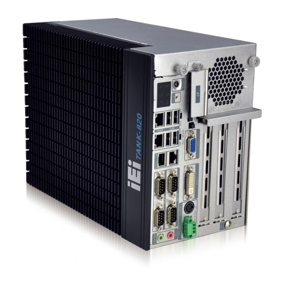
TANK -820-H61 E mbedded S ys tem 1.1 Overview Figure 1-1: TANK-820-H61 The TANK-820-H61 is an embedded system for wide range temperature environments. It is powered by the 2nd Generation Intel® Core™ low power desktop processor, uses the Intel® H61 chipset and has 2.0 GB of DDR3 memory on-board. The TANK-820-H61 series includes one VGA port, one DVI-I port, two GbE LAN ports, four USB 2.0 ports, two USB 3.0 ports, six RS-232 connectors and two RS-422/485 connectors. -
Page 16: Model Variations
TANK -820-H61 E mbedded S ys tem 1.2 Model Variations The model variations of the TANK-820-H61 series are listed below. Model No. Variations Expansion Slots TANK-820-H61-i5/2G/2P1E-R10 Intel® Core™ i5 2xxT Two PCI slots TANK-820-H61-i3/2G/2P1E-R10 Intel® Core™ i3 2xxT One PCIe x16 slot... - Page 17 TANK -820-H61 E mbedded S ys tem S pec ific ations 1 x 204-pin DDR3 SDRAM SO-DIMM slot (Max. to 10G) Memory On-board 2GB DDR3 memory Dual Realtek RTL8111E PCIe GbE controllers with ASF 2.0 support E thernet C ontroller I/O and Indic ators 2 x RJ-45 GbE ports E thernet...
-
Page 18: Table 1-2: Technical Specifications
TANK -820-H61 E mbedded S ys tem S pec ific ations P ower Redundant dual DC input P ower S upply Terminal Block: 9 ~ 24V DC Jack: 9 ~ 24V 19V@3.5A (Intel® Core™ i3-2100 processor with 6GB DDR3 P ower C ons umption memory) without add-on card E nvironmental and Mec hanic al -20°C ~ 60°C with air flow... -
Page 19: Front Panel
TANK -820-H61 E mbedded S ys tem 1.5 F ront P anel The front panel of the TANK-820-H61 has the following features (Figure 1-2): Figure 1-2: TANK-820-H61 Front Panel Connectors and buttons on the front panel include the following: 1 x 4-pin power DC jack for 9 V ~ 24 V power input ... -
Page 20: Rear Panel
TANK -820-H61 E mbedded S ys tem 4 x USB 2.0 ports 1 x Reset button 6 x LED indicators (Section 1.7) 1 x Power button 1 x CompactFlash® Type II socket 1 x VGA port ... -
Page 21: Led Indicators
TANK -820-H61 E mbedded S ys tem 1.7 L E D Indic ators There are several indicators on the rear panel of the TANK-820-H61 as shown in Figure 1-4. Figure 1-4: TANK-820-H61 LED Indicators The descriptions of each LED indicator are listed below. L E D Indic ator Des c ription The current power mode status is AT mode. -
Page 22: Backplane Options
TANK -820-H61 E mbedded S ys tem 1.8 B ac kplane Options The backplane options of the TANK-820-H61 are shown below. Figure 1-5: HPE-3S6 (2P1E) Figure 1-6: HPE-3S7 (1P2E) The supported signals of the backplane slots are listed below. B ac kplane S lot S ignal HP E -3S 6 (2P 1E ) -
Page 23: Table 1-5: Rated Voltage And Current
TANK -820-H61 E mbedded S ys tem +12 V 3.75 A -12 V 0.1 A +3.3 V Table 1-5: Rated Voltage and Current WARNING: The system default power is 120 W. The maximum total power of the backplane to support expansion cards is 45 W. The power of the selected expansion cards can not exceed the max. -
Page 24: Dimensions
TANK -820-H61 E mbedded S ys tem 1.9 Dimens ions The physical dimensions are shown below: Figure 1-7: Physical Dimensions (millimeters) P age 11... -
Page 25: Unpacking
TANK -820-H61 E mbedded S ys tem C hapter Unpac king P age 12... -
Page 26: Anti - Static Precautions
TANK -820-H61 E mbedded S ys tem 2.1 Anti-s tatic P recautions WAR NING : Failure to take ESD precautions during installation may result in permanent damage to the TANK-820-H61 and severe injury to the user. Electrostatic discharge (ESD) can cause serious damage to electronic components, including the TANK-820-H61. -
Page 27: Unpacking Checklist
TANK -820-H61 E mbedded S ys tem 2.3 Unpac king C hec klis t NOT E : If some of the components listed in the checklist below are missing, please do not proceed with the installation. Contact the IEI reseller or vendor you purchased the TANK-820-H61 from or contact an IEI sales representative directly. - Page 28 TANK -820-H61 E mbedded S ys tem Quantity Item and P art Number Image S tandard Mounting Brackets (P/N: 41020-0366E4-00-RS) HDD Screws (P/N: 44043-030051-RS) Rubber Foot Pad Screws (P/N: 44033-040061-RS) Rubber Foot Pads (P/N: 46015-006300-RS) RJ-45 to DB-9 COM Port Cable (P/N: 32005-000200-200-RS) Pluggable DC-in Terminal Block (P/N: 33502-000007-RS)
- Page 29 TANK -820-H61 E mbedded S ys tem The following table lists the optional items that can be purchased separately. Optional System Fan (50mmx50mmx15mm) (P/N: 19FR125015BU-000002-RS: For R20 Version, support CPU card: 1.02 version above) System Fan (40mmx40mmx10mm) (P/N: 19FR124010BL-000006-RS: For R21 Version, support CPU card: 1.02 version above) OS: Win CE 6.0 (128MB CF Card) (P/N: TANKCF-820-H61-CE060-128M-R10)
-
Page 30: Installation
TANK -820-H61 E mbedded S ys tem C hapter Ins tallation P age 17... -
Page 31: Installation Precautions
TANK -820-H61 E mbedded S ys tem 3.1 Ins tallation P rec autions During installation, be aware of the precautions below: Read the user manual: The user manual provides a complete description of the TANK-820-H61, installation instructions and configuration options. DANGER! Disconnect Power: Power to the TANK-820-H61 must be ... -
Page 32: Figure 3-1: Cf Card Socket
TANK -820-H61 E mbedded S ys tem Figure 3-1: CF Card Socket Open the CF card socket cover (Figure 3-2). S tep 2: Figure 3-2: CF Card Socket Cover Correctly align the CF card with the socket and insert the CF card into the socket S tep 3: (Figure 3-3). -
Page 33: Hard Disk Drive (Hdd) Installation
TANK -820-H61 E mbedded S ys tem Figure 3-3: CF Card Installation Reinstall the cover. S tep 4: 3.3 Hard Dis k Drive (HDD) Ins tallation To install the hard drive, please follow the steps below: S tep 1: Remove the two retention screws on the rear panel and loosen the two thumbscrews on the front panel, slide the cover inwards, and then lift the cover up gently (Figure 3-4). -
Page 34: Figure 3-5: Remove The Cover From Tank-820-H61
TANK -820-H61 E mbedded S ys tem Unplug the SATA signal and power cables connected to the TANK-820-H61, and S tep 2: then put the cover on a flat surface (Figure 3-5). Figure 3-5: Remove the Cover from TANK-820-H61 S tep 3: Attach the HDD to the HDD bracket, and then slide the HDD to connect the HDD to the SATA connector (Figure 3-6). -
Page 35: System Fan Installation
TANK -820-H61 E mbedded S ys tem Secure the HDD with the HDD bracket by four retention screws (Figure 3-7). S tep 4: Figure 3-7: HDD Retention Screws Reconnect the SATA signal and power cables to the TANK-820-H61. S tep 5: Reinstall the cover. -
Page 36: Mounting The System With Mounting Brackets
TANK -820-H61 E mbedded S ys tem Figure 3-8: System Fan Installation Connect the system fan cable to the CPU_FAN1 connector on the motherboard S tep 4: of TANK-820-H61. S tep 5: Reconnect the SATA signal and power cables to the TANK-820-H61. Reinstall the cover. -
Page 37: Foot Pad Installation
TANK -820-H61 E mbedded S ys tem Figure 3-9: Mounting Bracket Retention Screws S tep 3: Secure the brackets to the system by inserting two retention screws into each bracket (Figure 3-9). Drill holes in the intended installation surface. S tep 4: Align the mounting holes in the sides of the mounting brackets with the predrilled S tep 5: holes in the mounting surface. -
Page 38: External Peripheral Interface Connectors
TANK -820-H61 E mbedded S ys tem Figure 3-10: Foot Pad Installation 3.7 E xternal P eripheral Interfac e C onnec tors The TANK-820-H61 has the following connectors. Detailed descriptions of the connectors can be found in the subsections below. ACC mode switch ... -
Page 39: Acc Mode Selection
TANK -820-H61 E mbedded S ys tem RS-422/485 3.7.1 AC C Mode S elec tion The TANK-820-H61 allows turning the ACC mode on or off. The setting can be made through the ACC mode switch on the external peripheral interface panel as shown below. Figure 3-11: ACC Mode Switch 3.7.2 AT /AT X P ower Mode S elec tion The TANK-820-H61 supports AT and ATX power modes. -
Page 40: Audio Connector
TANK -820-H61 E mbedded S ys tem Figure 3-12: AT/ATX Power Mode Switch 3.7.3 Audio C onnec tor The audio jacks connect to external audio devices. Line Out port (Green): Connects to a headphone or a speaker. With multi-channel configurations, this port can also connect to front speakers. Microphone (Pink): Connects a microphone. -
Page 41: Digital Input/Output Connector
TANK -820-H61 E mbedded S ys tem 3.7.5 Digital Input/Output C onnec tor The digital I/O connector provides programmable input and output for external devices. The pinouts for the digital I/O connector are listed in the table below. Figure 3-14: DIO Connector 3.7.6 DV I C onnec tor The TANK-820-H61 has one female DVI-I connector on the front panel. -
Page 42: Lan Connectors
TANK -820-H61 E mbedded S ys tem Figure 3-15: DVI Connector Secure the connector. Secure the DVI connector from the digital display device S tep 4: to the external interface by tightening the two retention screws on either side of the connector. -
Page 43: Figure 3-16: Lan Connection
TANK -820-H61 E mbedded S ys tem Figure 3-16: LAN Connection Insert the LAN cable RJ-45 connector. Once aligned, gently insert the LAN S tep 3: cable RJ-45 connector into the on-board RJ-45 connector. Figure 3-17: RJ-45 Ethernet Connector The RJ-45 Ethernet connector has two status LEDs, one green and one yellow. The green LED indicates activity on the port and the yellow LED indicates the port is linked. -
Page 44: Power Input, 3-Pin Terminal Block
TANK -820-H61 E mbedded S ys tem 3.7.8 P ower Input, 3-pin Terminal B loc k The power connector connects the leads of a 9 V~24 V DC power supply into the terminal block. Make sure that the power and ground wires are attached to the correct sockets of the connector. -
Page 45: Figure 3-20: Rj-45 Rs-422/485 Serial Device Connection
TANK -820-H61 E mbedded S ys tem Figure 3-20: RJ-45 RS-422/485 Serial Device Connection Insert the serial connector. Insert the DB-9 connector of a serial device into S tep 3: the DB-9 connector on the RJ-45 to DB-9 COM port cable. Secure the connector. -
Page 46: R S -232 S Erial P Ort C Onnec Tors
TANK -820-H61 E mbedded S ys tem Figure 3-22: DB-9 Connector Pinout Location Description (RS-422) Description (RS-485) RXD422+ RXD422# TXD422+ TXD485+ TXD422# TXD485# Table 3-3: DB-9 Connector Pinouts 3.7.11 R S -232 S erial P ort C onnec tors RS-232 serial port devices can be attached to the DB-9 ports on the rear panel. Locate the DB-9 connector. -
Page 47: Usb Connectors
TANK -820-H61 E mbedded S ys tem Figure 3-23: Serial Device Connector Secure the connector. Secure the serial device connector to the external S tep 3: interface by tightening the two retention screws on either side of the connector. Figure 3-24: DB-9 RS-232 Serial Port Connector 3.7.12 US B C onnec tors The USB ports are for connecting USB peripheral devices to the system. -
Page 48: Vga Connector
TANK -820-H61 E mbedded S ys tem Figure 3-25: USB Device Connection Insert the device connector. Once aligned, gently insert the USB device S tep 3: connector into the on-board connector. 3.7.13 V G A C onnec tor The VGA connector connects to a monitor that accepts VGA video input. Locate the female DB-15 connector. -
Page 49: Powering O N /Off The System
TANK -820-H61 E mbedded S ys tem Figure 3-26: VGA Connector Secure the connector. Secure the DB-15 VGA connector from the VGA S tep 4: monitor to the external interface by tightening the two retention screws on either side of the connector. Figure 3-27: VGA Connector 3.8 P owering On/Off the S ys tem WARNING:... -
Page 50: Power
TANK -820-H61 E mbedded S ys tem Power on the system: press the power button for 3 seconds Power off the system: press the power button for 6 seconds Figure 3-28: Power Button 3.9 P ower The TANK-820-H61 embedded system supports single DC power input mode, but can be simultaneously connected to two power sources. -
Page 51: Acc On
TANK -820-H61 E mbedded S ys tem Figure 3-29: Power Connectors L E D Indic ator Des c ription Breathing Orange: Standby mode. Power 1 Solid blue: Power-on mode. Power 2 Table 3-4: Power LED Indicators Description 3.9.1 AC C ON NOTE: In ACC On mode, the Power 1 connector must connect to ACC on signal to be able to control the system power. -
Page 52: Shutdown
TANK -820-H61 E mbedded S ys tem low to high. The system will detect the Power1 and Power2 voltages and prior to use the corresponding power supply which with higher voltage. The user can choose to use AT power mode or ATX power mode to control the system. The following flow diagrams show the boot-up process and the LED status in AT and ATX power modes. -
Page 53: Acc Off
TANK -820-H61 E mbedded S ys tem Figure 3-32: ACC On: Shutdown NOTE: To turn on the system in the ATX power mode, press the Power button for three seconds. Press the Power button for six seconds to turn off the system. -
Page 54: Shutdown
TANK -820-H61 E mbedded S ys tem Figure 3-34: ACC Off: ATX Mode 3.9.2.2 S hutdown The system will shutdown in the following situations: Power 1 < 9 V and Power 2 < 9 V Press Power buttons for 6 seconds ... -
Page 55: System Motherboard
TANK -820-H61 E mbedded S ys tem Chapter S ys tem Motherboard P age 42... -
Page 56: Overview
TANK -820-H61 E mbedded S ys tem 4.1 Overview This chapter details all the jumpers and connectors of the system motherboard. 4.1.1 L ayout The figures below show all the connectors and jumpers of the system motherboard. The Pin 1 locations of the on-board connectors are also indicated in the diagram below. Figure 4-1: System Motherboard (Front) P age 43... -
Page 57: Internal Peripheral Connectors
TANK -820-H61 E mbedded S ys tem Figure 4-2: System Motherboard (Rear) 4.2 Internal P eripheral C onnec tors The table below shows a list of the internal peripheral interface connectors on the system motherboard. Pinouts of these connectors can be found in the following sections. C onnec tor T ype L abel... -
Page 58: Battery Connector (Bat1)
TANK -820-H61 E mbedded S ys tem C onnec tor T ype L abel SATA power connector 2-pin wafer SMBus connector 4-pin wafer TPM connector 20-pin header TPM1 Table 4-1: Peripheral Interface Connectors 4.2.1 B attery C onnec tor (B AT 1) PIN NO. -
Page 59: Ec Programming Connector (Jspi1)
TANK -820-H61 E mbedded S ys tem EC_EPP_PD1 EC_EPP_INIT# EC_EPP_PD2 EC_EPP_SLIN# EC_EPP_PD3 EC_EPP_PD4 EC_EPP_ACK# EC_EPP_PD5 EC_EPP_BUSY EC_EPP_PD6 EC_EPP_PE EC_EPP_PD7 EC_EPP_SLCT Table 4-5: EC Debug Connector Pinouts (CN4) 4.2.5 E C P rogramming C onnec tor (J S P I1) PIN NO. DESCRIPTION PIN NO. -
Page 60: Sata 3Gb/S Drive Connectors (Sata1)
TANK -820-H61 E mbedded S ys tem 4.2.8 S ATA 3G b/s Drive C onnec tors (S AT A1) PIN NO. DESCRIPTION DESCRIPTION SATA20_PTX_C_DRX_P2 SATA20_PTX_C_DRX_N2 SATA20_PRX_C_DTX_N2 SATA20_PRX_C_DTX_P2 SATA20_PTX_C_DRX_P3 SATA20_PTX_C_DRX_N3 S ATA20_PRX_C_DTX_N3 SATA20_PRX_C_DTX_P3 Table 4-9: SATA 3Gb/s Drive Connectors Pinouts (SATA1) 4.2.9 S ATA P ower C onnec tor (C N1) PIN NO. -
Page 61: External Interface Panel Connectors
TANK -820-H61 E mbedded S ys tem LPC_AD3 LPC_AD2 +V3.3S LPC_AD1 LPC_AD0 SMBCLK_MAIN SMBDATA_MAIN +V3.3A INT_SERIRQ PM_CLKRUN# PM_SUS_STAT# SIO_DRQ#0 Table 4-12: TPM Connector Pinouts (TPM1) 4.3 E xternal Interfac e P anel C onnec tors The table below shows a list of the external interface panel connectors on the system motherboard. -
Page 62: Audio Jack (Jaudio1)
TANK -820-H61 E mbedded S ys tem 4.3.1 Audio J ac k (J AUDIO1) PIN NO. DESCRIPTION PIN NO. DESCRIPTION ILMIC1-L IMIC1_JD ILMIC1-R ILINE_OUTL ISPK_JD ILINE_OUTR Table 4-14: Audio Jack Pinouts (AUDIO1) 4.3.2 DIO c onnec tor (DIO1) PIN NO. DESCRIPTION PIN NO. -
Page 63: Ethernet And Usb2.0 Connectors (Usblan1)
TANK -820-H61 E mbedded S ys tem DVI_TMDS_C_CLK DVI_TMDS_C_CLK# BR-2 BG-2 BB-2 HSYNC-2 Table 4-16: DVI Connector Pinouts (DVI_1) 4.3.4 E thernet and US B 2.0 C onnec tors (US B L AN1) PIN NO. DESCRIPTION PIN NO. DESCRIPTION ILAN1_MDI0+ ILAN1_MDI0- ILAN1_MDI1+ ILAN1_MDI1-... -
Page 64: Power Connector (Pwr2)
TANK -820-H61 E mbedded S ys tem IDATA2_P IUSBV2L IDATA3_N IDATA3_P Table 4-18: Ethernet and USB2.0 Connectors Pinouts (USBLAN2) 4.3.6 P ower C onnec tor (P W R 2) PIN NO. DESCRIPTION PIN NO. DESCRIPTION Table 4-19: Power Connector Pinouts (PWR2) 4.3.7 P ower C onnec tor (P W R 1) PIN NO. -
Page 65: Serial Port Connector (Com3)
TANK -820-H61 E mbedded S ys tem INDSR2 INRTS2 INCTS2 INRI12 Table 4-22: RS-232 Serial Port Connector Pinouts (COM2) 4.3.10 R S -232 S erial P ort C onnec tor (C OM3) PIN NO. DESCRIPTION PIN NO. DESCRIPTION INDCD3 INRX3 INTX3 INDTR3 INDSR3... -
Page 66: Serial Port Connector (Com8)
TANK -820-H61 E mbedded S ys tem 4.3.13 R S -232 S erial P ort C onnec tor (C OM8) PIN NO. DESCRIPTION PIN NO. DESCRIPTION -NDCD8 NSIN8 NSOUT8 -NDTR8 -NDSR8 -NRTS8 -NCTS8 -XRI8 Table 4-26: RS-232 Serial Port Connector Pinouts (COM8) 4.3.14 R S -422/485 S erial P ort C onnec tors (C OM5) PIN NO. -
Page 67: Vga Connector (Vga1)
TANK -820-H61 E mbedded S ys tem USB3P0_TXDP1 USB3_PWR1 USB2P0_DM2_L USB2P0_DP2_L USB3P0_RXDN2 USB3P0_RXDP2 USB3P0_TXDN2 USB3P0_TXDP2 Table 4-29: USB 3.0 Connectors Pinouts (USB3_12) 4.3.17 V G A C onnec tor (V G A1) PIN NO. DESCRIPTION PIN NO. DESCRIPTION CRT_RED CRT_GREEN CRT_BLUE CRT_VCC CRT_PLUG#... -
Page 68: Bios
TANK -820-H61 E mbedded S ys tem C hapter B IOS P age 55... -
Page 69: Introduction
TANK -820-H61 E mbedded S ys tem 5.1 Introduc tion The BIOS is programmed onto the BIOS chip. The BIOS setup program allows changes to certain system settings. This chapter outlines the options that can be changed. NOTE: Some of the BIOS options may vary throughout the life cycle of the product and are subject to change without prior notice. -
Page 70: Getting Help
TANK -820-H61 E mbedded S ys tem K ey F unc tion Decrease the numeric value or make changes Page Up key Increase the numeric value or make changes Page Dn key Decrease the numeric value or make changes Esc key Main Menu –... - Page 71 TANK -820-H61 E mbedded S ys tem Save & Exit – Selects exit options and loads default settings. The following sections completely describe the configuration options found in the menu items at the top of the BIOS screen and listed above. P age 58...
-
Page 72: Main
TANK -820-H61 E mbedded S ys tem 5.2 Main The Main BIOS menu (BIOS Menu 1) appears when the BIOS Setup program is entered. The Main menu gives an overview of the basic system information. Aptio Setup Utility – Copyright (C) 2011 American Megatrends, Inc. Main Advanced Chipset... -
Page 73: Advanced
TANK -820-H61 E mbedded S ys tem The Main menu lists the following system details: BIOS Information Processor Information Memory Information PCH Information SPI Clock Frequency The Main menu has two user configurable fields: S ys tem Date [x x/x x/xx] ... -
Page 74: Acpi Settings
TANK -820-H61 E mbedded S ys tem Aptio Setup Utility – Copyright (C) 2011 American Megatrends, Inc. Main Advanced Chipset Boot Security Save & Exit > ACPI Settings System ACPI Parameters > RTC Wake Settings > Trusted Computing > CPU Configuration >... -
Page 75: Rtc Wake Settings
TANK -820-H61 E mbedded S ys tem AC P I S leep S tate [S 1 (C P U S top C loc k)] Use the ACPI Sleep State option to specify the sleep state the system enters when it is not being used. -
Page 76: Trusted Computing
TANK -820-H61 E mbedded S ys tem Wake S ys tem with F ixed T ime [Dis abled] Use the Wake System with Fixed Time option to specify the time the system should be roused from a suspended state. ... -
Page 77: Cpu Configuration
TANK -820-H61 E mbedded S ys tem Aptio Setup Utility – Copyright (C) 2011 American Megatrends, Inc. Advanced Configuration Enables or Disables BIOS Security Device Support [Disable] support for security device. O.S. will not Current Status Information show Security Device. NO Security Device Found TCG EFI protocol and INT1A interface will not... -
Page 78: Cpu Information
TANK -820-H61 E mbedded S ys tem Aptio Setup Utility – Copyright (C) 2011 American Megatrends, Inc. Advanced CPU Configuration > CPU Information ---------------------- : Select Screen Hyper-threading [Enabled] ↑ ↓: Select Item Intel Virtualization Technology [Disabled] Enter Select +/-: Change Opt. General Help Previous Values Optimized Defaults... -
Page 79: Bios Menu 7: Cpu Configuration
TANK -820-H61 E mbedded S ys tem Aptio Setup Utility – Copyright (C) 2011 American Megatrends, Inc. Advanced CPU Information Genuine Intel(R) CPU @ 2.40GHz CPU Signature 306a5 ---------------------- Microcode Patch Max CPU Speed 2400 MHz Min CPU Speed 1600 MHz : Select Screen CPU Speed 2400 MHz... -
Page 80: Sata Configuration
TANK -820-H61 E mbedded S ys tem L2 Cache: Lists the amount of storage space on the L2 cache. L3 Cache: Lists the amount of storage space on the L3 cache. 5.3.5 S ATA C onfiguration Use the SATA Configuration menu (BIOS Menu 8) to change and/or set the configuration of the SATA devices installed in the system. -
Page 81: Usb Configuration
TANK -820-H61 E mbedded S ys tem Aptio Setup Utility – Copyright (C) 2011 American Megatrends, Inc. Advanced Intel Trusted Execution Technology Configuration Intel TXT support only can be enabled/disabled if SMX is enabled. VT and VT-d support must also be enabled prior --------------------- to TXT. -
Page 82: F81216 Secondary Super Io Configuration
TANK -820-H61 E mbedded S ys tem US B Devic es The USB Devices field lists the USB devices that are enabled on the system L egac y US B S upport [E nabled] Use the Legacy USB Support BIOS option to enable USB mouse and USB keyboard support. -
Page 83: Serial Port N Configuration
TANK -820-H61 E mbedded S ys tem 5.3.8.1 S erial P ort n C onfiguration Use the Serial Port n Configuration menu (BIOS Menu 12) to configure the serial port n. Aptio Setup Utility – Copyright (C) 2011 American Megatrends, Inc. Advanced Serial Port n Configuration Enable or Disable Serial... - Page 84 TANK -820-H61 E mbedded S ys tem IO=2C0h; Serial Port I/O port address is 2C0h and the interrupt IRQ=10, 11 address is IRQ10, 11 IO=2C8h; Serial Port I/O port address is 2C8h and the interrupt IRQ=10, 11 address is IRQ10, 11 Devic e Mode [R S 232] ...
-
Page 85: F81866 Super Io Configuration
TANK -820-H61 E mbedded S ys tem 5.3.9 F 81866 S uper IO C onfiguration Use the F81866 Super IO Configuration menu (BIOS Menu 13) to set or change the configurations for the serial ports. Aptio Setup Utility – Copyright (C) 2011 American Megatrends, Inc. Advanced F81866 Super IO Configuration Set Parameters of Serial... - Page 86 TANK -820-H61 E mbedded S ys tem 5.3.9.1.1 S erial P ort 1 C onfiguration S erial P ort [E nabled] Use the Serial Port option to enable or disable the serial port. Disabled Disable the serial port ...
- Page 87 TANK -820-H61 E mbedded S ys tem C hange S ettings [Auto] Use the Change Settings option to change the serial port IO port address and interrupt address. Auto The serial port IO port address and interrupt address EFAULT are automatically detected.
- Page 88 TANK -820-H61 E mbedded S ys tem IO=3E8h; Serial Port I/O port address is 3E8h and the interrupt IRQ=10 address is IRQ10 IO=3E8h; Serial Port I/O port address is 3E8h and the interrupt IRQ=10, 11 address is IRQ10, 11 ...
- Page 89 TANK -820-H61 E mbedded S ys tem Devic e Mode [R S 232] The Device Mode shows Serial Port 4 provides RS-232 communications. 5.3.9.1.5 S erial P ort 5 C onfiguration S erial P ort [E nabled] Use the Serial Port option to enable or disable the serial port. ...
- Page 90 TANK -820-H61 E mbedded S ys tem 5.3.9.1.6 S erial P ort 6 C onfiguration S erial P ort [E nabled] Use the Serial Port option to enable or disable the serial port. Disabled Disable the serial port ...
-
Page 91: F81866 H/W Monitor
TANK -820-H61 E mbedded S ys tem 5.3.10 F 81866 H/W Monitor The F8186 H/W Monitor menu (BIOS Menu 15) shows the operating temperature, fan speeds and system voltages. Aptio Setup Utility – Copyright (C) 2011 American Megatrends, Inc. Advanced PC Health Status Smart Fan Mode Select >... -
Page 92: Bios Menu 16: Fan Configuration
TANK -820-H61 E mbedded S ys tem Aptio Setup Utility – Copyright (C) 2011 American Megatrends, Inc. Advanced Smart Fan Mode Configuration Smart Fan Mode Select Smart Fan control [Auto PWM Mode] Temperature of Off Temperature of Start -------------------- Start PWM : Select Screen Slope(Duty Cycle) ↑... - Page 93 TANK -820-H61 E mbedded S ys tem the CPU is at a very high temperature and therefore cause the system to be damaged. The Temperature of Off option can only be set if the Smart Fan control option is set to Auto PWM Mode.
- Page 94 TANK -820-H61 E mbedded S ys tem the Start PWM option and enter a decimal number between 0 and 100. The temperature range is specified below. Minimum Value: 0 Maximum Value: 100 S lope (Duty C yc le) [4 (P W M)] ...
-
Page 95: Serial Port Console Redirection
TANK -820-H61 E mbedded S ys tem F irs t B oundary Temperature Use the + or – key to change the First Boundary Temperature value. Enter a decimal number between 1 and 100. S ec ond B oundary Temperature ... -
Page 96: Console Redirection Settings
TANK -820-H61 E mbedded S ys tem Aptio Setup Utility – Copyright (C) 2011 American Megatrends, Inc. Advanced COM1 Console Redirection Console Redirection [Disabled] Enable or Disable > Console Redirection Settings COM2 Console Redirection [Disabled] > Console Redirection Settings COM3 Console Redirection [Disabled] >... -
Page 97: Bios Menu 18: Console Redirection Settings
TANK -820-H61 E mbedded S ys tem Aptio Setup Utility – Copyright (C) 2011 American Megatrends, Inc. Advanced COM1 Emulation: ANSI: Console Redirection Settings Extended ASCII char set. VT100: ASCII char set. Terminal Type [ANSI] VT100+: Extends VT100 to Bits per second [115200] support color, function Data Bits... - Page 98 TANK -820-H61 E mbedded S ys tem 57600 The transmission speed is 57600 115200 The transmission speed is 115200 EFAULT Data B its [8] Use the Data Bits option to specify the number of data bits. Sets the data bits at 7.
-
Page 99: Iei Feature
TANK -820-H61 E mbedded S ys tem 5.3.12 iE i F eature Use the iEi Feature menu (BIOS Menu 19) to configure the iEi features. Aptio Setup Utility – Copyright (C) 2011 American Megatrends, Inc. Advanced iEi Feature Auto Recovery Function Reboot and recover Auto Recovery Function [Disabled]... -
Page 100: Chipset
TANK -820-H61 E mbedded S ys tem 5.4 C hips et Use the Chipset menu (BIOS Menu 20) to access the Northbridge and Southbridge configuration menus. WAR NING ! Setting the wrong values for the Chipset BIOS selections in the Chipset BIOS menu may cause the system to malfunction. -
Page 101: Pch-Io Configuration
TANK -820-H61 E mbedded S ys tem 5.4.1 P C H-IO C onfiguration Use the PCH-IO Configuration menu (BIOS Menu 21) to configure the PCH parameters. Aptio Setup Utility – Copyright (C) 2011 American Megatrends, Inc. Chipset PCH-IO Configuration High Definition Audio Controller. -
Page 102: System Agent (Sa) Configuration
TANK -820-H61 E mbedded S ys tem 5.4.2 S ys tem Agent (S A) C onfiguration Use the System Agent (SA) Configuration menu (BIOS Menu 22) to configure the graphics setting and memory setting. Aptio Setup Utility – Copyright (C) 2011 American Megatrends, Inc. Chipset Memory Information Select which of... -
Page 103: Bios Menu 23: Graphics Configuration
TANK -820-H61 E mbedded S ys tem Aptio Setup Utility – Copyright (C) 2011 American Megatrends, Inc. Chipset Graphics Configuration Select DVMT 5.0 Pre-Allocated (Fixed) DVMT Pre-Allocated [256M] Graphics Memory size DVMT Total Gfx Mem [MAX] used by the Internal Graphics Device. -
Page 104: Boot
TANK -820-H61 E mbedded S ys tem Internal G raphic s [Auto] Use the Internal Graphics option to keep IGD enabled based on the setup option. The following options are available: Auto Default Disabled Enabled 5.5 B oot Use the Boot menu (BIOS Menu 24) to configure system boot options. - Page 105 TANK -820-H61 E mbedded S ys tem Allows the Number Lock on the keyboard to be EFAULT enabled automatically when the computer system boots up. This allows the immediate use of the 10-key numeric keypad located on the right side of the keyboard.
-
Page 106: Security
TANK -820-H61 E mbedded S ys tem Keep Sets display mode to current. Current UE F I B oot [Dis abled] Use the UEFI Boot option to enable or disable to boot from the UEFI devices. Enabled Boot from UEFI devices is enabled. -
Page 107: Exit
TANK -820-H61 E mbedded S ys tem 5.7 E xit Use the Exit menu (BIOS Menu 26) to load default BIOS values, optimal failsafe values and to save configuration changes. Aptio Setup Utility – Copyright (C) 2011 American Megatrends, Inc. Main Advanced Chipset... - Page 108 TANK -820-H61 E mbedded S ys tem S ave as Us er Defaults Use the Save as User Defaults option to save the changes done so far as user defaults. R es tore Us er Defaults Use the Restore User Defaults option to restore the user defaults to all the setup options. P age 95...
-
Page 109: A Regulatory Compliance
TANK -820-H61 E mbedded S ys tem Appendix R egulatory C omplianc e P age 96... - Page 110 TANK -820-H61 E mbedded S ys tem DE C L AR AT ION OF C ONF OR MIT Y This equipment is in conformity with the following EU directives: EMC Directive (2004/108/EC, 2014/30/EU) Low-Voltage Directive (2006/95/EC, 2014/35/EU) RoHS II Directive (2011/65/EU, 2015/863/EU) ...
- Page 111 TANK -820-H61 E mbedded S ys tem Español [Spanish] IEI Integration Corp declara que el equipo cumple con los requisitos esenciales y cualesquiera otras disposiciones aplicables o exigibles de la Directiva 2014/53/EU. Ελληνική [Greek] IEI Integration Corp ΔΗΛΩΝΕΙ ΟΤΙ ΕΞΟΠΛΙΣΜΟΣ ΣΥΜΜΟΡΦΩΝΕΤΑΙ ΠΡΟΣ ΤΙΣ ΟΥΣΙΩΔΕΙΣ...
- Page 112 TANK -820-H61 E mbedded S ys tem Româna [Romanian] IEI Integration Corp declară că acest echipament este in conformitate cu cerinţele esenţiale şi cu celelalte prevederi relevante ale Directivei 2014/53/EU. Slovensko [Slovenian] IEI Integration Corp izjavlja, da je ta opreme v skladu z bistvenimi zahtevami in ostalimi relevantnimi določili direktive 2014/53/EU.
- Page 113 TANK -820-H61 E mbedded S ys tem F C C WAR NING This equipment complies with Part 15 of the FCC Rules. Operation is subject to the following two conditions: This device may not cause harmful interference, and This device must accept any interference received, including interference ...
- Page 114 TANK -820-H61 E mbedded S ys tem C HINA R OHS The label on the product indicates the estimated “Environmentally Friendly Use Period” (EFUP). This is an estimate of the number of years that these substances would “not leak undergo abrupt change.”...
-
Page 115: B Safety Precautions
TANK -820-H61 E mbedded S ys tem Appendix S afety P rec autions P age 102... -
Page 116: Safety Precautions
TANK -820-H61 E mbedded S ys tem B .1 S afety P rec autions WAR NING : The precautions outlined in this appendix should be strictly followed. Failure to follow these precautions may result in permanent damage to the TANK-820-H61. Please follow the safety precautions outlined in the sections that follow: B .1.1 G eneral S afety P rec autions Please ensure the following safety precautions are adhered to at all times. -
Page 117: Product Disposal
TANK -820-H61 E mbedded S ys tem Electrostatic discharge (ESD) can cause serious damage to electronic components, including the TANK-820-H61. Dry climates are especially susceptible to ESD. It is therefore critical that whenever the TANK-820-H61 is opened and any of the electrical components are handled, the following anti-static precautions are strictly adhered to. -
Page 118: Maintenance And Cleaning Precautions
TANK -820-H61 E mbedded S ys tem EU-wide legislation, as implemented in each Member State, requires that waste electrical and electronic products carrying the mark (left) must be disposed of separately from normal household waste. This includes monitors and electrical accessories, such as signal cables or power cords. When you need to dispose of your display products, please follow the guidance of your local authority, or ask the shop where you purchased the product. - Page 119 TANK -820-H61 E mbedded S ys tem Water or rubbing alcohol – A cloth moistened with water or rubbing alcohol can be used to clean the TANK-820-H61. Using solvents – The use of solvents is not recommended when cleaning the ...
-
Page 120: C Hazardous Materials Disclosure
TANK -820-H61 E mbedded S ys tem Appendix Hazardous Materials Dis c los ure P age 107... - Page 121 TANK -820-H61 E mbedded S ys tem The details provided in this appendix are to ensure that the product is compliant with the Peoples Republic of China (China) RoHS standards. The table below acknowledges the presences of small quantities of certain materials in the product, and is applicable to China RoHS only.
- Page 122 TANK -820-H61 E mbedded S ys tem 此附件旨在确保本产品符合中国 RoHS 标准。以下表格标示此产品中某有毒物质的含量符 合中国 RoHS 标准规定的限量要求。 本产品上会附有”环境友好使用期限”的标签,此期限是估算这些物质”不会有泄漏或突变”的 年限。本产品可能包含有较短的环境友好使用期限的可替换元件,像是电池或灯管,这些元 件将会单独标示出来。 部件名称 有毒有害物质或元素 铅 汞 镉 六价铬 多溴联苯 多溴二苯 醚 (P b) (Hg) (C d) (C R (V I)) (P B B ) (P B DE ) 壳体...
Need help?
Do you have a question about the TANK-820-H61 Series and is the answer not in the manual?
Questions and answers