Sign In
Upload
Manuals
Brands
IEI Technology Manuals
Desktop
TANK-800
IEI Technology TANK-800 Manuals
Manuals and User Guides for IEI Technology TANK-800. We have
2
IEI Technology TANK-800 manuals available for free PDF download: User Manual
IEI Technology TANK-800 User Manual (116 pages)
Brand:
IEI Technology
| Category:
Desktop
| Size: 6.72 MB
Table of Contents
User Manual
1
Table of Contents
4
1 Introduction
11
Figure 1-1: TANK-800
12
Table 1-1: TANK-800 Model Variations
13
Table 1-2: Technical Specifications
15
Connector Panel
16
Figure 1-2: TANK-800 Peripheral Connectors
16
Figure 1-3: TANK-800 LED Indicators
17
Led Indicators
17
Backplane Options
18
Technical Specifications
14
Overview
12
Features
13
Model Variations
13
Figure 1-5: TANK-800-R10/D525/1GB/1P2E Backplane
18
Figure 1-4: TANK-800-R10/D525/1GB/2P1E Backplane
18
Dimensions
20
Figure 1-6: Physical Dimensions (Millimeters)
20
2 Unpacking
21
Anti-Static Precautions
22
Unpacking Precautions
22
Unpacking Checklist
23
3 Installation
26
Cf Card Installation
27
Installation Precautions
27
Figure 3-1: CF Card Slot
28
Figure 3-2: CF Card Slot Cover
28
Figure 3-3: CF Card Installation
29
Figure 3-14: LAN Connection
38
Figure 3-15: RJ-45 Ethernet Connector
38
Table 3-2: LAN Pinouts
38
Figure 3-18: RJ-45 RS-422/485 Serial Device Connection
41
Figure 3-19: RJ-45 RS-422/485 Serial Port
41
Table 3-5: RJ-45 RS-422/485 Serial Port Pinouts
41
Figure 3-20: Serial Device Connector
42
Serial Port Connectors
42
Figure 3-21: Serial Port Pinout Location
43
Table 3-6: Serial Port Pinouts
43
USB Connectors
43
Figure 3-22: USB Device Connection
44
Table 3-7: USB Port Pinouts
44
VGA Connector
44
Figure 3-23: VGA Connector
45
Figure 3-24: VGA Connector
45
Figure 3-25: Power Button
46
Powering On/Off the System
46
Table 3-8: VGA Connector Pinouts
46
Figure 3-26: Power Connectors
47
Redundant Power
47
Acc on
48
Boot-Up
48
Figure 3-27: ACC On: at Mode
48
Figure 3-28: ACC On: ATX Mode
48
Figure 3-29: ACC On: Switch between PWR1 and PWR2
49
Figure 3-30: ACC On: Shutdown
49
Shutdown
49
Switch to Backup Power
49
Acc off
50
Boot-Up
50
Figure 3-31: ACC Off: at Mode
50
Figure 3-32: ACC Off: ATX Mode
50
Shutdown
51
Switch to Backup Power
51
Figure 3-16: 3-Pin Terminal Block Pinout Location
39
Power Input, 3-Pin Terminal Block
39
Power Input, 4-Pin DIN Connector
39
Table 3-3: RJ-45 Ethernet Connector Leds
39
Figure 3-17: Power Input Connector
40
RS-422/485 Serial Ports
40
Table 3-4: Power Input Pinouts
40
Hard Disk Drive (Hdd) Installation
29
Figure 3-5: Remove the Cover from TANK-800
30
Figure 3-6: HDD Installation
31
Figure 3-7: HDD Retention Screws
31
Figure 3-8: System Fan Installation
32
Figure 3-9: Pluggable DC-In Terminal Block Installation
33
External Peripheral Interface Connectors
34
Mounting the System with Mounting Brackets
34
ACC Mode Selection
35
AT/ATX Power Mode Selection
35
Figure 3-4: Unscrew the Cover
30
Pluggable DC-In Terminal Block Installation
33
Figure 3-10: ACC Mode Switch
35
Figure 3-11: AT/ATX Power Mode Switch
35
Audio Connector
36
Compactflash® Type II
36
Digital Input/Output Connector
36
Figure 3-12: Audio Connector
36
Figure 3-13: DIO Connector Pinout Location
37
LAN Connectors
37
Table 3-1: DIO Connector Pinouts
37
System Fan Installation
32
Figure 3-33: ACC Off: Switch between PWR1 and PWR2
51
Figure 3-34: ACC Off: Shutdown
51
4 Bios
53
Introduction
54
Starting Setup
54
Using Setup
54
Getting Help
55
Unable to Reboot after Configuration Changes
55
BIOS Menu Bar
55
Table 4-1: BIOS Navigation Keys
55
Main
56
Advanced
57
ACPI Settings
58
CPU Configuration
59
IDE Configuration
60
USB Configuration
62
Super IO Configuration
63
Serial Port N Configuration
64
H/W Monitor
70
Serial Port Console Redirection
71
Iei Feature
73
Chipset
74
Host Bridge Configuration
75
South Bridge Configuration
75
Intel IGD SWSCI Opregion
77
Boot
78
Security
79
Exit
81
A One Key Recovery
83
A.1 O Ne K Ey R Ecovery I Ntroduction
84
Figure A-1: IEI One Key Recovery Tool Menu
84
One Key Recovery Introduction
84
System Requirement
85
Supported Operating System
86
Setup Procedure for Windows
87
Hardware and BIOS Setup
87
Create Partitions
88
Figure A-2: Launching the Recovery Tool
88
Figure A-6: Launching the Recovery Tool
92
Figure A-7: System Configuration for Windows
92
Figure A-8: Build-Up Recovery Partition
93
Figure A-9: Press any Key to Continue
93
Create Factory Default Image
94
Figure A-3: Recovery Tool Setup Menu
89
Figure A-4: Command Mode
89
Figure A-5: Partition Creation Commands
90
Install Operating System, Drivers and Applications
91
Build-Up Recovery Partition
92
Figure A-11: Recovery Tool Menu
94
Figure A-12: about Symantec Ghost Window
95
Figure A-14: Select a Local Source Drive
96
Figure A-16: File Name to Copy Image to
97
Figure A-18: Image Creation Confirmation
98
Figure A-19: Image Creation Process
98
Figure A-20: Image Creation Complete
98
Figure A-22: Partitions for Linux
100
Figure A-23: System Configuration for Linux
101
Figure A-24: Access Menu.lst in Linux (Text Mode)
101
Figure A-25: Recovery Tool Menu
102
Recovery Tool Functions
102
Figure A-26: Recovery Tool Main Menu
103
Factory Restore
104
Figure A-27: Restore Factory Default
104
Figure A-28: Recovery Complete Window
104
Backup System
105
Figure A-29: Backup System
105
Figure A-30: System Backup Complete Window
105
Figure A-31: Restore Backup
106
Figure A-32: Restore System Backup Complete Window
106
Restore Your Last Backup
106
Manual
107
Figure A-15: Select a Source Partition from Basic Drive
96
A.4 R Ecovery T Ool F Unctions
102
Figure A-10: Press F3 to Boot into Recovery Mode
94
Figure A-13: Symantec Ghost Path
95
Figure A-17: Compress Image
97
Figure A-21: Press any Key to Continue
99
Setup Procedure for Linux
99
Figure A-33: Symantec Ghost Window
107
B Safety Precautions
108
Safety Precautions
109
General Safety Precautions
109
Anti-Static Precautions
110
Product Disposal
111
Maintenance and Cleaning Precautions
111
Maintenance and Cleaning
111
Cleaning Tools
112
C Hazardous Materials Disclosure
113
Hazardous Materials Disclosure Table for IPB Products Certified as Rohs Compliant under 2002/95/EC Without Mercury
114
C.1 H Azardous M Aterials D Isclosure T Able for Ipb P Roducts C Ertified as R O Hs C Ompliant U Nder 2002/95/Ec W Ithout M Ercury
114
Advertisement
IEI Technology TANK-800 User Manual (103 pages)
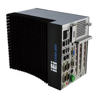
Fanless Embedded System wtih Intel Atom D525 Dual Core CPU, VGA, Two Gigabit Ethernet, Four USB, RS-232/422/485, RoHS Compliant
Brand:
IEI Technology
| Category:
Desktop
| Size: 4.97 MB
Table of Contents
Table of Contents
6
1 Introduction
12
Figure 1-1: TANK-800
13
Table 1-1: TANK-800 Model Variations
14
Table 1-2: Technical Specifications
16
Connector Panel
17
Figure 1-2: TANK-800 Peripheral Connectors
17
Figure 1-3: TANK-800 LED Indicators
18
Led Indicators
18
Backplane Options
19
Technical Specifications
15
Overview
13
Features
14
Model Variations
14
Figure 1-5: TANK-800-D525/1GB/1P2E-R10 Backplane (HPE-3S7)
19
Figure 1-4: TANK-800-D525/1GB/2P1E-R10 Backplane (HPE-3S6)
19
Table 1-3: Supported Signals
19
Table 1-4: Rated Voltage and Current
20
Dimensions
21
Figure 1-6: Physical Dimensions (Millimeters)
21
2 Unpacking
22
Anti-Static Precautions
23
Unpacking Precautions
23
Unpacking Checklist
24
3 Installation
27
Cf Card Installation
28
Installation Precautions
28
Figure 3-1: CF Card Slot
29
Figure 3-3: CF Card Installation
30
Figure 3-8: Remove the HDD Bracket from the Cover
33
Figure 3-10: Remove the Temporary Retaining Bracket
34
Figure 3-9: Remove the Fan Bracket from the Cover
34
Figure 3-11: Secure the System Fan to the Fan Bracket
35
Figure 3-12: Reinstall the Fan Bracket
35
Figure 3-13: Pluggable DC-In Terminal Block Installation
36
Figure 3-14: Mounting Bracket Retention Screws
37
Mounting the System with Mounting Brackets
37
External Peripheral Interface Connectors
38
ACC Mode Selection
39
AT/ATX Power Mode Selection
39
Figure 3-15: ACC Mode Switch
39
Figure 3-16: AT/ATX Power Mode Switch
39
Audio Connector
40
Compactflash® Type II
40
Digital Input/Output Connector
40
Figure 3-17: Audio Connector
40
Figure 3-18: DIO Connector Pinout Location
41
LAN Connectors
41
Table 3-1: DIO Connector Pinouts
41
Figure 3-19: LAN Connection
42
Figure 3-20: RJ-45 Ethernet Connector
42
Table 3-2: LAN Pinouts
42
Figure 3-21: 3-Pin Terminal Block Pinout Location
43
Power Input, 3-Pin Terminal Block
43
Power Input, 4-Pin DIN Connector
43
Table 3-3: RJ-45 Ethernet Connector Leds
43
Figure 3-22: Power Input Connector
44
RS-422/485 Serial Ports
44
Table 3-4: Power Input Pinouts
44
Figure 3-23: RJ-45 RS-422/485 Serial Device Connection
45
Figure 3-24: RJ-45 RS-422/485 Serial Port Pinout Location
45
Table 3-5: RJ-45 RS-422/485 Serial Port Pinouts
45
Figure 3-25: DB-9 Connector Pinout Location
46
Serial Port Connectors
46
Table 3-6: DB-9 Connector Pinouts
46
Figure 3-26: Serial Device Connector
47
Figure 3-27: Serial Port Pinout Location
47
Table 3-7: Serial Port Pinouts
47
Figure 3-28: USB Device Connection
48
USB Connectors
48
Table 3-8: USB Port Pinouts
49
VGA Connector
49
Figure 3-29: VGA Connector
50
Figure 3-30: VGA Connector
50
Table 3-9: VGA Connector Pinouts
50
Figure 3-31: Power Button
51
Powering On/Off the System
51
Redundant Power
51
Acc on
52
Figure 3-32: Power Connectors
52
Boot-Up
53
Figure 3-33: ACC On: at Mode
53
Figure 3-34: ACC On: ATX Mode
53
Switch to Backup Power
53
Figure 3-35: ACC On: Switch between PWR1 and PWR2
54
Figure 3-36: ACC On: Shutdown
54
Shutdown
54
Acc off
55
Boot-Up
55
Figure 3-37: ACC Off: at Mode
55
Figure 3-38: ACC Off: ATX Mode
55
Switch to Backup Power
55
Figure 3-39: ACC Off: Switch between PWR1 and PWR2
56
Figure 3-40: ACC Off: Shutdown
56
Shutdown
56
Figure 3-2: CF Card Slot Cover
29
Pluggable DC-In Terminal Block Installation
36
Hard Disk Drive (Hdd) Installation
30
Figure 3-4: Unscrew the Cover
31
Figure 3-5: Remove the Cover from TANK-800
31
Figure 3-6: HDD Installation
32
Figure 3-7: HDD Retention Screws
32
System Fan Installation
33
4 Bios
57
Introduction
58
Starting Setup
58
Using Setup
58
Getting Help
59
Unable to Reboot after Configuration Changes
59
BIOS Menu Bar
59
Table 4-1: BIOS Navigation Keys
59
Main
60
Advanced
61
ACPI Settings
62
CPU Configuration
63
IDE Configuration
64
USB Configuration
66
Super IO Configuration
67
Serial Port N Configuration
68
H/W Monitor
74
Serial Port Console Redirection
75
Iei Feature
77
Chipset
78
Host Bridge Configuration
79
South Bridge Configuration
79
Intel IGD SWSCI Opregion
81
Boot
82
Security
83
Exit
85
A Regulatory Compliance
87
B Safety Precautions
92
Safety Precautions
93
General Safety Precautions
93
Anti-Static Precautions
94
Product Disposal
95
Maintenance and Cleaning Precautions
95
Maintenance and Cleaning
95
Cleaning Tools
96
C Digital I/O Interface
97
Introduction
98
Assembly Language Sample 1
99
Assembly Language Sample 2
99
D Hazardous Materials Disclosure
100
Hazardous Materials Disclosure Table for IPB Products Certified as Rohs Compliant under 2002/95/EC Without Mercury
101
Advertisement
Related Products
IEI Technology TANK-860-HM86 Series
IEI Technology TANK-860-HM86i-i5/4G/2A-R10
iEi TANK-860-HM86i-C/4G/6A-R10
IEI Technology TANK-860-HM86i-i5/4G/4A-R10
IEI Technology TANK-860-HM86i-i5/4G/6A-R10
IEI Technology TANK-860-HM86i-C/4G/2A-R10
IEI Technology TANK-820-H61 Series
IEI Technology TANK-820-H61-i5/2G/2P1E-R10
IEI TANK-820-H61-i5/2G/1P2E-R10
IEI TANK-820-H61-i3/2G/1P2E-R10
IEI Technology Categories
Motherboard
Touch Panel
Computer Hardware
Single board computers
Desktop
More IEI Technology Manuals
Login
Sign In
OR
Sign in with Facebook
Sign in with Google
Upload manual
Upload from disk
Upload from URL